HIOS VZOP-STC User manual

Power Supply with Screw Counter
VZOP-STC
Instruction Manual
(March 2009)
For VB-OPC screwdriver For VZ-OPC screwdirver
Hios Inc.
111-6,Akiyama, Matsudo, Chiba Pref. Japan, 270-2223
TEL: +86(Japan)47-392-2001
FAX: +86(Japan)47-392-7773
09A Operation Manual No.ET-A009

2
Outline of the VZOP-STC
When performing work that requires screws to be tightened with an electronic screwdriver,
the operator must check that the correct number of screws has been used for a particular
piece of work in order to prevent the work piece leaving with screws that have not been
tightened.
The VZOP-STC screw counter makes use of the OPoutput signals (normal rotation signal,
torque up signal, reverse rotation signal) from the screwdriver to allow the operator to check
if any screws require tightening.
The VZOP-STC features a power source (DC 24 V / 0.3A) to power external equipment as
well as an input/output signal to control them.As such, the unit can be connected directlyto
an interlocking solenoid valve to prevent careless mistakes made by the operator.
(When using a jig that prevents removal of the work piece before the all screws are fully
tightened)
The operator can also select a function that reverses (increases) the count if a reverse
signal is input to the screwdriver to loosen the screws (selected with mode SW3).
Another option allows the reverse count up time to be set when screws are biting (normally
not counted). This time can be set between 0.2 and 1.0 seconds. A switch has been
installed on the internal circuit board to allow the normal operator to change the settings.
The factory default setting is level 2 (0.2 seconds) (level 1 cannot be used).
Note: Changing the settings can be dangerous. Only change settings after removing the
power plug.
The SET signal is set when power is supplied to the unit, meaning that it is possible to
provide effective management that is not reliant on the operator during cell production
when one operator is required to uses several screwdrivers. The ER BZ output signal
warns of the presence of incomplete work when the work check switch is OFF. The unit
may be reset or the signal will be output until the work is completed. This signal can be
used by attaching a warning buzzer to warn the operator.

3
VZOP-STC Specifications
Input voltage :AC 100 V ±5% 50/60 Hz
Power capacity : 100W
Fuse capacity : 6A/ 250 V (with one spare fuse)
Dimensions : 160 (W) x 175 (D) x 84 (H)
Weight : 1.5 Kg
AC cord length : 1.8 m (with ground)
Supplied accessories : 8 terminals, 1 slotted screwdriver
Compatible drivers: VB-OPC specification driver
VB-1510-OPC
VB-1820-OPC
VB-3012-OPC including PS type
VB-4504PS-OPC
VZ-OPC specification driver
VZ-1510-OPC
VZ-1820-OPC
VZ-3012-OPC
Including PS type
VZ-4506-OPC

4
Please read through the electronic screwdriver instruction manual carefully before
use and use only as per instructions.
- Installation area
1. Always install a ground leakage breaker and safety breaker to commercial power
supplies.
2. Install the unitin an area that is not subjected to dust, dirt or metal fragments.
3. Install the unitin an area that is not subjected to water or oil.
4. Do notplace heavy items on top of the unit or stack units on top of one another.
5. Select a safe installation area that is free from vibration.
6. If the unit is to be installed in an elevated location, ensure that it is fixed firmly so that
there is no danger of the unit falling.
7. Do not install the unit near other high-voltage equipment or electronically noisy
environments.
8. Do not use input and output cables that are longer than required or knot them. Doing so
may result in incorrect reading.
- Precautions for use
1. Ensure that the unit is grounded and that the specified rated power and voltage are used.
2. Ensure that loads connected to the output terminals on the rear panel terminal block do
not exceed the rated load.
3. If external equipment connected to the +DC 24 V output terminal or input/output
terminals on the rear panel terminal block are affected by the electromagnetic induction
of relays and solenoid valves coils, noise prevention in the form of reverse voltage
absorbing diodes should be used. Equipment may operate incorrectly or malfunction if
noise prevention is not used.
4. Do not connect the +24 V DC terminals on the rear panel terminal block to any output
terminal or GND terminal.
5. If the unit’s functions are used to power external equipment with an external power
source, a common GND terminal should be used. Equipment may operate incorrectly or
malfunction if a common GND is not used.
6. Do not provide additional voltage to the input or output terminals. Additional voltage will
result in a malfunction.
7. Use the unit in temperatures of 5°C to 40°C and 80% or less humidity (with no
condensation).
8.Always hold the plug when connecting or removing the power cord or driver cord.
9. Do not pull the cords, drag them across oil or sharpedges, or place heavy objects on top
of them. Doing so may result in severed wires or malfunctions.
10. If a malfunction occurs and the unit overheats or the fuse blows, stop using the unit
immediately and turn off the main power switch, remove the power cord from the power
outlet and bring the unit to our service department.

5
11. When tightening screws on plastic work pieces that may have a lot of static electricity
buildup, remove electricity before starting work. If electricity is not removed, static
electricity may flow from the end of bit, resulting in incorrect operation.
12. Do not drop or subject the unit to strong shocks.
13. Do not use drivers other than those manufactured by Hios. Doing so may result in a
malfunction.
14. Turn the main power switch OFF if the unit is not used for a prolonged period of time,
and remove the power plug.
15. Never dismantle or modify the unit by yourself. Doing so may result in a malfunction
and void the warranty or make it impossible to be repaired.

6
Front Panel
Main SW : Turns the power to the counter on and off. The LED display
will
turn green when the power is on.
Reset Button : Click once during or after setting the screw count. The set
value will be displayed. This has the same function as the reset
signal on the rear panel terminal block.
Operating Display LED : Lights up when solenoid valves have been set by the set
signal on the rear panel terminal block.
Display : Displays the set number of screws. The number counts down
as screws are tightened and show how many screws are
remaining.
Count Set SW : This switch sets the number of screws to be tightened, and
can be set from 1 to 99 screws. Set units of 10 and 1
individually. Click the reset button once during or after setting
the number of screws to confirm the screw count. Rotate the
supplied slotted screwdriver to change settings.
CountTimer : This timer prevents incorrect screw counts when tightening a
screw that hasalready been tightened a second time.
Use the digital switch to set the time in 1/100 increments to be
ignored for the count when using the driver to tighten screws
that have alreadybeen tightened (0.01 to 1.00 seconds).
Operating Display LED
Work Set Timer
Display
Count Timer
Reset Button
Work Reset
Timer
Count Set switch
Main
switch

7
Work SetTimer : Adjusts for the time between the input set signal on the rear
panel terminal block and start of operationof the solenoid valve
(0.1 to 3 seconds).
Work ResetTimer :Adjusts for the time between the completion of work and when
the solenoid valve turns off. A buzzer sounds at the same time
(0.1 to 3 seconds).
* Caution!! Do not apply excessive force when setting volume knobs or switches. Doing so
may result in a malfunction.
8
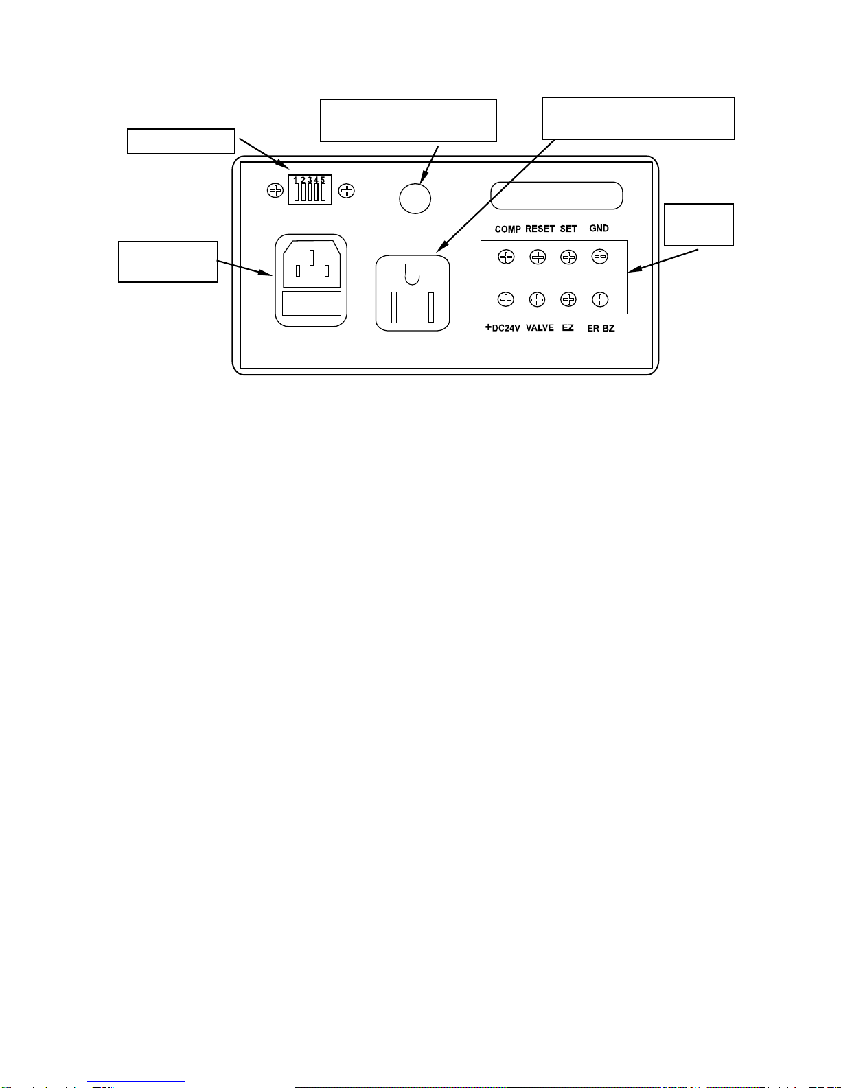
Rear Panel
GND : GND for input and output.
SET : The Operating Display LED on the front panel will light up and
the VALVE signal turned ON when the signal received from the
external switch when the work is set is shorted to ground and
the time set on the set timer elapses.
RESET : The unit is reset when work is stopped as a result of defective
work and GND is shorted.
COMP : Output will continue for 0.1 seconds after the screws have
been tightened and the buzzer has finished sounding.
(Open collector output DC 30 V / 0.1A)
ER BZ : Output will continue until work is complete or the unit is reset
when the work piece is removed during operations (before
work is complete). A warning can be generated by connecting
an error buzzer.
BZ : A signal generated in time with the buzzer when the final
screw has been tightened (open collector output DC 30 V /
0.1A).
VALVE : Used after the set input signal has been received and the
solenoid valve (DC 24 V) has started operating. Connect the +
terminal of the solenoid valve to the +DC 24 V terminal block
and –terminal to the VALVE terminal on the rear panel. If other
voltages are used, use an external power source with a
For VB-opc driver or VZ-opc
driver 100V output socket
Connector for OPC drivers
Signal cord
AC inlet with
fuse holder
Terminal
Block
Mode Switch

9
common GND terminal (open collector outputDC 30 V / 0.1A).
+DC 24 V : Power source for powering external equipment. The power
capacity is DC 24 V / 0.3A.
Mode Switches
1 : The work complete notification buzzer (built in) no longer sounds if switched
OFF.
2 : The panel display turns off if switched OFF.
3 : The reverse rotation countup operation turns off if switched OFF.
4 : When switched OFF, the unit will only work once the set input signal is received.
5 : Unused.
10
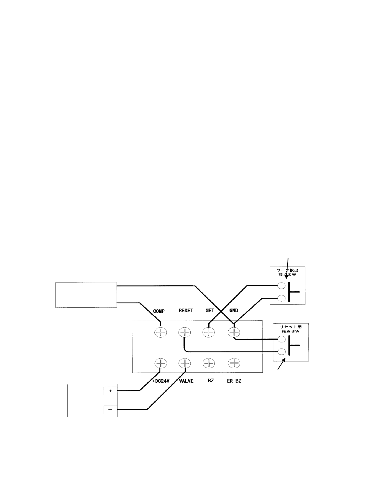
Basic Operations
Example 1: When a solenoid valve is used to hold work placed by the operator on the
bench and the work is released by the valve and moves to the next production
process once all screws have been tightened. (The work piece is not released
until all screws have been tightened).
1. Connect the external switch to SET and GND on the rear panel terminal block (no
polarity if an external switch is used and common GND if an open collector is used before
connecting the output signal to SET).
2. Connect the + terminal of the solenoid vale to +DC 24 V, and –terminal to VALVE on the
rear panel terminal block.
3. Connect the switch (contact point) for releasing the work if operations are stopped to
RESET and GND.
4. Connect the driver and adjust CN-T to a position that does not count down even if the
driveris used to further tighten screws that have already been tightened.
5. Adjust WS-T to the time taken for the solenoid valve to operate after the work piece
arrives.
6. AdjustWR-T to the time taken to turn the solenoid valve OFF after all screws have been
tightened.
7. Connect a commercially available counter to the COMP signal and GND on the rear
panel terminal block to manage the total number of completed work pieces.
Solenoid
Valve
Work Rest
Switch
Work Detection
Switch
Total Counter

11
Basic Operations
Example 2: When one operator is using two drivers and two varieties of screws and the
work piece is not secured. When you only want to use one driver.
(2 VZOP-STC units are being used and are namedA& B respectively)
1. Connect the external switch to SET and GND on the rear panel terminal block ((no
polarity if an external switch is used and common GND if an open collector is used
before connecting the output signal to SET).
2. Connect bothAand B GND (common GND).
3. ConnectACOMP and B SET.
4. Set Amode SW1 to OFF (so that the buzzer forA does not sound).
5. Connect a total counter to B COMP and GND.
Total Counter
Work Rest
Switch
Work Detection
Switch
Total Counter
Table of contents
Other HIOS Power Tools manuals


