ZEEWEII DSO3D12 User manual

DSO3D12
User’s Manual
Designed by ZEEWEII
DIGITAL OSCILLOSCOPE

2
① Green is the running state; Flashing cyan for waiting to trigger; Red is stopped.
② Channel priority: Yellow 1 indicates that CH1 has high priority, and the CH1
waveform can be moved up or down.
③ Yellow: Turn on the signal generator output; Gray: Turns off the output.
④ Shows the position of the current time base window in memory.
⑤ Auto indicates that the trigger mode is automatic. Normal indicates that the trigger
mode is normal.
⑥ Trigger edge: Rising edge trigger or falling edge trigger.
⑦ Battery level indication.
⑧ Trigger level position.
⑨ X1/X10 indicates probe attenuation, which should be set to match the probe. The
goal is to tell the oscilloscope what attenuated probe you used.
⑩ DC/AC coupling.
⑾ Vertical sensitivity: Indicates the voltage of a grid.
⑿ Timebase: The time of a grid.
⒀ Zero arrow: The baseline position, where the vertical voltage is zero.
Note: (CH2 icon is gray to indicate that it is off, if you do not need to test two signals
at the same time, please close CH2 to obtain higher sampling rate and reduce power
consumption).

3
Buttons Function
1. Default function (function on button)
OK
Auto
1. When the menu opens, as the OK button.
2. as an "Auto" button
Stop Run / Stop
Single Single trigger
AC/DC Switch DC/AC coupling(CH1)
CH1/CH2 Change the CH1/CH2 priority
Menu Open/close the menu
Shift
⬆
When this button is pressed, the functions on the case will be
performed.
x1x10 Probe attenuation, which tells the oscilloscope what probe range you
are using. (CH1)
Gen Turn on/off the signal generator interface
Save Save a screenshot of the waveform
50% Quick centering (CH1)
DMM Turn the multimeter on/off. (Press Shift+DMM to full screen)
Select Multimeter function selection
mV/V Adjust vertical sensitivity (voltage of one grid)
s/ns Adjust the time base (the time of one grid)
2.Second function(Shift + other buttons)
Auto2 Enter real-time auto (CH1 only). Press any key to exit.
Zoom Turn on/off zoom mode.
Ref Reference waveform, the current waveform is locked to the
screen as a reference.
AC/DC Switch DC/AC Coupling (CH2).
CH2 Open/close CH2.
TgMode Change trigger mode: Auto / Normal.
x1x10 Probe attenuation, which tells the oscilloscope what probe range
you are using. (CH2)
TgEdge Change the trigger edge: rising edge/falling edge.
View View waveform screenshots

4
50% Quick centering (CH2)
Full The multimeter is displayed in full screen
Tg1/2 Switch trigger source: Ch1 / CH2
Note:
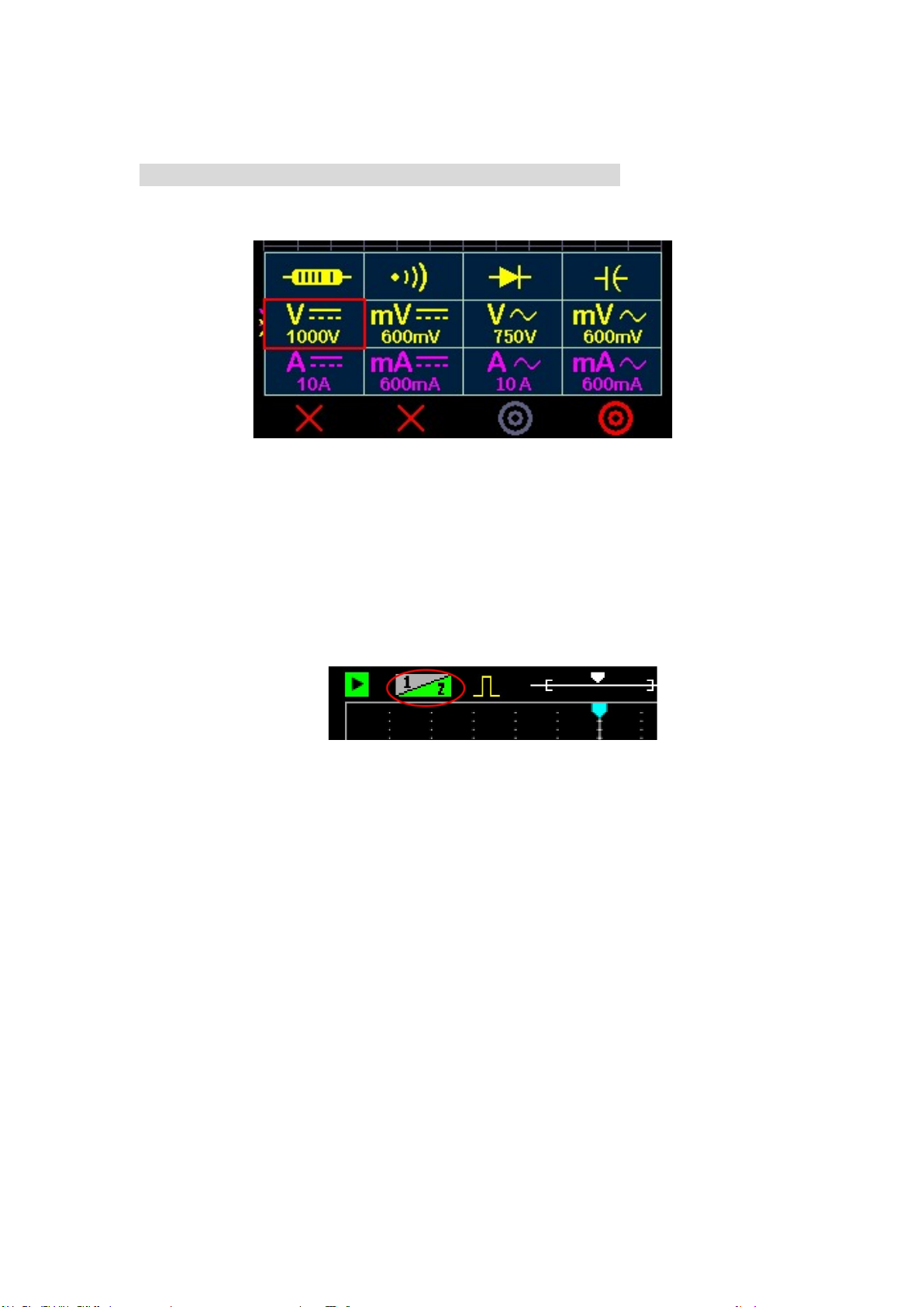
CH1 cannot be turned off, CH2 can be turned on or off. When two channels are
not required, CH2 should be turned off for higher sample rates and reduced power
consumption.
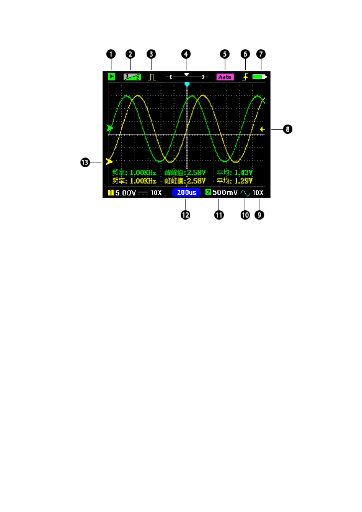
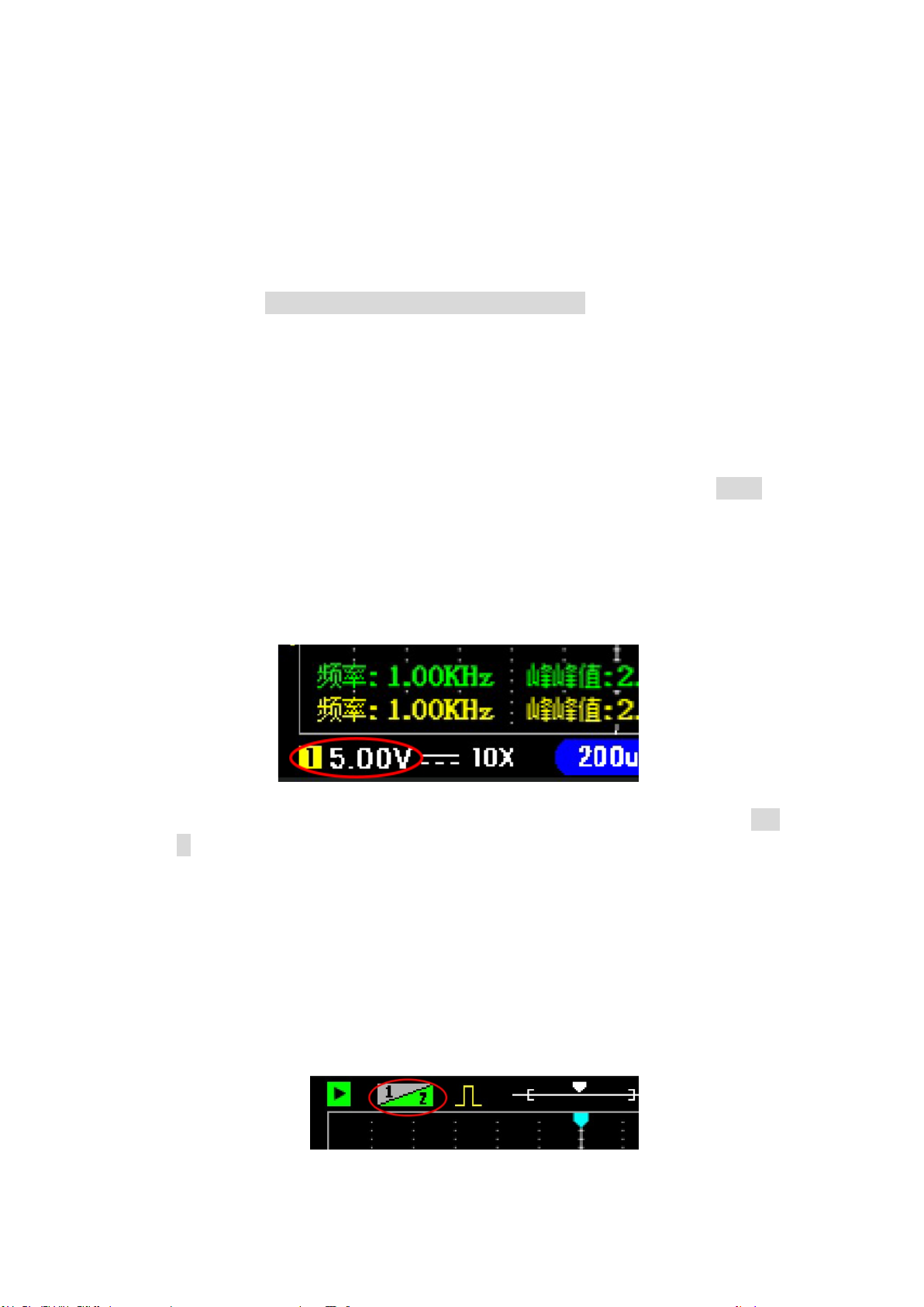
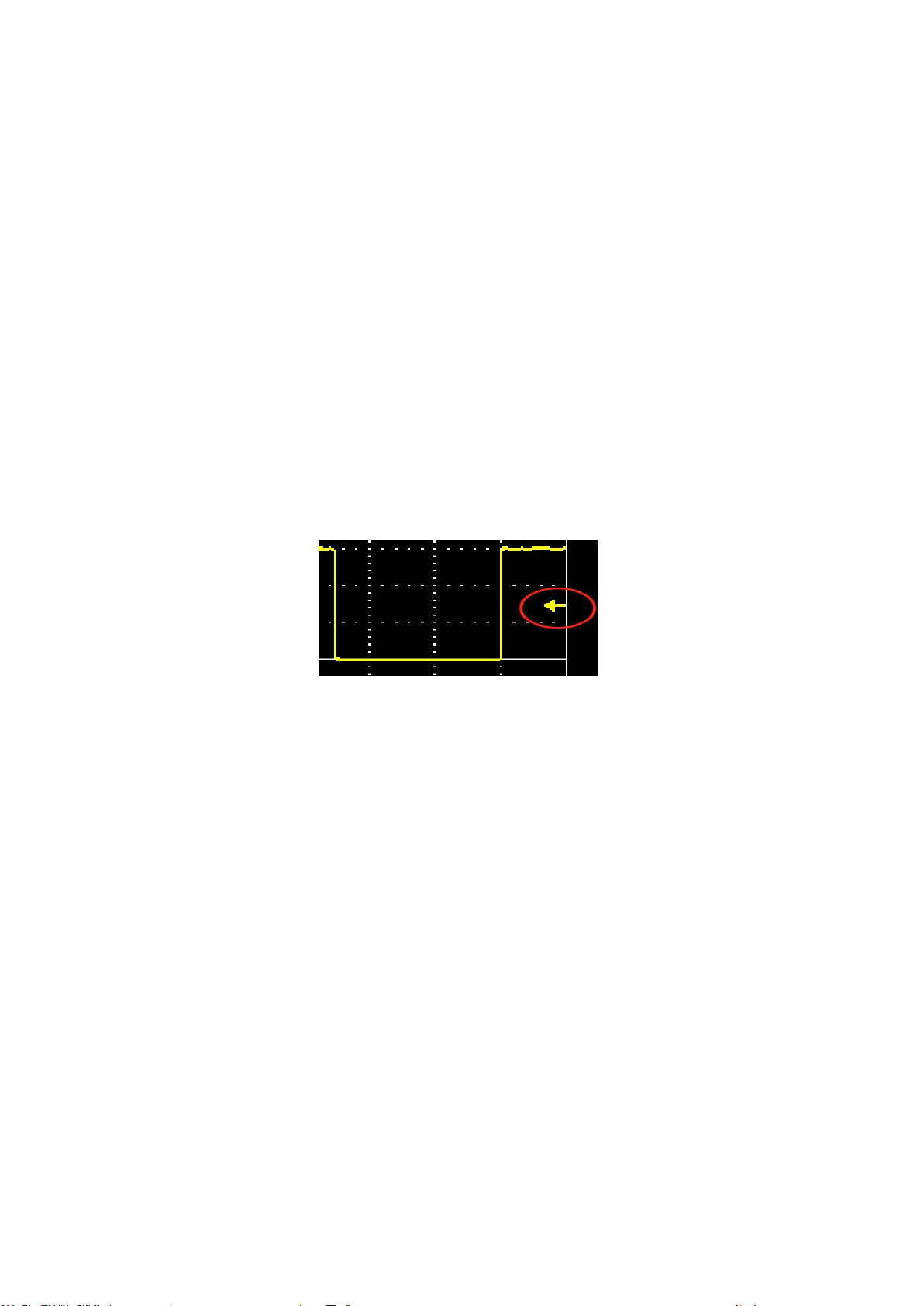
About trigger levels:
The small arrow on the right side of the screen is yellow to indicate that the
trigger source is CH1, and green indicates that the trigger source is CH2.
The default trigger level is automatic adjustment, if you need to adjust it manually,
you need to set the trigger level to "manual" in the menu, you can adjust the trigger
level position arbitrarily (click the Shift key to move the trigger level up and down).
Auto2: RtAuto appears in the upper right corner of the screen, indicating real-time
automatic adjustment. When the probe is connected, the oscilloscope automatically
adjusts the range in real time. Press any key to exit.
Shift+V(ch1): Turn on/off the voice assistant.
1 Safety Precautions
High voltage. The x10 range of the probe measures up to 220V. An x100
probe is required for overreach.
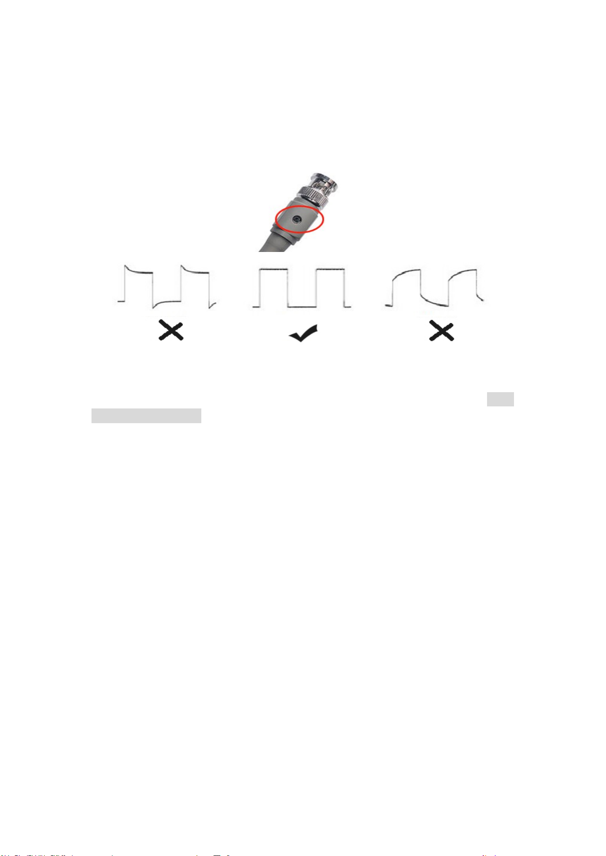
Probe attenuation. Before measuring voltages greater than 40V, switch the
probe to the X10 position.
Charge. The charging voltage is 5V, use a computer or mobile phone
charger.
When measuring high-voltage or non-isolated circuits, it cannot be used
while charging (powered by a built-in battery).
Do not use a multimeter while charging.
Never insert the red probe into the current hole to measure the voltage, it
will blow the fuse or even damage the machine. After measuring the current,
remember to change the red probe to the voltage hole, remember!!
When the multimeter measurement current is greater than 6A, the
duration should not exceed 10 seconds to avoid line damage caused by heating.
When measuring high voltages, do not use the oscilloscope and multimeter
at the same time.

5
2 Quick start instructions
2.1 Power
Press and hold the power button on/off.
When the battery is dead, use the USB cable to connect to the 5V adapter for
charging, and the charging current is about 700mA. It is best to use a computer or
mobile phone for charging. The LED lights up red when charging, and turns green
when fully charged.
2.2 Auto
After the probe is connected to the signal, press the [Auto] button, and the
oscilloscope will automatically detect the signal and adjust the range. If there is no
waveform, the probe may not be connected correctly, or there may be no signal at the
connection (you can use a multimeter to determine if there is a voltage).
2.3 Sensitivity and time base
Manual adjustment: “mV”/ “V” buttons scale the waveform vertically. The “s”/
“ns” button scales the waveform horizontally.
The vertical sensitivity indicates the voltage of a grid in the vertical direction,
and it is adjusted by the mV and V buttons to adapt to different voltages.
The time base represents the time of a grid horizontally. It is adjusted by the S
and NS buttons to accommodate different frequencies.
2.4 Test built-in signal generator
1. Connect the probe to the generator output pin. 2. Press the [Gen] key to open
the generator interface, and then press the [Stop] key to change the generator to the
[ON] state. Press the [ns] key to switch waveforms. Press the [Single] key to reset to
1.00Khz. 3. Press [OK] to exit the interface.
4. After pressing the [Auto] key, you can see the waveform of the generator.
2.5 Use of Multimeters
Check the red pen first in the voltage hole. Press the [Select] key to open the

6
multimeter function table, select the function and press the [OK] key.
If you want to measure the current, insert the red pen into the current hole, and
pay attention to the "series" of the meter pen and the power line.
When charging: Multimeter is not supported, and the oscilloscope cannot
measure high voltage or non-isolated circuits.
2.6 Use dual channels
Press the [Shift] key, and then press the [CH1/CH2] key to open/close channel 2.
The default up and down keys move the channel 1 waveform, if you need to move the
channel 2 waveform, you can press [CH1/CH2] to set the high priority of channel 2
(pay attention to the change of the 1/2 icon in the upper left corner).
When not using dual channel measurements, Channel 2 should be turned off for
higher sample rates and reduced power consumption.
3 Probes
3.1 Probe calibration
The probes delivered with this machine have been compensated. If you use
another new probe before the first use, it must be calibrated before it can be used
normally, otherwise the measurement will be inaccurate (only for the 10X/100X). The
calibration method is as follows:
1. Switch the probe to X10.
2. Connect the probe to a 1KHz square wave with an amplitude of about 2V-3V. You
can use the built-in generator.
3. Adjust the horizontal and vertical scales of the oscilloscope so that the waveform

7
is displayed stably at a suitable position on the screen.
4. Use a screwdriver to rotate the adjustable capacitor on the probe until you get the
waveform in the middle of the figure below. The left and right waveforms below
are references for incorrect calibration.
3.2 Probe bandwidth
Because the 1X probe has a large input capacitance, the bandwidth of the 1X is
usually within 5MHz; while the bandwidth of the 10X is the standard bandwidth of
the probe.
3.3 Probe withstand voltage
The maximum withstand voltage of the probe is generally marked on the probe,
which is usually 600Vpk-pk.
3.4 Use tips
3.4.1 Large input capacitance
Because the probe 1X has a large input capacitance (usually more than 100 pf), it
is not suitable for measuring some capacitively sensitive circuits. For example, when
measuring a passive crystal of MCU, the large capacitor may cause the crystal to fail
to vibrate. As for the output of a high-speed op amp, a capacitive load may cause the
op amp to overshoot or oscillate. For circuits with large capacitances that are not
suitable for measurement, please use 10X. The input capacitance of the 10X is usually
several pf.
3.4.2 Measuring high voltage
The oscilloscope's measurement voltage range is -40V ~ + 40V (80Vpp). Please
use the 10X probe to attenuate the signal by 10 times beyond this range. The
measurable voltage range of 10X range is 600V(DC+AC). Please note that you must

8
first switch the probe to the 10X position before connecting the high voltage signal,
otherwise the high voltage may break down the internal circuit of the oscilloscope.
3.4.3 High bandwidth
Because the 1X probe has a large input capacitance, the bandwidth of the probe
1X is usually within 5MHz, so please use the 10X position when the measured signal
bandwidth is greater than 5M.
Summary: 10X is usually used in most applications.
4 Vertical system
4.1 Vertical sensitivity
Oscilloscope vertical sensitivity refers to the voltage represented by a grid in
the vertical direction of the screen. There are 8 divisions in the vertical direction of
the oscilloscope. You can estimate the amplitude of the signal by observing how many
divisions the waveform occupies on the screen. For example, if the vertical sensitivity
is 1v/div, and the signal occupies 3 grids on the screen, you can know that the
amplitude of the signal is 3V.
The scope's vertical sensitivity range is 10mV / div ~ 10V / div (1X probe). In
the oscilloscope button panel, the keys for adjusting the vertical sensitivity are 'mV'
and 'V' button. Pressing the 'mV' button decreases the vertical sensitivity, which is
used to measure signals with smaller voltage amplitude. Press the 'V' button to
increase the vertical sensitivity for measuring signals with larger voltage amplitudes.
4.2 Vertical position
How to move the waveform up and down: Press the up and down buttons
directly to move the waveform up and down. The number in the upper left corner is
yellow 1 for movable channel 1, click the "CH1/CH2" key to switch to green 2
movable channel 2.

9
5 Horizontal system
5.1 Time base
The time base refers to the time represented by each grid in the horizontal
direction on the oscilloscope screen. There are 12 grids in the horizontal direction of
the oscilloscope. The sampling time that can be observed on the screen = " time base"
* 12.The user can estimate the signal period by observing how many grids a
waveform period occupies. For example, the current time base is 500us, and one cycle
of the signal occupies 2 grids,so the signal period is 1ms (1KHz).
The oscilloscope time base range is 5ns ~ 10s. The buttons for adjusting the time
base in the oscilloscope button panel are 'ns' and 's' button.,When observing
high-frequency signals, you should press the 'ns' button to decrease the time base.
When observing low-frequency signals, you should press the 's' button Increase the
base.The time base in the figure is 200us/div.
What you need to know is that the sampling process of the oscilloscope is:
"Sampling">>"Processing" >> "Display"
When adjusted to a large time base, the screen waveform refresh will be slow
due to the longer time taken by the oscilloscope to sample the waveform.
5.2 Horizontally moving waveform
In the stop mode, the user can move the waveform left and right.
6 Trigger system
About trigger
The oscilloscope will capture a frame of waveform only after the waveform

10
meets the pre-set conditions. This action of capturing the waveform according to the
conditions is the trigger.
What does trigger do?
1. Trigger can stabilize the waveform on the screen.
2. Capture the segment of the waveform you want to observe.
The trigger supported by the oscilloscope is edge trigger, including rising edge
trigger and falling edge trigger.
6.1 Trigger level
In the edge trigger mode, the trigger condition appears only when the waveform
crosses up or down the trigger level.
The trigger level is automatically adjusted by default. Here's how to adjust
manually:
a. In Menu-> Trigger, change "Trigger Level" to "Manual".
b. Press the “Shift” key, and then click the up and down keys to move the trigger
level.
The arrow circled above is the trigger level position, and when the edge of the
square wave in the above figure passes upwards through the position of this arrow, a
trigger is formed (the waveform only forms a trigger when it crosses the trigger level
up or down).
6.2 Trigger Sources
The small arrow on the right, yellow indicates that the trigger source is CH1, and
other color indicates that the trigger source is CH2. Which channel is used as a
trigger can stabilize the waveform of which channel, and two channels cannot be
triggered at the same time.
6.3 Trigger Mode
Trigger mode: automatic trigger, normal trigger, single trigger. Automatic
triggering is more commonly used. The normal trigger will not refresh the screen
when there is no waveform, suitable for measuring some pulse signals that come
occasionally, etc., and refresh the waveform once in a pulse. The single-trigger
procedure is described in 7.2 below.

11
7 Operation Guide
7.1 50%
The role of 50% is to quickly return to the center, including zero point offset,
trigger position, trigger level will quickly return to the middle position with one
button, operation method: directly click "50%".
7.2 Single trigger
Suitable for sporadic single pulse capture.
A single trigger is when the single button is pressed, and the oscilloscope
samples a frame of waveform and then stops. That is, only one frame of
waveform is taken per press. It is important to note that this sampling must be
triggered, if it is not triggered, the upper left corner of the oscilloscope flashes
"||", and the sampling is not completed until there is a waveform trigger. To
cancel a single trigger, click "Stop" to stop.
Procedure:
1. Connect the signal first.
2. mV/V set the voltage sensitivity, s/ns set the time base.
3. Set the trigger level to "manual" and adjust the trigger level (when you
can't do it, see the previous section).
4. Press the Single key once.
5. The oscilloscope waits for the signal to arrive, and once a waveform
crosses the trigger level, the oscilloscope completes a sample and then stops.
7.3 Screenshot
Click the "Save" button to capture the current screen.
7.4 View images
After pressing the Shift key, than press the Save key to enter the Image View
window. In this window, the user can delete or browse historical screenshots.
Click the “x1x10” button to delete the current screenshots.
Click the "ok" button to zoom in on the waveform. After zooming in, click "ok"
to return to the homepage.
Click the " Save " button to return to the oscilloscope window.

7.5
Signal generator
Click the " Gen "
button
amplitude is 2.5V, the maximum frequency of the sine wave is
waves are 1M.
Click the " Stop"
button to
Click the "Single
" button to
Click the "s" and "
ns
wave, triangle wave, etc.
Click "Ok" or "Gen"
Square wave
can adjust the duty cycle, other waveforms do not work.
Note:
When the set frequency is greater than 1MHz, the square wave signal may
show small horizontal jitter
7.6
Single/dual channel
Shift” +"CH1CH2
" button to turn on/off
cannot be turned off. When you do not need to use two channels at the same time,
please turn off CH2
to obtain a higher sampling rate and reduce power consumption.
When using dual channel mode, click the "CH1CH2" button to
CH1 and CH2.
If CH1 has a high priority, the waveform of CH1 is moved by the up
and down buttons.
7.7 Cursor
Press the “Shift” +
"s" key to turn the horizontal cursor on/off.
Press the “Shift” +"n
s"key to turn the vertical cursor on/off
Press the left and right arrow keys directly to move the horizontal cursor 1. After
pressing the Shift key, press the horizontal arrow key again to move the horizontal
cursor 2. The same goes for vertical cursors.
For vertical cursors, Y1: The voltage a
the dashed line below. dY=Y1
12
Signal generator
button
to call up the window
of the signal generator,
amplitude is 2.5V, the maximum frequency of the sine wave is
5
M, and the other
button to
turn on/off the signal generator output.
" button to
reset the number to: 1.00Khz, 50%
ns
" keys to switch the output waveform
: sine wave, square
to confirm and exit.
can adjust the duty cycle, other waveforms do not work.
When the set frequency is greater than 1MHz, the square wave signal may
show small horizontal jitter
.
Single/dual channel
" button to turn on/off
CH2. CH
1 can only be turned on and
cannot be turned off. When you do not need to use two channels at the same time,
to obtain a higher sampling rate and reduce power consumption.
When using dual channel mode, click the "CH1CH2" button to
switch the priority of
If CH1 has a high priority, the waveform of CH1 is moved by the up
"s" key to turn the horizontal cursor on/off.
s"key to turn the vertical cursor on/off
.
Press the left and right arrow keys directly to move the horizontal cursor 1. After
pressing the Shift key, press the horizontal arrow key again to move the horizontal
cursor 2. The same goes for vertical cursors.
For vertical cursors, Y1: The voltage a
t the dashed line above. Y2: The voltage at
the dashed line below. dY=Y1
-
Y2, which is the voltage difference between the two
of the signal generator,
The signal
M, and the other
: sine wave, square
can adjust the duty cycle, other waveforms do not work.
When the set frequency is greater than 1MHz, the square wave signal may
1 can only be turned on and
cannot be turned off. When you do not need to use two channels at the same time,
to obtain a higher sampling rate and reduce power consumption.
switch the priority of
If CH1 has a high priority, the waveform of CH1 is moved by the up
Press the left and right arrow keys directly to move the horizontal cursor 1. After
pressing the Shift key, press the horizontal arrow key again to move the horizontal
t the dashed line above. Y2: The voltage at
Y2, which is the voltage difference between the two

13
dashed lines. The vertical (voltage) cursor can only measure one channel, and
whichever channel has the highest priority, measure the voltage of which channel.
8 Menu introduction
8.1 Channel
The channel menu includes two options, "Coupling" and "Probe".
The coupling can be set "DC coupling" and "AC coupling". DC coupling passes
the signal directly. AC coupling is equivalent to series connection with the capacitor.
Probes are available in " 1X" / "10X"/ "100X", this option corresponds to the
oscilloscope probe. When the probe is switched to the 10X position, this option
should be selected as " 10X". The same goes for the 1X.
8.2 Measurement
There are 14 measurement options available, as shown below:
Frequency, Peak-to-Peak, Duty cycle, Amplitude, RMS, Average, Period, +Pulse
width, -Pulse width, Max, Min,Top, Base, -Duty cycle.
The difference between peak-to-peak and amplitude(AMP) is shown in the
figure above.
8.3 Trigger
There are four options in the trigger menu: “Trigger Mode” ,“Trigger Type” ,
“Trigger level”and “Trigger source”.
Trigger Mode can be selected from "Auto" and "Normal".
For “Auto” mode, if a waveform trigger is detected, the waveform will be used
for triggering. At this time, the waveform can be displayed stably. If the oscilloscope
cannot detect the trigger condition, it will automatically force the trigger to display the
waveform, but because there is no suitable trigger condition, the waveform will not be
displayed steadily.

14
For “Normal” mode, The oscilloscope will not refresh the display until there is a
waveform trigger. Therefore, in this mode, the screen waveform may not refresh or
there is no waveform. It is suitable for measuring discontinuous waveforms and
requires users to adjust the trigger level in advance.
Trigger type includes rising and falling edges. Rising edge trigger means that
the waveform crosses the trigger level line upward, and a trigger condition occurs.
Trigger level include "automatic" and "manual".
"Auto" is suitable for trigger mode = auto, the oscilloscope detects the waveform
in real time and automatically adjusts the trigger level.
"Manual" When the “single” is used or the trigger mode is "Normal", the
"Manual" option should be used. Under this option, the trigger level can be manually
adjusted by the user.
Trigger source indicates which channel's waveform is currently used for
triggering. In the dual-channel mode, CH1 or CH2 can be selected. If the channel is
used as the trigger source, its waveform can be stable. If the waveform frequencies of
the two channels are different, the waveform of the other channel will be unstable.
8.4 Display
“Persistence” is to make the historical waveform remain on the screen for a
while and then disappear. Optional persistence options are: None, 1s, Infinite. When
Infinity is selected, the waveforms that have appeared on the screen will remain
forever and will not disappear.
“roll” is to display the waveform while sampling. Only when the time base is
greater than or equal to 200ms will the roll mode be entered. If roll is turned off, the
waveform will be displayed after one screen is sampled, resulting in a long time
before the screen is refreshed for large time base.
“XY” mode is a way that channel 1 is used as the X axis and channel 2 is
displayed on the Y axis. It can be used to view Lissajous graphics etc.
"Hi-rate" refers to the waveform refresh speed. When turned on, many frame
waveforms will be superimposed. When turned off, only one waveform is displayed
at a time. Note that it is always “on” when the time base <=200ns.
8.5 Settings
When the FFT option is turned on, the CH1 waveform can be FFT calculated and
displayed. FFT display options are: logarithmic, linear, and music spectrum.
Measuring FFT results is not supported.
The calibration option is used to calibrate the zero point of the oscilloscope.
Self-calibration is required when the outside temperature changes or when there is a
zero offset due to aging. Remove the probes before calibration.
Furthermore:
1. In the settings, you can set whether to automatically shut down, if you choose

15
automatic shutdown, the oscilloscope will automatically shut down 15 minutes after
no key operation.
2. You can choose whether to turn on sound or not.
3. Choice of language: Chinese or English.
4. Keep this menu open, and long press "s" to switch the background color of
the measurement item.
Parameters
Model DSO3D12 Coupling AC/DC
Channels 2 AUTO Support
Screen size 3.2inch Measurement
14 types
Sampling rate 250Msa/s Precision of V ±2%
Bandwidth 120M XY mode Support
Equivalent sample 500M Screenshot Support
Rise time <3ns Frequency ±0.01%
Storage depth
64K Single Support
Impedance 1MΩ FFT Support
Time base 5ns – 10s Wave out amp
2.5V±0.05
Ver sensitivity
10mV/div-10V/div Wave out freq
5MHz(sin) 1MHz(other)
Max voltae ±40V(x1)
±400V(x10)
Shell size width*hight* thickness
145*86*33mm
Trigger mode Auto/Normal Language CN/EN
Trigger type rise/fall Charger TYPE-C / 5V
Display mode YT / Roll Charge current
700mA
Persistence None/1s / ∞ Weight 266g
Multimeter parameters
Function Range precision
DC Voltage 600mV/6.00V/60.0V/600V/750 ±(0.5%+3)
AC Voltage 600mV/6.00V/60.0V/600V ±(1%+3)
DC Current 600mA / 10A ±(2%+5)
AC Current 600mA / 10A ±(3%+5)

16
Pay attention:600mA hole with 1A fuse, 10A hole without fuse
Resistance
600.0Ω ±(1.5%+3)
6.000kΩ/60.00kΩ/600.0kΩ ±(1%+3)
6.000MΩ ±(1.5%+5)
60.00MΩ ±(3%+3)
Capacitance 60.00nF/600.0nF/6.000μF ±(10%+5)
60.00μF/600.0μF ±(15%+5)
Diode 0.0V〜3.3V,Display “OL” above 3.3V
Continuity Sound at 50Ω and below
Voice assistants
You must be in a quiet environment to use the voice assistant.The Shift+V(ch1)
keys can turn the voice assistant on/off. Wake up first to perform voice control, and if
there is no voice command 20 seconds after waking up, it will automatically go to
sleep. Note that due to the size of the voice, speech rate, accent, etc.,we cannot
guarantee the accuracy of recognition.
Wake-up command: "Hello, ZEEWEII" (Pronounced "Hello,see wave")
or "Hello,mini scope".
Command words function
Auto setting It is equivalent to pressing the “Auto” key once
Run stop It is equivalent to pressing the “Stop” key once
Single It is equivalent to pressing the “Single” key once
X Y mode Enter XY mode
Back to scope Return to the oscilloscope window
AC DC coupling Switch coupling mode: DC/AC
trigger source 1 2 Switch the trigger source: CH1/CH2
Save picture It is equivalent to pressing the “Save” key once
Enter view page Enter view page
Signal generator Open the signal generator interface
Channel 1 channel 2
Switch Channel 1/Channel 2 priority
Fifty percent It is equivalent to pressing the “50%” key once

17
channel two on off Turn on/off CH2
T B second It is equivalent to pressing the “s” key once
nano second It is equivalent to pressing the “ns” key once
M V one It is equivalent to pressing the “mV(ch1)” key once
V one It is equivalent to pressing the “V(ch1)” key once
M V two It is equivalent to pressing the “mV(ch2)” key once
V two It is equivalent to pressing the “V(ch2)” key once
Test resistance Multimeter, measuring “Resistance”
test continuity Multimeter, measuring “Continuity”
test D C voltage Multimeter, measuring “DC Voltage”
Multimeter diode Multimeter, measuring “Diode”
Multimeter
Capacitance
Multimeter, measuring “Capacitance”
Multimeter A C
voltage
Multimeter, measuring “AC Voltage”
Turn off power Shutdown
Q & A
0. I am a beginner, how do I reset the device to its initial state?
Answer: Open Menu->Set, and then long press the "Auto" button to reset.
1. What is the difference between probe 1X and 10X?
Answer: The 1X does not attenuate the signal, and the 10X attenuates the signal
amplitude by 10 times. When the measuring voltage is higher than 40V, 10X is used.
In addition, the bandwidth of 1X file can only reach about 5M. So generally we
usually use 10X, and use 1X when the measured signal amplitude is less than a few
hundred millivolts. Note: If the probe test lead is set to 10X, it must be set to 10X in
the menu. 1X is the same. That is to keep the two consistent! !
2.When the timeBase is >50ms, the waveform refresh becomes slower?
Answer: The time base of 50ms means the time of "one grid". There are 12 grids in
the horizontal direction. The time to perform one sampling=50*12=600ms, so it is
normal for the waveform refresh to be slow.
3.How to measure DC power voltage?

18
Answer: First, set the coupling to "DC", and adjust the probe to the 10X position
(the oscilloscope menu should also be set to the same 10X as the probe). Connect the
probe to the power output terminal, and then click the [Auto] key. Pay attention to the
"Mean" value.
4.How to measure 220V mains?
Answer: First remove the USB cable (isolation), then adjust the probe to the 10X
position, adjust the vertical sensitivity to 100V, and adjust the time base to 10ms, and
then connect the probe to the neutral wire and the live wire (be careful!).
5.How to measure audio signal?
Answer: The coupling mode is set to "AC". The probe is set to the 10X position.
The probe is connected to the audio output. The time base is adjusted to about 1-10ms,
and the voltage sensitivity is adjusted to about 500mV (decided according to the
volume).
6.How to measure main board communication signal or bus signal?
Answer: The probe is connected to the signal first. The coupling mode is set to DC,
the probe is set to the X10 position (the menu should also be set to 10X), and then
click the [Auto] button. If the correct waveform cannot be obtained, please manually
click the [s]/[ns] button to adjust the time base.
7.How to measure power supply ripple?
Answer: Set the coupling mode to "AC" in the menu, and set the probe to the 1X
position (the menu is also set to 1X). Adjust the time base to about 200us. First adjust
the vertical sensitivity to 10mV. If the waveform exceeds the screen, click the [V] key
to reduce it until all the ripples appear on the screen.
Table of contents
Other ZEEWEII Test Equipment manuals