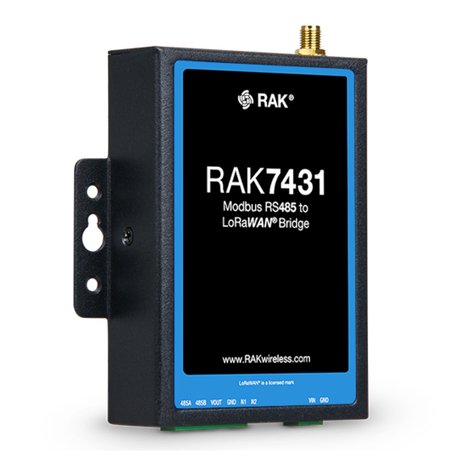
HIQUEL SLS-500-MBUS-MODBUS Series Instructions for use

HIQUEL HIQUEL-MBUS-Konverter
HIQUEL-MBUS-
Converter
Hardware- user manual

HIQUEL HIQUEL-MBUS-Konverter
Seite 2 von 21
Maurer Helmut, Manuel Niederl, Herbert Weiß
HIQUEL-MBUS-Configurator– Software - User Manual
Version: 2.00
Great care has been taken in the creation of the text, illustrations
and program examples in this manual. The editors and
publishers accept no responsibility for any inadvertent omission
of entries or for typographical or other errors herein. Nor can they
be held responsible or liable for consequences arising from any
errors herein.
This manual is subject to copyright law. All rights are reserved.
This manual may not be copied in part or whole in any form
including electronic media without the written consent of
HIQUEL. Neither may it be transferred in any other language
suitable for machines or data processing facilities. Also rights for
reproduction through lecture, radio or television transmission are
reserved.
This documentation and the accompanying software are
copyrighted by HIQUEL.
©Copyright 2005 – 2007 by HIQUEL GmbH
‘Windows’ and ‘Microsoft’ are registered trademarks of Microsoft
Corporation. ‘Pentium’ is a registered trademark of Intel
Corporation. ‘Adobe’, ‘Acrobat’, ‘Acrobat Reader’ and the ‘Adobe
Logo’ are registered trademarks of Adobe System Incorporated.
All other trademarks mentioned and shown in the text are
trademarks of their owners and are patented that way

HIQUEL HIQUEL-MBUS-Konverter
Seite 3 von 21
History
Datum Author Description
30.06.06 O. Reisky First version
27.09.06 H.Weiß Add-on of the function query pause
15.12.06 H.Weiß Add-on of the tested counters
05.03.07 M. Niederl Add-on of the tested counters
16.01. 08 M. Niederl Discription of the system registers

HIQUEL HIQUEL-MBUS-Konverter
Seite 4 von 21
Caution!
You are handling dangerous
electrical current!
Disconnect the supply voltage before making any wiring
modifications.
Ensure that the system cannot be switched on accidentally.
Ensure that the device and its surroundings are potential free.
Please refer to the specific installation and mounting instructions.
Qualified personal only should handle the device.
The device has to be mounted in such a way that no unintentional
operation may occur.
All control and supply voltage wiring must be routed so that no
inductive or capacitive interference or any other severe electrical
noise disturbance may interfere with the device.
Supply voltage variation must not exceed the specifications in the
technical details. If so, proper performance of the device cannot be
guaranteed.
Emergency installations according to EN60204/IEC204 (VDE0113)
must remain active in all modes of the automated installation.
Activation of the emergency installation must not cause an
uncontrolled or undefined start cycle.
The software engineer has to make sure, that no failure functions
of the automated installation may occur when line faults or core
faults arise.
Notwithstanding the above, local regulations must be observed in
all installations.

HIQUEL HIQUEL-MBUS-Konverter
Seite 5 von 21
Safety-related advice
Danger to life through electrical current!
Only skilled personal trained in electro-engineering should perform
the described steps in the following chapters. Please observe the
country specific rules and standards for the mini module
installation. Do not perform any electrical work while the device is
connected to power!
Please pay attention to the following rules:
Activate the automated installation
Disable any automatic restart system.
Electrically isolate the installation
Cover any non-isolated areas

HIQUEL HIQUEL-MBUS-Konverter
Seite 7 von 21
Introduction
Since the data from SLS-500-MBUS-MODBUS Converters can be
read from any Modbus-Master (automated control, visualisation
system etc...) a very broad range of applications becomes
possible. For instance data from a heat meter can be easily
represented on a mimic display. Each MBUSMODBUS Converter
module can read the data from up to 8 Meter bus unit loads ( 1 unit
load corresponds to 1,5 mA current consumption of one
participant). Thus maximal 8 devices each one unit load can be
connected to one MBUS-MODBUS Converter. The current
consumption of a device can be seen from the respective data
sheet.
The data to be read are freely configurable and are automatically
actualised in selectable periods of time.
•meter-Bus ports for max. 8 unit loads (1,5 mA)
•meter-Bus interface: 300 to 38400 bps, 8 data bits, even
parity, 1 stop bit
•meter-Bus and Modbus interfaces are galvanically isolated
•Modbus interface: RS232 or RS485, 9600 to 57600 bps, 8
data bits, no parity, 1 stop bit
•Modbus address and enquiry interval selectable
•Configuration of max. 100 Meter-Bus values
•4 different data formats for the representation of the values in
the modbus registers
•supply voltage 24 V DC
type part number supply weight
SLS-500-MBUS-
MODBUS-RS232 Meter-Bus to Modbus Converter
with RS232 interface 24 V= 85 g
SLS-500-MBUS-
MODBUS-RS485 Meter-Bus to Modbus Converter
with RS2485 interface 24 V= 85 g

HIQUEL HIQUEL-MBUS-Konverter
Seite 8 von 21
Specification
supply voltage 24 V= operating conditions -40...85 °C
power consumption 1 VA Tolerable humidity 10...90 % rH non
condensing
degree of protection IP20 (EN 60529)
Modbus interface protection class IP20
protocol Modbus/RTU
type RS232 or RS485 block connection
diagram Figure 4-1
9600 to 57600 / 8 / N / 1 dimensions - graphic Figure 6-1
dimensions B x H x T 22,5 x 85 x 70
Meter-Bus interface
max. unit loads 8
300 to 38400 / 8 / E / 1 factory settings Modbus Address
255
Modbus baud
rate: 19200
ternimals M-Bus baud rate:
300
max. terminal cross
section 2,5 mm² rigid
1,5 mm² flexible CE conformity YES
Accessories
SLS-500-MBUS-
Configurator configuration software tool for SLS-500-MBUS-MODBUS-
converter

HIQUEL HIQUEL-MBUS-Konverter
Seite 9 von 21
Block connection diagram
Description
version with RS232 connection version with RS485 connection
Figure 4-1: Description of terminals and indications.
SLS-500-MBUS-MODBUS-
RS232 SLS-500-MBUS-MODBUS-
RS485
A supply voltage
L+: 24 V=; M-: ground supply voltage
L+: 24 V=; M-: ground
B RS232 Modbus interface
Rx: receiving data
Tx: sending data
RS485 interface
A: positive data link
B: negative data link
C Meter-Bus interface
MBus+; MBus- Meter-Bus interface
MBus+; MBus-
D indication of the status of the
converter indication of the status of the
converter
E indication for supply voltage of
the M-Bus interface indication for supply voltage of
the M-Bus interface
F Indication for sending data on the
M-Bus interface Indication for sending data on
the M-Bus interface
G Indication for receiving data on
the M-Bus interface Indication for receiving data
on the M-Bus interface
Table 4-1 Description of terminals and indications

HIQUEL HIQUEL-MBUS-Konverter
Seite 10 von 21
Connection block diagram
PC,
PLC,
Touch Panel,
etc.
+24V= Tx
Rx
RS232
M-Bus meter
(1,5 mA load)
M+ M-
M-Bus meter
(1,5 mA load)
M+ M-
M-Bus meter
(1,5 mA load)
M+ M-
GND
< 3 A
Up to 8 separate M-Bus meters 1,5 mA each can be connected per HIQUEL-MBUS-
MODBUS Converter

HIQUEL HIQUEL-MBUS-Konverter
Seite 11 von 21
PC,
PLC,
Touch Panel,
etc.
+24 V=
GND A
B
M-Bus meter
(1,5 mA load)
M+ M-
RS485
M-Bus meter
(1,5 mA load)
M+ M-
M-Bus meter
(1,5 mA load)
M+ M-
< 3 A
Up to 8 separate M-Bus meters 1,5 mA each can be connected per HIQUEL-MBUS-
MODBUS Converter

HIQUEL HIQUEL-MBUS-Konverter
Seite 12 von 21
Description of the
functions
The SLS-500-MBUS-MODBUS converter automatically reads
preconfigured values from MBUS meters and makes them
available in Modbus holding registers. Up to 100 values can be
read via Modbus.
On application of the supply voltage the converter verifies if a valid
configuration is available or not. If so, the converter starts to
initialise all MBUS meters. If no answer is received from an MBUS
device within three consecutively initialising attempts it is skipped
and the next meter is initialised. The initialising procedure is
repeated every 5 query cycles. After a pause of 5 seconds the first
query cycle begins.
The values of all initialised devices are read and depending on the
configuration written into the respective Modbus registers. From
now on the selectable pause time between two query cycles is
activated.
If no answer is received from an initialised MBUS device within
three consecutively reading attempts, this device is reinitialised
within the following working cycle. After three failed initialising
attempts, another attempt follows every 5 cycles. After successful
initialisation the data are read in the following cycle.
Most of the MBUS slaves actualise their values only after a query
has been performed. As the converter allows the definition of
pauses between queries to up to 18 hours, the following
mechanism avoids that ‘old’ values are read:
If pauses between queries are longer that 30 seconds, the
converter requests all slaves 30 seconds before the real query to
actualise their values.
For communication via Modbus the following functions are
available:
•READ HOLDING REGISTER (function code: 3)

HIQUEL HIQUEL-MBUS-Konverter
Seite 13 von 21
•PRESET SINGLE REGISTER (function code: 6)
•PRESET MULTIPLE REGISTERS (function code: 16)
Note: The functions READ HOLDING REGISTER and PRESET
MULTIPLE REGISTERS are limited to max. 50 register per query!
Overview of the registers:
Modbus address 4x00001
Modbus baud rate
4x00001 Meter-Bus baud rate
pause between queries 4x00004
4x00005
4x00207
configuration Data points’ list
4x00204
store configuration 4x00205
4x00208 restart converter 4x00206
4x00300
unused
Software version 4x00301
4x00301 Error code
device status
4x00328 system device #1…#8
4x00260 Identification number
device #1…#8 4x00328
4x00500
unused
4x00501
4x00700
value’s list
4x00701
4x65535
unused
All unused register read out the value 0.

HIQUEL HIQUEL-MBUS-Konverter
Seite 14 von 21
System registers:
Version of the converter software
Error code
Device status
Register Short name type address
Start
value
Software version SWVERSION read 4x00301 -
Error code ERRCODE read 4x00302 -
status device 1 SLAVESTATE1 read 4x00303 -
status device 2 SLAVESTATE2 read 4x00304 -
status device 3 SLAVESTATE3 read 4x00305 -
status device 4 SLAVESTATE4 read 4x00306 -
status device 5 SLAVESTATE5 read 4x00307 -
status device 6 SLAVESTATE6 read 4x00308 -
status device 7 SLAVESTATE7 read 4x00309 -
status device 8 SLAVESTATE8 read 4x00310 -
4x00311 –
4x00312 0
ID device 1 SLAVEID1 read 4x00313 -1
ID device 2 SLAVEID2 read 4x00315 -1
ID device 3 SLAVEID3 read 4x00317 -1
ID device 4 SLAVEID4 read 4x00319 -1
ID device 5 SLAVEID5 read 4x00321 -1
ID device 6 SLAVEID6 read 4x00323 -1
ID device 7 SLAVEID7 read 4x00325 -1
ID device 8 SLAVEID8 read 4x00327 -1

HIQUEL HIQUEL-MBUS-Konverter
Software version:
SWVERSION Holding Register (4x00301) factory setting: -
15 14 13 12 11 10 9 8 7 6 5 4 3 2 1 0
MAJOR MINOR RELEASE
bit description
MAJOR main version
range: 0 to 15
MINOR secondary version
range: 0 to 15
RELEASE issue
range: 0 to 255
Error code:
ERRCODE Holding Register (4x00302) factory setting: -
15 14 13 12 11 10 9 8 7 6 5 4 3 2 1 0
ERROR CODE
bit description
ERROR CODE Error code
0: no error
1: no valid configuration
2: error in configuration
3: system error

HIQUEL HIQUEL-MBUS-Converter
Seite 16 von 21
State device x:
SLAVESTATEx Holding Register
(4x00303...4x00310) factory setting: -
15 14 13 12 11 10 9 8 7 6 5 4 3 2 1 0
SLAVEADR SLAVESTATE
bit description
SLAVEADR Meter-Bus address of the device
range: 0 to 255
SLAVESTATE device state
0: not configured
1: ready for initialisation
2: send the initialisation
3: wait for answer
4: ready for data exchange
5: send the query
6: wait for answer

HIQUEL HIQUEL-MBUS-Converter
Seite 17 von 21
Identification number device x:
The identification number is derived from the M-Bus protocol
header and is stored as a signed 32-bit binary number in 2 Modbus
registers.
SLAVEIDx (1. Register) Holding Register
(4x00313, 4x00315, ... ,
4x00327)
factory setting: -
15 14 13 12 11 10 9 8 7 6 5 4 3 2 1 0
SLAVEID LOW WORD
SLAVEIDx (2. Register) Holding Register
(4x00314, 4x00316, ... ,
4x00328)
factory setting: -
15 14 13 12 11 10 9 8 7 6 5 4 3 2 1 0
SLAVEID HIGH WORD

HIQUEL HIQUEL-MBUS-Converter
Seite 18 von 21
Technical Data
Dimensions
Figure 6-1 Housing type – dimensions in mm.
dimensions
installation dimensions B x H x T (mm) 22,5 x 85 x 70
weight 85 g
colour grey (RAL 7012)
material Noryl®(housing)
Wellamid®(terminals)
Lexan®940A (cover plate)
protection class IP20 after DIN 40050/EN 60529
Table 6-1 Specification of the housing.

HIQUEL HIQUEL-MBUS-Converter
Seite 19 von 21
Electrical data
voltage, current, temperature
supply voltage
nominal voltage 24 V=
voltage range 18 V= to 30 V=
current drain typically 36 mA=
max. 55 mA=
max. switch-on current 100 mA= (20 ms)
operating conditions 0 °C to 60 °C
storage temperature -20 °C to 85 °C
humidity in the air (non condensing) 10...90 % rH
protection class IP20
CE conformity YES
Table 6-2: General electrical data.
terminals
clamp acquirement 1*
screw tightening torque 0,4. 0,8 Nm
screws pozidrive 1,slot 3,5*0,6mm
Table 6-3: Specification of the terminals.
Modbus interface
physics RS232 / RS485
carrying out terminals
electrical isolation no
power supply for external devices no
status indication no
settings 9600 to 57600 baud, 8 data bits, no
parity, 1 stop bit
protocol Modbus / RTU
Table 6-4: Specification of the Modbus interface.
1*
1x0,25..2,5mm2with/without wire termination (cable end sleeves)
1x4mm2 without wire termination
2x0,25..1,5mm2with/without wire termination
2x2,5mm2flexible without wire termination

HIQUEL HIQUEL-MBUS-Converter
Seite 20 von 21
Meter-Bus interface
physics Meter-Bus
carrying out terminals
electrical isolation to the supply voltage and the Modbus
interface
power supply for external devices max. 8 devices á 1,5 mA per participant
status indication send and receive
settings 300 to 38400 baud, 8 data bits, even parity,
1 stop bit
protocol Meter-Bus
cable (according to M-Bus standard) YSLY-J n x 2 x 0,8 mm
max. cable length 350 m
max. cable capacity 180 nF
Table 6-5: Specification of the Meter bus interface.
Appendix
Tested meters
The following meters were tested in house for proper function in
combination with our converter:
manufacturer meter from software version
Kamstrup Multical® 401 1.0.0
Zenner Zähler multidata S1 2.0.0
Engelmann
ista (viterra Energy Services) sensonic®
Sensostar® 2.0.4
Kamstrup Multical® III 2.0.0
Schrack (EMH) MG DIZ305 2.0.0
ABB Deltaplus 2.0.4
Kamstrup Multical® 2.0.4
Kamstrup Multical®_Compakt 2.0.4
Actaris Cyble MBus
Table 6-6: List of tested MBUS meters.
This manual suits for next models
2
Table of contents
Popular Media Converter manuals by other brands
Allied Telesis
Allied Telesis Converteon AT-CV5M02 datasheet
TANDBERG
TANDBERG E5714 DSNG Voyager reference guide
cybernetech
cybernetech CT-10G-MC series user manual

Tascam
Tascam IF-DA8 owner's manual

Lantronix
Lantronix M/E-TX-FX Series user guide
Speaka Professional
Speaka Professional 1000179 operating instructions

