Hirose HRS DH Series User manual

取扱説明書
INSTRUCTION MANUAL
DH シリーズ結線治具/
DH Series Connection Jigs
※TAD-P0121 第3版/
Third edition
安全に使用していただくために、使用前に必ずこの取扱説明書をお読みください。
また、いつでもすぐに読めるように、この取扱説明書を保管してください。
注意
CAUTION :
Be sure to read this Instruction Manual carefully before using it to secure safety in operation.
In addition, save this Instruction Manual so that it is available whenever necessary for review.
Dec.1.2023Copyright2023HIROSEELECTRICCO.,LTD.AllRightsReserved.

はじめに
この度は、DH シリーズ結線治具をご購入いただき、誠にありがとうございます。
本書は、DH コネクタを結線する手順および工具の取扱説明書です。
ご使用前に必ず本書をよくお読みいただき十分ご理解の上、正しくご使用くださいますようお願いい
たします。
PREFACE
Thank you very much for your purchase of our DH Series Connection Jigs.
This Manual describes the procedure for connecting the DH connectors and the details of the tool.
Be sure to read this Instruction Manual carefully before using it to secure safety in operation.
Dec.1.2023Copyright2023HIROSEELECTRICCO.,LTD.AllRightsReserved.

- i -
安全にご使用していただくために
本工具を実際にご使用されるオペレータの方、および保守・修理などをされる保全の
方は、以下の安全についての注意事項を熟読されて、怪我などされないようにご使
用ください。
なお、本取扱説明書および警告表示の内容を十分に理解し、指示を守ってください。
(I )警告表示の説明
危険
取り扱いを誤った場合に、使用者が死亡または重傷を負う危険
が切迫して生じることが想定される場合。
警告
取り扱いを誤った場合に、使用者が死亡または重傷を負う可能
性が想定される場合。
注意
取り扱いを誤った場合に、使用者が傷害を負う危険が想定され
る場合および物的損害のみの発生が想定される場合。
※損害の程度の分類は、以下を参考とする。
重傷: 失明,けが,やけど(高温・低温),感電,骨折,中毒などで、後遺
症が残るもの。
および治療に入院・長期の通院を要するものを言う。
傷害: 治療に入院や長期の通院を要さない、けが,やけど,感電などを指す。
物的損害 : 家屋・家財および家畜・ペットにかかわる拡大損害を指す。
安全についての注意事項
基本的注意事項
1. ご使用される前に本取扱説明書、および付属に入っている全ての説明書類を必ず
お読みください。また、いつでもすぐに読めるように、この取扱説明書を大切に
保存してください。
安全装置
1. 本工具には、安全カバーなどの安全装置は取り付いていません。結線作業に際し
ては、ハンドル部に指など挟まないよう安全に十分配慮してご使用ください。
用途
1. この工具は、本来の用途および本取扱説明書に規定された使用方法以外には使用
しないでくだい。用途以外の使用に対しては、当社は責任を負いません。
2. 工具には、改造などを加えないでください。改造によって起きた事故に対して
は、当社は責任を負いません。
保守
1. 不慣れによる事故を防ぐため、修理・調整は工具を熟知した保全技術者が本取扱
説明書の指示範囲で行ってください。不適切な修理・調整および非純正部品によ
る事故に対しては、当社は責任を負いません。
2. 人身事故を防ぐため、修理調整・部品交換などの作業後は、ねじ・ナットなどが
ゆるんでいないことを確認してください。
3. 工具の使用期間中は、定期的に清掃を行ってください。
4. 事故を防ぐため、修理・調整した結果、正常に動かない場合は直ちに操作を中止
し、当社に連絡し修理依頼してください。
注意
Dec.1.2023Copyright2023HIROSEELECTRICCO.,LTD.AllRightsReserved.

- ii -
FOR SAFE OPERATION
The operators of the tool and the maintenance personnel who are in charge of maintenance and repair work are
required to read the following SAFETY INSTRUCTIONS.
Fully understand and follow the descriptions given in this Instruction Manual and the warning symbols attached
to the tool.
(I) Description of warning messages
DANGER
Misuse of the tool will expose the operator to immediate danger of
major injury or death.
WARNING
Misuse of the tool may expose the operator to danger of major injury
or death.
CAUTION
Misuse of the tool may expose the operator to danger of injury and may
cause damage to property.
* Determine the degree of impairment referring to the below-stated classification.
Major injury : Loss of eyesight, wounds, burns (hyperthermal and hypothermal burns), electric shocks,
fracture of a bone, poisoning, etc. requiring emergency treatment or extended medical care.
Injury (Minor injury): Wounds, burns, electric shocks, etc. requiring medical treatment.
Damage to property : Damage to the machinery and or the surrounding area.
SAFETY INSTRUCTIONS
Basic safety instructions
1. Be sure to read understand and follow all the instructions and other materials supplied with the unit as
before using the tool. Save this Instruction Manual and make it available for review whenever necessary.
Safe operation
1. Such safety devices as the safety cover and the like are not attached to this tool. When performing
connection, use this tool while fully considering so that the fingers or the like are not caught in the
handle section.
Application
1. This tool shall only be used for its originally intended purpose while following the instructions specified
in this Instruction Manual. Hirose assumes no responsibility for any misuse of the tool other than the
intended use.
2. Modifications to this tool is prohibited. We assume no responsibility for accidents resulting from
modifications.
Maintenance
1. To prevent possible accidents caused by unfamiliarity with the operation of the tool, repair and
adjustment of the tool shall be conducted only by maintenance personnel who have a full knowledge of
the tool. Any repair and adjustment beyond the range covered by the instructions given in this
Instruction Manual is prohibited. We assume no responsibility for accidents caused by improper repair
or adjustment or the use of non-genuine part(s).
2. To protect against personal injury, check to be sure that screws and nuts are properly tightened after
the completion of repair/adjustment works or replacement of the parts.
3. Periodically cleaning of the tool is recommended.
4. In the event that your tool fails to perform normally after repair or adjusting immediately stop the work
and contact us for service so as to protect against personal injury.
CAUTION
Dec.1.2023Copyright2023HIROSEELECTRICCO.,LTD.AllRightsReserved.

- iii -
目次
1. 仕様と構成...................................................................................................................1
1-1. 治具の構成 ............................................................................................................................... 1
1-2. 治具の形状および各部の名称 ............................................................................................ 3
1-3. 治具の取付方法およびラチェット調整方法.................................................................. 6
1-4. 芯数別圧接ユニットおよび金具別加締めユニットの取り付け............................... 9
2. 結線方法 ....................................................................................................................10
2-1. ケーブルの端末処理...........................................................................................................10
2-2. 整線 .........................................................................................................................................11
2-3. 圧接 .........................................................................................................................................15
2-4. ケーブル加締め....................................................................................................................18
2-5. カバー取り付け....................................................................................................................20
3. パーツの交換 ...........................................................................................................21
3-1. 圧接治具................................................................................................................................. 21
3-2. 加締め治具 ............................................................................................................................23
3-3. 加締めハイト調整方法 ......................................................................................................25
4. 保守と点検................................................................................................................26
4-1. 日常のお手入れについて..................................................................................................26
4-2. 治具取扱上の注意事項 ......................................................................................................26
4-3. コネクタ取扱上の注意事項..............................................................................................27
Dec.1.2023Copyright2023HIROSEELECTRICCO.,LTD.AllRightsReserved.

- iv -
CONTENTS
1. Specifications and configuration....................................................................2
1-1. Configuration of the jig.............................................................................................. 2
1-2. Shape and configuration of the jig............................................................................. 3
1-3. Procedures for mounting the jig and for adjusting the ratchet ................................ 6
1-4. Attaching the cold welding units for each number of conductors
and swaging unit for each metal fitting .................................................................... 9
2. Connecting method.......................................................................................10
2-1. Treating the cable terminals .................................................................................... 10
2-2. Arranging the conductors ........................................................................................ 11
2-3. Cold welding............................................................................................................. 15
2-4. Swaging the cable..................................................................................................... 18
2-5. Attaching the cover .................................................................................................. 20
3. Replacing the parts.......................................................................................21
3-1. Cold-welding jig ....................................................................................................... 21
3-2. Swaging jig ............................................................................................................... 23
3-3. Adjusting the swaging height................................................................................... 25
4. Maintenance and inspection.........................................................................26
4-1. Daily maintenance.................................................................................................... 26
4-2. Precaution to be taken when handling the jig ......................................................... 26
4-3. Precaution to be taken when handling the connector.............................................. 27
Dec.1.2023Copyright2023HIROSEELECTRICCO.,LTD.AllRightsReserved.

- 1 -
1. 仕様と構成
1-1. 治具の構成
DH30(32)B-※※Sコネクタのハーネスに必要な治具は、下記の通りです。
工程名 治工具名称 CLコード 備考
端末処理 手作業
上段整線
整線治具
DH/CA-MD CL902-2183-0 17~51 芯兼用
ケーブル圧入
(上段)
下段整線
ケーブル圧入
(下段)
ケーブル切断 手作業
(ニッパー等) (参考市販品)
スリーピークス技研 MPN-100
圧接
圧接・加締め治具本体
DH/IDCK-MP
+
各芯数別圧接ユニット
+
HI-FLEX 結線プレス
CL902-2185-5
(備考欄参照)
CL550-0082-2
17 芯:DH-17UNIT
CL902-2186-8
27 芯:DH-27UNIT
CL902-2187-0
37 芯:DH-37UNIT
CL902-2188-3
51 芯:DH-51UNIT
CL902-2189-6
クランプ
加締め
圧接・加締め治具本体
DH/IDCK-MP
+
金具別加締めユニット
+
HI-FLEX 結線プレス
CL902-2185-5
(備考欄参照)
CL550-0082-2
CMB(5.6):DH-17-CMB(5.6)UNIT
CL902-2197-4
CMB(6.3):DH-17-CMB(6.3)UNIT
CL902-2190-5
CMB(6.6):DH-17-CMB(6.6)UNIT
CL902-2196-1
CMB(6.9):DH-27-CMB(6.9)UNIT
CL902-2194-6
CMB(7.3):DH-27-CMB(7.3)UNIT
CL902-2191-8
CMB(7.8):DH-37-CMB(7.8)UNIT
CL902-2198-7
CMB(8.8):DH-37-CMB(8.8)UNIT
CL902-2192-0
CMB(9.0):DH-51-CMB(9.0)UNIT
CL902-2199-0
CMB(9.6):DH-51-CMB(9.6)UNIT
CL902-2193-3
カバー取付 手作業
(トルクドライバー等)
Dec.1.2023Copyright2023HIROSEELECTRICCO.,LTD.AllRightsReserved.

- 2 -
1. Specifications and configuration
1-1. Configuration of the jig
The following jigs are necessary for the DH30 (32) B-**S connector harness.
Name of process
Name of jig
CL code
Remarks
Terminal treatment
Manual work
Arrangement of
conductors on upper
stage of keep plate
Jig for arranging
conductors
DH/CA-MD
CL902-2183-0 Commonly used for 17- to 51-
conductor cables
Press-fitting of
conductors (upper
stage)
Arrangement of
conductors on lower
stage of keep plate
Press-fitting of
conductors (lower
stage)
Cutting of cable Manual work (with a
pair of nippers, etc.)
(Commercially-available product for
reference) MPN-100 made by
THREE PEAKS GIKEN CO., LTD.
Cold welding
Main body of jig for
cold welding and
swaging
DH/IDCK-MP
+
Cold welding units for
each number of
conductors
+
HI-FLEX connection
press
CL902-2185-5
(Refer to the
"Remarks" column.)
CL550-0082-2
17-conductor : DH-17UNIT
CL902-2186-8
27-conductor : DH-27UNIT
CL902-2187-0
37-conductor : DH-37UNIT
CL902-2188-3
51-conductor : DH-51UNIT
CL902-2189-6
Swaging of clamps
Main body of jig for
cold welding and
swaging
DH/IDCK-MP
+
Swaging unit for each
metal fitting
+
HI-FLEX connection
press
CL902-2185-5
(Refer to the
"Remarks" column.)
CL550-0082-2
CMB(5.6)
:
DH-17-CMB(5.6)UNIT
CL902-2197-4
CMB(6.3):DH-17-CMB(6.3)UNIT
CL902-2190-5
CMB(6.6):DH-17-CMB(6.6)UNIT
CL902-2196-1
CMB(6.9):DH-27-CMB(6.9)UNIT
CL902-2194-6
CMB(7.3):DH-27-CMB(7.3)UNIT
CL902-2191-8
CMB(7.8):DH-37-CMB(7.8)UNIT
CL902-2198-7
CMB(8.8):DH-37-CMB(8.8)UNIT
CL902-2192-0
CMB(9.0):DH-51-CMB(9.0)UNIT
CL902-2199-0
CMB(9.6):DH-51-CMB(9.6)UNIT
CL902-2193-3
Attaching of cover
Manual work (Torque
screwdriver, etc.)
Dec.1.2023Copyright2023HIROSEELECTRICCO.,LTD.AllRightsReserved.
- 3 -
1-2. 治具の形状および各部の名称/Shape and configuration of the jig
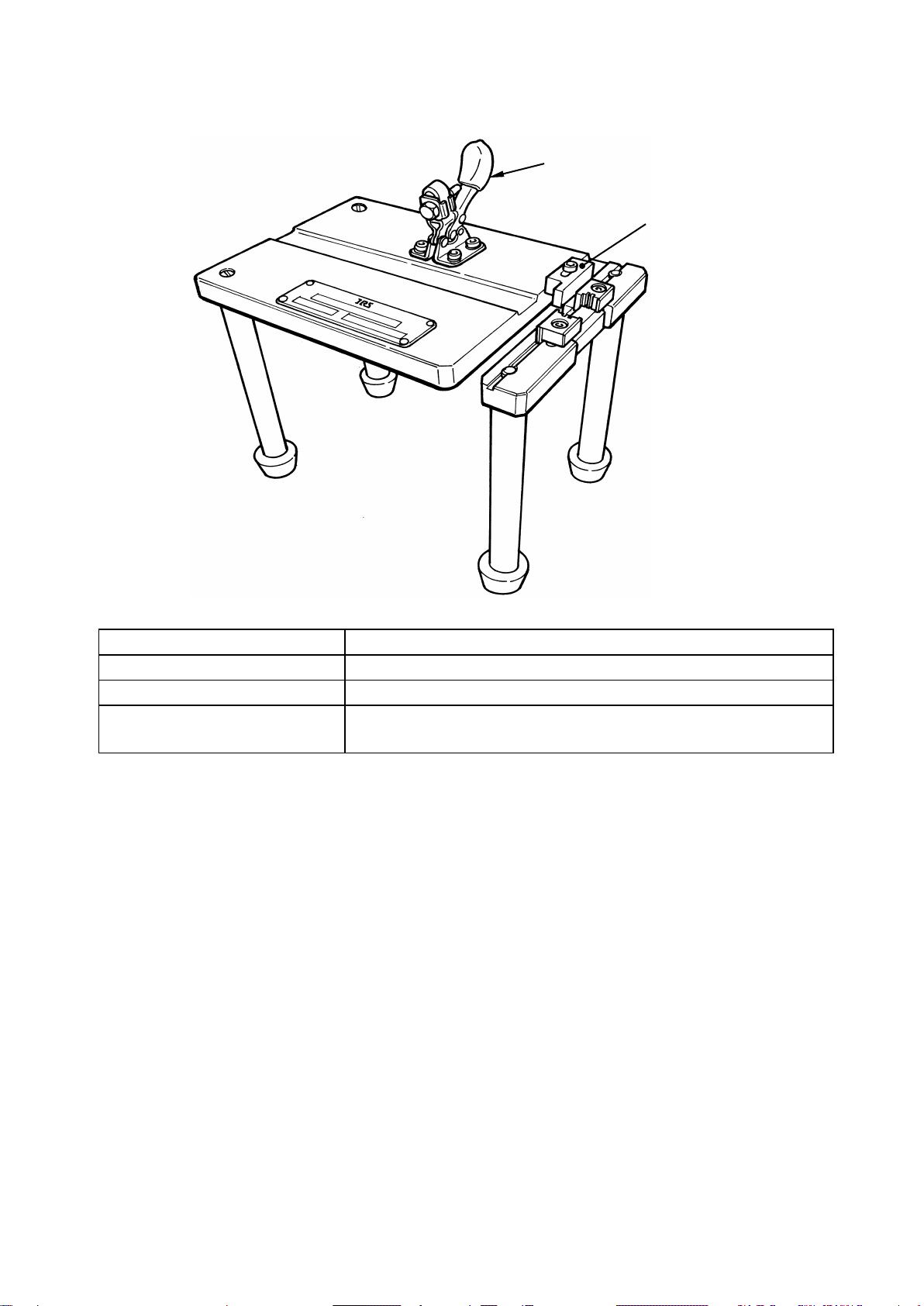
(1) 整線治具DH/CA-MD/Jig for arranging conductors DH/CA-MD
■仕様/Specifications
製品名/Name of product DH/CD-MD
HRS No. CL902-2183-0
外形寸法/External dimensions 150×100×125
用途/Application 押え板およびケーブルのセット保持/
For setting and retaining of keep plate and cables
ケーブルストッパー
Cable stopper
トグルクランプ
Toggle clamp
Dec.1.2023Copyright2023HIROSEELECTRICCO.,LTD.AllRightsReserved.

- 4 -
(2) 結線プレス/Connection press
この結線プレスは、Hi-Flex シリーズコネクタ全機種の結線作業にご使用できます。
The connection press is applicable for connecting all types of the Hi-Flex Series connectors.
(3) 圧接・加締め治具本体DH/IDCK-MP/Main body of jig for cold welding and swaging DH/IDCK-MP
■仕様/Specifications
製品名/Name of product DH/IDCK-MP
HRS No. CL902-2185-5
外形寸法/External dimensions 125×125×50
用途/Application 圧接,加締めの治具本体/
Main body of jig for cold welding and swaging
備考/Remarks
圧接:DH-※※UNIT と合わせて使用/
Cold welding: To be used in combination with DH-** UNIT
加締め:DH-※※-CMB(**)UNIT と合わせて使用/
Swaging: To be used in combination with DH-**-CMB (**) UNIT
HRS No. 製品番号
Product number
高さ
Height
幅
Width
奥ゆき
Depth
重量
Weight
550-0082-2 Hi-Flex 結線プレス
Hi-Flex Connection press
440mm 160mm 350mm 13kg
各部の名称/
Name of parts
A:加圧ブロックの取付部/Pressure-block mounting section
B:ガイドプレート取付部/Guide-plate mounting section
C:ラチェット部/Ratchet section
D:ハンドル部/Handle section
A
B
C
D
Dec.1.2023Copyright2023HIROSEELECTRICCO.,LTD.AllRightsReserved.

- 5 -
(4) 各芯数別圧接ユニット DH-※※UNIT/
Cold welding units for each number of conductors DH-**UNIT
(5) 金具別加締めユニット DH-※※-CMB(**)UNIT/
Swaging unit for each metal fitting DH-**-CMB(**)UNIT
Dec.1.2023Copyright2023HIROSEELECTRICCO.,LTD.AllRightsReserved.

- 6 -
1-3. 治具の取付方法およびラチェット調整方法/
Procedures for mounting the jig and for adjusting the ratchet
(1) 加圧ブロックの取り付け/Mounting the pressure block
2)
次に M5 六角レンチ(本休プレス附属
品)をロックナット穴部(D)に差し込み、
ブロックホルダーに表示(刻印)されてい
るL方向に回して加圧ブロックを締めつ
けてください。(図 1-3-2 参照)
2) Insert the M5 hexagonal wrench key (supplied
with the main body of press as an accessory)
into the hole (D) and turn it in direction L
indicated (by inscription) on the block holder
to secure the pressure block. (See Fig. 1-3-2)
1) 取り付ける場所および向きは、図 1-3-1
および図 1-3-2 を参照してください。
加圧ブロック取付部のブロックホルダー凹
部(A)に加圧ブロックの凸部(B)をはめこ
んでください。
1) Refer to Fig. 1-3-1 and Fig. 1-3-2 for the
installing location and orientation.
Fit the projected part (B) of the pressure block
into the recessed part (A) of the block holder
at the pressure-block mounting section.
加圧ブロックホルダー凹部
(
A
)
Recessed part (A) of
pressure block holder
加圧ブロック凸部
(
B
)
Projected part (B)
of pressure block
加圧ブロック
(
C
)
Pressure block (C)
加圧ブロックホルダー
Pressure block holder
ロックナット
Locknut
図1-3-1/
Fig. 1-3-1
図1-3-2/Fig. 1-3-2
ブロックホルダー
Block holder
加圧ブロック
Pressure block
M5六角レンチ
M5 Hexagon
wrench key
ロックナット穴部
(
D
)
Hole (D) in locknut
ロックナット
Locknut
Dec.1.2023Copyright2023HIROSEELECTRICCO.,LTD.AllRightsReserved.

- 7 -
(2) ガイドプレートの取り付け/Mounting the guide plate
2) あらかじめ加圧ブロックのガイドピンがガ
イドプレートのガイドピン合せ穴に入るよ
うにプレスハンドルを下げ、ハンドルを軽
く押したまま M5 六角穴付ボルトを(a)―
(c),(b)―(d)と対角に差し込み、M5
六角レンチで締めて固定してください。
(図 1-3-4 参照)
2) Lower the press handle so that the guide pin
of the pressure block is fit in the guide-pin
guide hole of the guide plate in prior. Then,
insert M5 hexagon socket head bolt diagonal
position with respect to (a) - (c) and (b) - (d)
with the handle held pressed lightly.
Then, secure the bolt using an M5 hexagonal
wrench key. (See Fig. 1-3-4.)
1) 結線プレスのガイドプレート取付部の(A)
(B) (C) (D)取付穴(図 1-3-3 参照)
に、ガイドプレートの(a) (b) (c) (d)取
付穴(図 1-3-4 参照)を合せてくださ
い。
1) Align (a), (b), (c) and (d) of the guide plate
(see Fig. 1-3-4) with the mounting holes (A),
(B), (C) and (D) of the guide-plate mounting
section of the connection press (see Fig. 1-3-
3).
図1-3-3/Fig. 1-3-3
(C
)
(B
)
(A
)
(D
)
土台
Base
図1-3-4/
Fig. 1-3-4
ガイドピン
Guide pin
ガイドピン合せ穴
Guide
-pin guide hole
ガイドプレート
Guide plate
ガイドピン
Guide pin
(b
)
(c
)
(d
)
(a
)
Dec.1.2023Copyright2023HIROSEELECTRICCO.,LTD.AllRightsReserved.

- 8 -
(3) ラチェットの調整方法/Adjusting the ratchet
このラチェット機構は結線時に確実に結線されるまでプレスのハンドルが戻らなくなることにより、
ハンドルの加圧不足による結線不足を防止する補助装置です。調整済で出荷いたしますが、調整の
必要が出た場合には次の要領でお願いします。
図1-3-5 のラチェット解除位置調整ボルトをゆるめ、ラチェットを矢印方法に微少に動かして調
整ボルトを仮締めし、結線時の解除状態を確認しながら固く締め付けてください。
The ratchet mechanism is an auxiliary device which prevents the press handle from returning to its home
position during the connecting procedure until the connector is securely connected, thereby avoiding loose
connection resulting from inadequate pressurization of the handle. The ratchet has been factory-adjusted at
the time of delivery. In case the ratchet needs adjustment, follow the procedure described below.
Loosen the ratchet release-position adjusting bolt, shown in Fig. 1-3-5, and delicately move the ratchet in the
direction of the arrow to temporarily tighten the adjusting bolt. From this state, securely tighten the bolt while
checking how the ratchet is released.
調整の際、次の事項もご注意ください。
1) プレスのハンドルを途中まで押し下げて途
中でハンドルを元に戻したい場合(ラチェ
ットを途中で解除したい場合)、指先でツ
メに取り付けられているピンを押しながら
ハンドルを少し下げてください。ラチェッ
トが解除され、ハンドルは元に戻ります。
2) ハンドルを押し下げている途中で元に戻す
時(ラチェットが解除されないまま)、無
理な力で持ち上げないでください。ラチェ
ット部の破損原因となります。
During the adjustment, also check the following
carefully.
1) When you want to return the handle to its
home position before fully depressing the
press handle (i.e., when you want to release
the ratchet midway), slightly depress the
handle while pressing the pin mounted on the
claw with your fingertips. This will release the
ratchet to allow the handle to return to its
home position.
2) When you want to return the handle to its
home position while depressing the handle
(without releasing the ratchet), do not lift up
the handle forcibly. This can cause a break in
the ratchet section.
ツメ解除ピン
Claw release pin
ツメ
Claw
ラチェット
Ratchet
ラチェット解除位置
調整ボルト
Ratchet release
position
adjusting bolt
図1-3-5/Fig. 1-3-5
Dec.1.2023Copyright2023HIROSEELECTRICCO.,LTD.AllRightsReserved.

- 9 -
1-4. 芯数別圧接ユニットおよび金具別加締めユニットの取り付け/
Attaching the cold welding units for each number of conductors and swaging unit
for each metal fitting
1) 芯数に適合した圧接ユニットを取り付けま
す。
1) Install the cold welding unit which matches the
number of conductors.
2)
金具に適合した加締めユニットを取り付け
ます。
2) Install the swaging unit which matches the
metal fitting.
(注意) 圧接ユニットおよび加締めユニットの詳細については、「3. パーツの交換」をご参照く
ださい。
(Caution) Refer to "3. Replacing the parts" for details of the cold welding unit and swaging unit.
Dec.1.2023Copyright2023HIROSEELECTRICCO.,LTD.AllRightsReserved.

- 10 -
2. 結線方法/Connecting method
結線時に結線手順書「ATA D-E2897」を併せてご確認下さい。
Please confirm cable assembly procedure 「ATAD -E2897」during cable assembly.
2-1. ケーブルの端末処理/Treating the cable terminals
1)
ケーブル先端部の外被を剥離します。
(推奨値 70mm)
2) シールドを約6mm 残し切断します。
(注意)
この時、ケーブルに傷を付けないよ
うに注意してください。ケーブルの
傷は、ショートなどの不良の原因に
なります。
1) Peel off the jacket at the top end of the
cable. (Recommended value: 70 mm)
2) Cut out the peeled jacket with the shield
remained by approximately 6 mm.
(Caution) During the aforementioned
procedure, take care not to damage
the cable. Damaged cable can cause
failures such as a short circuit.
3) シールド部を外被側に折り返し、幅約6
mm のシールド銅テープ(住友3M社製
No. 2245 または同等品)を、1.5~2巻
します。
4) ツイストペアをほぐし、芯線が真っ直ぐに
なるようしごいてください。
(注意)
芯線のほぐし,しごきが充分行われ
ていないと、整線時の工数,コネク
タ首下寸法の増加につながります。
3) Fold over the shield toward the jacket. Then,
wrap shield copper tape of approximately 6
mm in width (No. 2245 made by
SUMITOMO 3M or equivalent) around the
cable by 1.5 to 2 turns.
4) Unravel conductors of twisted pair cable.
Stroke the conductors to straighten them.
(Caution) If the conductors are not sufficiently
unraveled and stroked, not only the
number of man-hours of cable
arrangement but also the under-head
dimension of connector can increase.
※上記は、一般的なツイストペアケーブルを使用の際の端末処理方法です。ツインナックスケーブ
ルをご使用の際は、端末処理方法が異なりますのでご注意ください。
* The aforementioned procedure of the terminal treatment applies to the general twisted pair cable.
When you use a twinax cable, the terminal treatment method is different from the above one. So, be
careful.
銅テープ
Copper tape
70mm
6mm
Dec.1.2023Copyright2023HIROSEELECTRICCO.,LTD.AllRightsReserved.

- 11 -
2-2. 整線/Arranging the conductors
1) 押え板の上段に、配線のパターンに従いケ
ーブルを通していきます。(左図は 27 芯
の場合です。)
(注意)
ケーブルを通す時には、押え板の向
きに注意してください。向きを間違
えると、圧接時にコネクタ本体がセ
ットできなくなります。
1) Pass the conductors on the upper stage of each
keep plate according to the wiring pattern.
(The figure given at left illustrates arrangement
of the 27-conductor cable.)
(Caution) When passing the conductors,
carefully check the orientation of the
keep plate. If the keep plate is
oriented in a wrong direction, it
cannot be placed on the main body of
connector at the time of cold welding.
(注意)
1.
この時、下段に配線するケーブルを、上
段に通すケーブルの間に入れるようにし
ておいてください。下段を整線する時に
ケーブルが絡み合って、ダンゴ状態にな
ってしまいます。
2.
ケーブルを通した押え板は、この状態の
ままでは作業中に抜けてしまう可能性が
ありますので、外被側に寄せておいてく
ださい。
(Caution)
1. At this time, the conductors to be wired
through the lower stage of keep plate
should be temporarily placed between the
conductors to be wired through the upper
stage of keep plate. If not, the conductors
can be intertangled to appear like a ball.
2. The keep plate through which the
conductors have been passed should be
shifted toward the jacket. If not, the
conductors can remove from the keep plate
during the subsequent procedure.
下段
Loewr stage
1番ピン
Pin No.1
上段
Up
per stage
2番ピン
Pin No.2
13番ピン
Pin No.13
14番ピン
Pin No.14
下段
Loewr stage
27番ピン
Pin No.27
上段
Upper stage
26番ピン
Pin No.26
15番ピン
Pin No.15
16番ピン
Pin No.16
下段整線用ケーブル
Conductors to be
arranged on the
lowe
r stage
上段整線用ケーブル
Conductors to be
arranged on the
upper stage
上段整線用ケーブル
Conductors to be
arranged on the
upper stage
Dec.1.2023Copyright2023HIROSEELECTRICCO.,LTD.AllRightsReserved.

- 12 -
2) 結線するコネクタの芯数に合わせて、ケー
ブルストッパーの向きを変えてください。
(注意)
本コネクタは 17 芯,27 芯と 37
芯,51 芯では首下寸法が異なり、異
なる芯数の状態で整線を行うと、ハ
ーネスできなくなる恐れがありま
す。
2) Change the orientation of cable stopper
according to the number of conductors of the
connector to be connected.
(Caution) These connectors vary in the under-
head dimension by the number of
conductors, 17- and 27-conductor
connectors and 37- and 51- conductor
ones. If the cables which differ in the
number of conductors are bundled,
they may not be harnessed.
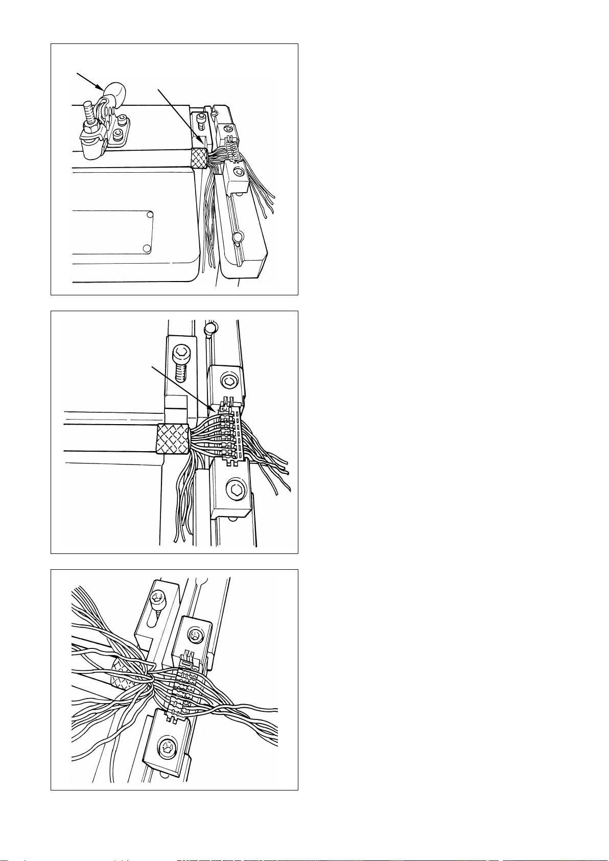
3) 整線治具のワークガイド部に、押え板の平
らな面が上を向くようにしてセットしま
す。
(注意)
押え板を治具にセットする時は、対
象の押え板上段に入っている以外の
ケーブルを整線治具本体上のスリッ
トに通し、下側に逃すようにしてく
ださい。
3) Place the keep plate (white) on the work guide
section of the arrangement jig so that the flat
surface of the keep plate faces upward.
(Caution) When placing the keep plate on the
jig, pass other conductors than those
have been passed through the upper
stage of the keep plate in concern
through the slit on the main body of
arrangement jig to route them
underside of the jig.
下側に逃がしてください
These conduc
tors should be
routed underside of the jig.
17 芯,27 芯ハーネス時
When harnessing 17
-conductor
and 27
-conductor cables
37 芯,51 芯ハーネス時
When harnessing
37-conductor
and
51-conductor cables
Dec.1.2023Copyright2023HIROSEELECTRICCO.,LTD.AllRightsReserved.
- 13 -
4)
ケーブルの外被端面がケーブルストッパー
に突き当たるまで前進させ、トグルクラン
プでその位置に固定します。
4) Move the cable forward until the end face of its
jacket is pressed against the cable stopper. Fix
the cable at that position with a toggle clamp.
5)
ケーブルを 1本づつ押え板に圧入していき
ます。
(注意)
ケーブルを圧入する際は、ケーブル
に傷を付けないように注意してくだ
さい。
5) Press-fit the conductors one after another in the
slits on the keep plate (white).
(Caution) When press-fitting the conductors in
the slits on the keep plate, be careful
not to damage the conductors.
6)
上段側の圧入が終了したらトグルクランプ
を解除してケーブルを取り出し、180 度
反転させて押え板の段が付いた側が上を向
くようにセットします。再度トグルクラン
プでケーブルを固定します。
6) After the completion of press-fitting of the
conductors on the upper stage of the keep plate
(white), release the toggle clamp to take the
cable out of the clamp. Then, turn the keep
plate upside down (i.e., turn by 180 degrees of
an angle) so that its stepped side faces upward.
Secure the cable again with the toggle clamp.
トグルクランプ
Toggle clamp
ストッパーで外被端面突き当て
The end face of jacket is pressed
against the stopper.
1本ずつ溝に圧入
Press
-fit the
conductors one by
one in the slit on
the keep plate.
Dec.1.2023Copyright2023HIROSEELECTRICCO.,LTD.AllRightsReserved.

- 14 -
7)
配線のパターン通りに、上段側も整線・圧
入を行います。
7) Arrange and press-fit the conductors on the
lower stage of the keep plate (white)
according to the wiring pattern.
8) もう一方の押え板も、同様に配線を行いま
す。
9) 両方の押え板の配線が終ったら、トグルク
ランプを解除して押え板,ケーブルを取り
出します。
8) Wire another keep plate following the similar
procedure as described above.
9) After the completion of both keep plates,
release the toggle clamp to take out the keep
plates and cables.
1本ずつ溝に圧入
Pres
s-fit the
conductors one
by one in the
slit on the keep
plate.
Dec.1.2023Copyright2023HIROSEELECTRICCO.,LTD.AllRightsReserved.
This manual suits for next models
8
Table of contents


