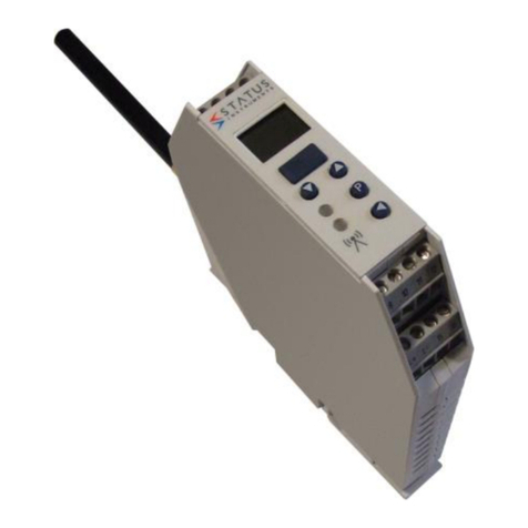
Hirschmann TRS 05 User manual

www.hirschmann.com
P/N 031-300-190-199 Revision B 09/07/2006
DS 85 with TRS 05 / PATB3
TRS 05 Receiver/PATB3 Switch Replacement on the DS 85


Installation
© Hirschmann Rev. B 09/07/2006 190199_B.DOC
1
NOTICE
Hirschmann makes no warranty of any kind with regard to this material, including, but not limited to,
the implied warranties of merchantability and/or its fitness for a particular purpose.
Hirschmann will not be liable for errors contained in this manual or for incidental or consequential
damages in connection with the furnishing, performance, or use of this manual. This document
contains proprietary information, which is protected by copyright, and all rights are reserved.
No part of this document may be photocopied, reproduced, or translated to another language without
the prior written consent of Hirschmann.
Hirschmann reserves proprietary rights to all drawings, photos and the data contained therein. The
drawings, photos and data are confidential and cannot be used or reproduced without the written
consent of Hirschmann. The drawings and/or photos are subject to technical modification without prior
notice.
All information in this document is subject to change without notice.
TABLE OF CONTENTS
1INSTALLATION............................................................................................................................... 2
1.1 TRS 05 mounting......................................................................................................................... 2
1.2 Install patch cable assembly........................................................................................................ 2
1.3 A2b switch mounting ................................................................................................................... 2
2SYSTEM DESCRIPTION................................................................................................................ 3
2.1 Receiver Module.......................................................................................................................... 3
2.1.1 LEDs .....................................................................................................................................................3
2.1.2 Control Identification .............................................................................................................................4
3OPERATION ................................................................................................................................... 5
3.1 Receiver ...................................................................................................................................... 5
4SETUP A SENSOR/MENU OPTIONS............................................................................................ 6
4.1 Install Sensor / Transmitter.......................................................................................................... 6
4.2 Uninstall Sensor / Transmitter ..................................................................................................... 7
5INSTALLATION............................................................................................................................... 8
5.1 Receiver ...................................................................................................................................... 8
6SPARE PART NUMBERS ..............................................................................................................9
© 2005 Hirschmann, Chambersburg, PA 17201, USA

Installation/Setup Manual DS 85 / TRS 05
© Hirschmann Rev. B 09/07/2006 190199_B.DOC
1 INSTALLATION
1.1 TRS 05 MOUNTING
The TRS 05 receiver will mount in the same place as the A2B receiver. Attach the 13ft long antenna
base and whip to the TRS 05; and mount the magnetic antenna parallel to the ground, as shown
below.
1.2 INSTALL PATCH CABLE ASSEMBLY
Install patch cable assembly in between the TRS05 and LMI cable harness. The patch cable connects
power, ground, and A2B signal to the TRS05 and LMI.
1.3 A2B SWITCH MOUNTING
Replace the existing switch at the boom tip with the new 6608125 radio A2B switch/transmitter,
PATB3 with the spread spectrum technology.

System Description
© Hirschmann Rev. B 09/07/2006 190199_B.DOC
3
2 SYSTEM DESCRIPTION
2.1 RECEIVER MODULE
The receiver module has the following functions:
•Visual indication of receiver power, radio links (sensor on line), sensors low battery, and alarm
conditions.
•Installs/uninstalls a sensor
•Allows a zero point and output adjustment of a load sensor.
Red Power LED
Red Alarm LED
Sensor On Line
Green LED 1
Green LED 2
Green LED 3
Green LED 4
Sensor Low Battery
Yellow LED 1
Yellow LED 2
Yellow LED 3
Yellow LED 4
2.1.1 LEDs
Red Power LED Power is applied to the circuit board.
Red alarm LED An installed sensor is indicating an alarm, or communication as been
lost to an installed sensor.
Green LED 1 ON Sensor on channel #1 is installed and communicating correctly.
Green LED 1 FLASHING Sensor #1 is not communicating correctly.
Green LED 1 OFF No sensor is installed on channel #1.
Yellow LED 1 ON Sensor #1 batteries are low and need replaced. Note that the sensor
is still operating correctly.
Green LED 2 ON Sensor #2 is installed and communicating correctly.
Green LED 2 FLASHING Sensor #2 is not communicating correctly.
Green LED 2 OFF No sensor is installed on channel #2.
Yellow LED 2 ON Sensor #2 batteries are low and need replaced. Note that the sensor
is still operating correctly.

Installation/Setup Manual DS 85 / TRS 05
© Hirschmann Rev. B 09/07/2006 190199_B.DOC
Green LED 3 ON Sensor #3 is installed and communicating correctly.
Green LED 3 FLASHING Sensor #3 is not communicating correctly.
Green LED 3 OFF No sensor is installed on channel #3.
Yellow LED 3 ON Sensor #3 batteries are low and need replaced. Note that the sensor
is still operating correctly.
Green LED 4 ON Sensor #4 is installed and communicating correctly.
Green LED 4 FLASHING Sensor #4 is not communicating correctly.
Green LED 4 OFF No sensor is installed on channel #4.
Yellow LED 4 ON Sensor #4 batteries are low and need replaced. Note that the sensor
is still operating correctly.
Green Heartbeat LED This will flash during normal operation. If it is a solid or off, the
receiver has a software error or the board has a component failure.
2.1.2 Control Identification
Sensor #1 output jumper J4
Sensor #2 output jumper J3
Sensor #3 output jumper J2
Sensor #4 output jumper J1
ID button
power (red), sensor link 1-4 left
to right (green)
LEDS
1-4 left to right (yellow)
LEDS Green Heartbeat LED
(located just under radio module)
software chip
radio module 031-300-300-024
Heartbeat LED: When blinking, this small surface board mounted green LED indicates the system is
operation properly.
ID button: The red ID button, located below the software chip on the receiver board, is used to setup
the sensor transmitter to the receiver.

Operation
© Hirschmann Rev. B 09/07/2006 190199_B.DOC
5
3 OPERATION
3.1 RECEIVER
Upon switching on crane ignition switch, the system starts with an automatic test of the receiver board,
LEDs and electronic components. The red power LED should be on and the green LEDs that sensors
have been linked to should also be on.
If an alarm condition exists investigate and clear the condition before operation and using the system.
During the normal operation of the system, the POWER and SENSOR ON LINE (if linked to a sensor)
LEDs should be on.
POWER LED
The POWER LED shows that the receiver is getting power from the crane. The receiver is on any time
the crane is operating and supplying power to the system.
SENSOR ON LINE LED
The SENSOR ON LINE LED indicates the status of communication of the transmitter(s). During
normal operation of the system, the LED will be on. The LED will flash if communication or
transmission between the sensor transmitter and the receiver is interrupted or lost. The system should
not be operated if the SENSOR ON LINE LED is flashing. If the LED is off no sensor is linked to this
channel.
LOW BATTERY LED
The low battery indicator (yellow LED) will light indicating that you have a limited time to operate
before the sensor battery life ends. When a low battery condition occurs, the follow 2 conditions will
exist:
1. The yellow LED will come on the TRS 05 for the sensor.
2. The signal for that sensor will cycle between input signal and max signal, which causes a
system fault and alarm for 25 seconds. The intent is to warn the operator that something is not
correct with the system. If the receiver is powered off/on and the low battery condition exists,
the signal will again cycle for another 25 seconds.
When the battery level is to the point that it is too low to operate, the system will display a loss of
communication and alarm. Use any off-the-shelf alkaline C-cells; Duracell, Eveready, etc. After
replacing the transmitter batteries, the receiver should clear the low battery indication.
ALARM LED
This LED will light simultaneously with the engaging of the lock out solenoids (if installed).

Installation/Setup Manual DS 85 / TRS 05
© Hirschmann Rev. B 09/07/2006 190199_B.DOC
Test the electronics
Cycle the power to the system, each LED on the receiver will light for 2 seconds when the system is
powered. All of the indicator lights must come on or the system is not functioning properly. If any light
does not function, do not use the system until it has been repaired.
Refer to receiver operating manual for pre-operational inspection.
If a green sensor on line LED starts to flash, this means a sensor is installed and the communication
link has been lost. When communication has been lost to a load cell, the receiver will output the
maximum voltage signal for the output sensor (9VDC).
If a low battery LED is on, replace the batteries in the linked transmitter, refer to Battery Replacement.
The TRS 05 setup/calibration procedure allows the operator to input the type of sensors being used,
and adjust the zero point and output adjustment of a load sensor. The operator must complete the
setup procedure for each sensor.
4 SETUP A SENSOR/MENU OPTIONS
While the ID button is held or in the calibration process, the sensor outputs will not correctly indicate
the status of other installed sensors. Correct operation will return when the menu is exited or
calibration process is complete or system is powered off/on.
The sensor setup and calibration is completed with the one ID button, pressing it starts the menu and
releasing the button selects the menu or action the operator want to complete. If an incorrect menu is
activated or the button is released accidentally, simply cycle the power and start over.
4.1 INSTALL SENSOR / TRANSMITTER
Press and hold the ID button for 3-5 second the 1st green LEDs will begin blinking. If the button is held
for 3-5 more seconds the 2nd LED will begin to blink, continue holding the button and the setup
program will cycle through the 4 sensor channels. When the correct LED is blinking, channel to be
installed, release the ID button, the receiver begins to search for a transmitter ID code. The green LED
will become solid when the transmitter is linked.
As the ID button is held and released at the blinking LED, the following actions will occur:
Green LED 1 Blinking: Search for / Install sensor 1. LED will turn solid when the sensor is found.
Green LED 2 Blinking: Search for / Install sensor 2. LED will turn solid when the sensor is found.
NOTE: A new sensor or transmitter maybe install over an existing link, when this occurs the previous
link and code are removed from memory and the new one stored.

Setup a Sensor/Menu Options
© Hirschmann Rev. B 09/07/2006 190199_B.DOC
7
4.2 UNINSTALL SENSOR / TRANSMITTER
If a sensor is setup on the channel the LED will be on, press and hold the ID button (16-28 seconds)
through the Install Sensor mode (blinking LEDs1-4) until the correct 1-4 LED is solid. When the correct
LED is solid, channel to be uninstalled, release the ID button. The sensor for the selected
channel/LED 1-4 will be uninstalled and the system will be in normal operating mode.
As the ID button is held (16-28 seconds) through the Install Sensor mode (blinking LEDs1-4) and
released at the solid LED, the following actions will occur:
Green LED 1 solid: Uninstall sensor 1.
Green LED 2 solid: Uninstall sensor 2.
Green LED 3 solid: Uninstall sensor 3.
Green LED 4 solid: Uninstall sensor 4.
This is a basic overview table of the menu selections fro the TRS 05. Press and hold ID button,
release the button at the desired indication (or the number seconds) defined in the following table.
NOTE: If an incorrect menu is activated or the button is released accidentally, simply cycle the power
and start over.
Menu Selection Release ID Button Indication
Indication
Starts
(Sec)
Indication
Ends
(Sec)
Install/setup sensor on channel 1 blinking green LED 1 3 6
Install/setup sensor on channel 2 blinking green LED 2 6 9
Install/setup sensor on channel 3 blinking green LED 3 9 12
Install/setup sensor on channel 4 blinking green LED 4 12 15
Uninstall a sensor on channel 1 solid LED 1 16 19
Uninstall a sensor on channel 2 solid LED 2 19 22
Uninstall a sensor on channel 3 solid LED 3 22 25
Uninstall a sensor on channel 4 solid LED 4 25 28
Set all the analog outputs for voltage 0-5V All 4 green LEDs blinking 29 32
Set all the analog outputs for 4..20ma All 4 green LEDs solid 33 36
Set all the analog outputs for voltage 1-9V All 4 yellow LEDs blinking 37 40
Set all the analog outputs for voltage 0-9V All 4 yellow LEDs solid 40 43
Calibrate load/angle sensor on channel 1 blinking yellow & green LEDs 1 43 46
Calibrate load/angle sensor on channel 2 blinking yellow & green LEDs 2 46 49
Calibrate load/angle sensor on channel 3 blinking yellow & green LEDs 3 50 53
Calibrate load/angle sensor on channel 4 blinking yellow & green LEDs 4 53 56
Service information on channel 1 blinking yellow LED 1 56 59
Service information on channel 2 blinking yellow LED 2 59 63
Service information on channel 3 blinking yellow LED 3 63 66
Service information on channel 4 blinking yellow LED 4 67 70
Exit/No action LEDs off no 71

Installation/Setup Manual DS 85 / TRS 05
© Hirschmann Rev. B 09/07/2006 190199_B.DOC
5 INSTALLATION
5.1 RECEIVER
The receiver module should be mounted so the operator can view the LEDs and setup the system for
operation. The location of the receiver should be in direct line of site of the transmitter and blocked by
as little metal as possible between the transmitter and receiver. However, in some cases the receiver
has been installed surrounded by metal and worked well. The location needs to be tested before
mounting the hardware. If the signal is lost, the box/receiver indicates a link error.
Securely attach the receiver onto a solid surface using the mounting holes.
Power cable connections are show above.
Model: PAT TRS 05
This device complies with Part 15 of the FCC rules.
Operation is subject to the following two conditions:
(1) This device may not cause harmful interference,
and (2) this device must accept interference that may
cause undesired operation.
ALARM
POWER
SENSOR LOW BATTERY
SENSOR ON LINE
1
1
2 3
23
4
4

Spare Part Numbers
© Hirschmann Rev. B 09/07/2006 190199_B.DOC
9
6 SPARE PART NUMBERS
6608124 RADIO, REVEIVER TRS05 ASSEMBLY, W/ ANTENNA
031-300-050-672
ANTENNA, 918 MHz
MAGNETICBASE 13' long
wire
031-300-050-671
ANTENNA, 918 MHz FOR
TRS05ASSEMBLY 060-576
WHIP ELEMENT
031-300-060-597 RADIO, RECEIVER, TRS05-2 SPREAD SPECTRUM

Installation/Setup Manual DS 85 / TRS 05
© Hirschmann Rev. B 09/07/2006 190199_B.DOC
Antenna spare parts reiteration
6608125 A2B Switch 031-300-050-763 Neoprene rubber gasket
031-300-050-672 ANTENNA, 918
MHz MAGNETICBASE 13ft long
wire
031-300-050-671 ANTENNA, 918 MHz
FOR TRS05ASSEMBLY 060-576 WHIP
ELEMENT
031-300-060-559 ANTENNA ASSY, 918
MHz WHIP FORLOAD CELL
031-300-050-688 ANTENNA, 918 MHz
RCL 90°
031-300-050-535 CONNECTOR, SMA RIGHT
ANGLE M/FREVERSE POLARITY
This manual suits for next models
1
Table of contents
Other Hirschmann Receiver manuals
