DELTA DORE TYMOOV IOFB User manual

EN Mechanical wired asynchronous tubular motors
TYMOOV
10FB - 20FB - 30FB

EN
2 3
Recommendations
WARNING: Important safety instructions
Incorrect installation can result in serious injuries.
Follow all instructions and retain these installation instructions for
future reference.
-TYMOOV xFB motors are designed solely for the operation of rollers
shutters for home use. For any other use, please contact our technical
department.
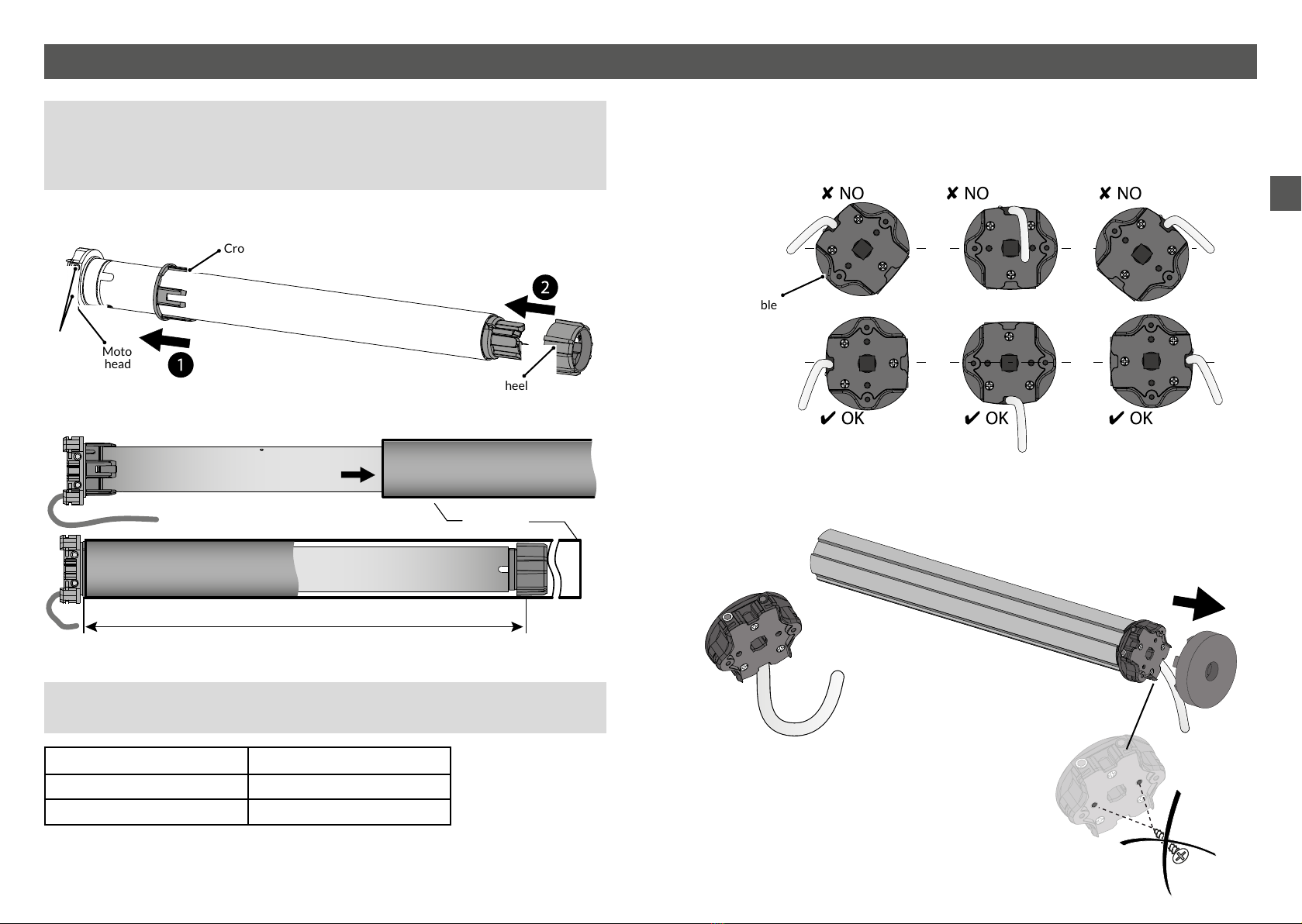
- The minimum internal diameter of the rolling tube is 47 mm,
however, the tube must be chosen according to the weight and
length of the apron. Consult the tube manufacturers’ charts.
- Do not operate the roller shutter if people or objects are within the
movement area.
- Moving parts of the motor installed at a height of less than 2.5m
must be protected.
- Before installing the motor, remove all superuous cords and take
any equipment not required for the motor to operate out of service.
- NOTE: Do not operate the shutters or cut off their power supply
when maintenance or cleaning work is being carried out on the
equipment or in close proximity (e.g. window cleaning).
- Monitor the shutter when it is moving and stand clear until it is
completely closed.
-
Do not allow children to play with the xed control devices. Keep
remote control devices out of the reach of children.
- This device can be used by children of at least 8 years of age, and by
persons with reduced physical, sensory, or mental capacities, and also
by persons lacking in experience or knowledge, provided that they are
correctly supervised or that instructions relating to the use of the safe
use of the device have been provided to them, and provided that they
understand the risks involved.
Children must not play with the device. Cleaning and maintenance by
the user must not be performed by children if unsupervised.
- The operating device for a switch without a lock must be in direct
view of the driven part, but away from the moving parts. It must be
installed at a height of at least 1.5m.
- Fixed control devices must be installed so as visible.
- During the use of a switch without a lock, make sure that all other
persons present keep their distance;
- Frequently check the equipment to detect any imbalances or signs of
wear or damage to cables and springs.
- Do not use the device when repairs or adjustments are required.
Preliminary elements
- Sufciently rigid roller shutter slats should be used.
- When the roller shutter is closed, the apron must not overlap the
runners by any more than one 1/2 slat.
- The apron clips or automatic locks used on the shutter must be used
in accordance with their manufacturer’s instructions for use.
It is essential that you adjust the number of locks based on the
model and the number of links.
- If used with upper stops, you should preferably use systems that are
built into the runners.
- Pay attention to the frame rigidity with stop systems on the shutter
slats.
Translation of the
Original Manual

EN
4 5
Recommendations
- Correct operation of the motor is ensured if it is installed and used
according to the following recommendations.
It is essential that peripheral components such as the rolling tube,
the supports, the screws etc. are appropriate and are assembled
in accordance with the latest standards. The specications of the
driven part must be compatible with the assigned load and operating
time.
- Weighted noise pressure level A: LpA ≤ 70 dB(A).
- Cables passing through a metallic wall must be protected and
isolated by a sleeve.
- If the power cable is damaged, the motor must be replaced by the
manufacturer, by the aftersales service, or by similar qualied
personnel, so as to avoid any danger.
- The motor must be chosen according to the requirements of the load
bearing support. See our charts regarding the selection of the motor
according to shutter type. A plate on the motor indicates the nominal
torque and operating time.
- TYMOOV xFB tubular motors are designed to operate
intermittently (4 minutes of continuous operation). They are
electronically protected to prevent overheating. If there is a thermal
shutdown, the motor will operate again after a timeout period of
around 20 minutes. To operate again for a period of 4 minutes, the
motor must have returned to room temperature.
DELTA DORE hereby declares that the motorised drive unit covered by these
instructions is compliant with the essential requirements of the Machinery
Directive 2006/42/EC, and the European directive 2014/30/EC
The EU declaration regarding this device is available on request,
with requests to be submitted to the following address:
«Technical info» department
DELTA DORE – 35270 Bonnemain (France)
Email: [email protected]
DELTA DORE
35270 - BONNEMAIN - France
Because of changes in standards and equipment, the characteristics specied in the text and illustrations
in this document are not binding unless conrmed by our respective departments.

EN
67
Contents
• Power supply: 230V - 50 Hz +/- 10%
• Class I insulation
• Operating time: 4 minutes
• Electrical power ratings:
TYMOOV 10FB : 112 W
TYMOOV 20FB : 145 W
TYMOOV 30FB : 191 W
• Weighted noise pressure level A: LpA ≤ 70 dB(A).
• Protection rating: IP44
• Operating temperature: -10°C -> +50°C
• Dimensions:
Model Diameter Total length Length excluding head
10 FB and 20 FB 45 mm 486 mm 467,4 mm
30 FB 45 mm 556 mm 537,4 mm
Technical specifications
1/ Motor tting.................................................................................................8
1.1 Crown and wheel assembly ................................................................................. 8
1.2 Mounting in the tube............................................................................................... 8
1.3 Motor head position................................................................................................ 9
1.4 Mounting of the motor onto its support........................................................ 9
2/ Connection ................................................................................................10
3/ Setting stops..............................................................................................11
3.1 Adjusting screw selection table ...................................................................... 12
3.2 Setting the bottom stop...................................................................................... 12
3.3 Setting the top stop............................................................................................... 12
4/ Troubleshooting.......................................................................................13

EN
89
1/ Motor fiing
• Never strike the motor head or output shaft to t the motor into the tube.
Never pierce the tube when the motor is installed.
• To attach the apron, use screws that do not protrude into the tube by more
than 1 mm.
1.1 Crown and wheel assembly
1.2 Mounting in the tube
For mechanical parts and drive and mounting accessories,
consult our catalogue.
Model Length for drilling (L)
TYMOOV 10Nm et 20 Nm 455 mm
TYMOOV 30 Nm 525 mm
Tube
L: length for drilling wheel
attachment using screws or rivets
1.3 Motor head position
The motor head must be positioned on the support as such that the cable outlet is in
the lower part relative to the horizontal.
1.4 Mounting of the motor onto its support
Push the tube/motor assembly (A) onto the support (B) until it engages (click).
Câble
(A)
(B)
“Click”
Always make a kink in the power cable
to avoid the penetration of water into
the motor.
Screwing into the motor
head is strictly prohibited.
Crown
Motor
head
Wheel
“Click”
Adjusting
screw

EN
10 11
The electrical wiring must comply with EN, IEC and national institute standards (e.g.
NF C15-100 for France).
In all instances, it must still be possible to switch off the power supply using an
omnipolar device in accordance with the applicable installation requirement. If
the motor is supplied with a H05VVF power cable, this cable cannot be installed
outdoors, unless it is inside a UV-resistant duct.
For outdoor use, the motor must be equipped with a RNF or RRF rubber cable with
at least 2% carbon. Contact the sales department.
Connection with a toggle or biased change-over switch
- A change-over switch prohibiting the simultaneous pressing of
the or buttons must be used.
- In the case where a biased change-over switch is used, the user must press and
hold the button throughout the shutter operating time.
You can wire several motors to the same change-over switch, within the maximum
permissible current capacity, however, the adjustment of the stops must be
performed separately.
2/ Connection 3/ Seing stops
You can connect Tyxia 5630 micromodules to the Tymoov xFB motors.
They must be connected after the setting of the stops.
4 x 0.75 mm²
L
L
N
N
Blue Neutral
Brown Phase for rotation or .
Black Phase for rotation or .
Yellow /
Green
Earth
L Phase
N Neutral
Black
Brown Blue
Note: If the raise and lower directions
are reversed, swap the brown and
black wires ( and on the change-
over switch).
Power supply
230 V, 50 Hz
Single-phase
Yellow / Green
❶Identify the type of roller shutter winding
❷Determine the position of the motor viewed from the outside of the dwelling
❸Setting the stops
To set the stops, use the adjusting tool or a 4 mm hex
screwdriver.
Exterior
housing
Interior
winding
Exterior
winding
Exterior
housing
Interior
housing
Interior
housing
Left
mounted
motor
Right
mounted
motor
White adjusting
screw
Red adjusting
screw
Red adjusting
screw
White adjusting
screw
Left
mounted
motor
Right
mounted
motor

EN
12 13
3/ Seing stops
3.1 Adjusting screw selection table
Interior winding Exterior winding
Left mounted
motor
Right mounted
motor
Left mounted
motor
Right mounted
motor
Setting the top
stop
Red adjusting
screw
White adjusting
screw
White adjusting
screw
Red adjusting
screw
Setting hte
bottom stop
White adjusting
screw
Red adjusting
screw
Red adjusting
screw
White adjusting
screw
3.2 Seing the boom stop
The skirt of the roller shutter must be detached from the winding spindle.
❶Activate the motor to lower the shutter until its reaches its stop.
❷While still holding the control to lower the shutter, turn the bottom stop (see
table) adjusting screw towards (+) until it reaches the correct position for the
securing of the lock.
❸ Attach the roller shutter to the tube using the locks.
3.3 Seing the top stop
❶Activate the motor to raise the shutter.
❷NOTE: if the shutter reaches the stop before the motor stops, switch it off
immediately. In the opposite case (if the motor stops before reaching the top stop),
move on to step ❻.
❸Turn the adjusting screw for the top stop (see table) in the (-) direction.
❹By applying the control to lower the shutter, bring the roller shutter to beneath
the desired position, and stop it there.
❺Repeat operations ❶to ❹until the shutter reaches the top stop (in this case,
move on to step ❻).
❻The motor stops beneath the top stop.
Holding down the control to raise the shutter, turn the top stop adjusting screw
towards (+) until the roller shutter reaches the desired position.
❼The stops have been set.
If the motor is not working:
- Check that the wiring corresponds to the diagrams in the «Connection» chapter.
- Check the power supply within the network.
- Check that the motor is not in thermal protection mode; just wait 20 minutes for it
to cool down.
- Reset the end of travel positions if necessary.
The end of travel points are not adhered to:
- Check the mechanical components of the system
(stabilisation, play, distortion, etc.)
- Reset the end of travel positions if necessary.
Inversion of the direction of rotation.
- Switch the black and brown wires connecting the motor to the change-over switch.
4/ Troubleshooting

www.deltadore.com
04/23
This manual suits for next models
2
Table of contents
Other DELTA DORE Engine manuals

DELTA DORE
DELTA DORE TYMOOV F Series User manual

DELTA DORE
DELTA DORE TYMOOV 30FB User manual

DELTA DORE
DELTA DORE TYMOOV 30FB User manual

DELTA DORE
DELTA DORE TYMOOV radio RP2 Series User manual

DELTA DORE
DELTA DORE TYMOOV 6F2 User manual

DELTA DORE
DELTA DORE TYMOOV 2 Silence+ 10 User manual

DELTA DORE
DELTA DORE TYMOOV RP Series User manual
Popular Engine manuals by other brands

Wilhelm Schroder
Wilhelm Schroder Wilesco D18 Operation instructions

Frecon
Frecon FIA-L18 Installation and user manual

Hatz Diesel
Hatz Diesel 2G30 Workshop manual

LONCIN
LONCIN LC1P88F-1 owner's manual

Texas
Texas Power Line TG510 instruction manual

Briggs & Stratton
Briggs & Stratton 319700 Series Illustrated parts list