Hisense RW54N1SSD User manual

Wine Cooler
SERVICE MANUAL
CAUTION
BEFORE SERVICING
THE
UNIT, READ
THE"SAFETY
PRECAUTIONS"
INTHIS MANUAL.
MODEL:
RW54N1SSD,RW46N1DSD

CONTENTS
- 2 -
SAFETY PRECAUTIONS....................................................................................................................................................... 2
PARTS IDENTIFICATION.......................................................................................................................................................3
DISASSEMBLY................................................................................................................................................................... 4-8
DOOR................................................................................................................................................................................... 4
SHELVES.............................................................................................................................................................................. 4
LAMP…………..................................................................................................................................................................... 4
MAGNETIC SWITCHE..................................................................................................................................................... 4-5
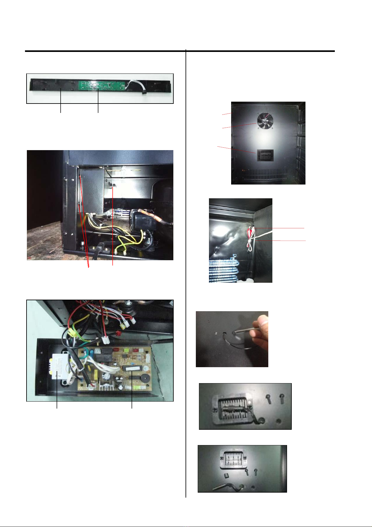
DISPLAY BOARD BOX ASSEMBLY ................................................................................................................................5-6
CONTROL BOARD & TRANSFORMER.............................................................................................................................. 6
SENSOR & FAN............................................................................................................................................................... 6-8
TROUBLESHOOTING....................................................................................................................................................... 9-12
COMPRESSOR COMPONENTS ....................................................................................................................................... 9
ANOTHER ELECTRIC COMPONENT ............................................................................................................................ …10
SERVICE DIAGNOSIS CHART.......................................................................................................................................... 11
REFRIGERATING CYCLE.................................................................................................................................................. 12
DESCRIPTION OF CONTROL PCB .....................................................................................................................................13
SAFETY PRECAUTIONS
Please read the followings beforeservicingyour appliance.
1. Check if an electric leakage occurs in the set.
2. To prevent electric shock, unplug prior to servicing.
3. In case of testing with power on, wear rubber gloves
to prevent electric shock.
4. If you use any appliances, check regular current,
voltage and capacity.
5. Don't touch metal products in cold freezer with wet
hand. It may cause frostbite.
6. Prevent water flowing to electric elements in
mechanical parts.
7. When sloping the set, remove any materials on the
set, especially thin plate type. (ex.: glass shelf or
books.)
8. When servicing evaporator part, wear cotton gloves
without fail. It is to prevent wound by sharp fin of
evaporator.
9. Leave a breakage of refrigerating cycle to a heavy
service center. The gas in cycle inside may soil
ambient air.

- 3 -
2. PARTS IDENTIFICATION
Model:RW54N1SSD
Model:RW46N1DSD

- 4 -
3. DISASSEMBLY
3-1 DOOR
Loosen 2 bolts fixing the lower right hinge to the lower
door axis to remove the door. (Figure 1)
Lower Door Axis
Lower Right Hinge
Lock Washers
BOLT Figure 1
3-2 SHELVES
(Models:RW54N1SSD)
The sides of the shelves are equipped with protective
stoppers which prevent bottles from falling from the shelves.
When removing / inserting the shelves from / into the rails,
lift one side of the shelf as shown in (Figure 2) and pull the
shelf out towards you, or push it in when inserting it, until
one side is securely seated on the rail.
Figure 2
(Model:RW46N1DSD)
To remove the shelves out of the rail, pull each shelf
approximately 1/3 out. Use a long flat screwdriver or similar
tool to press down the right plastic notch as shown in
Figure 3 and at the same time lift the left plastic notch as
shown in Figure 4. Then proceed to pull out the shelf slowly.
When inserting the shelves make sure the shelf sides fix
into the rails on both side and put to the end, and the shelf
should be move smooth, if it is not smooth, rework it
otherwise, the rails will be damaged.
Figure 3
Figure 4
3-3 LAMP
Figure 5 Figure 6
Pull the lamp cover. (figure 5)(For RW46N1DSD remove
the rail firstly)
Separate the claw fixed to the LED light. Separate the lead
wire Housing. (figure 6)
3-4 MAGNETIC SWITCHE
1. Loosen 5 screws.
2. Separate the Support bracket of front leg. (Figure 7)
Figure 7
Screw screw Screw
3. Loosen 3 screws.
4. Separate the lead wire Housing.
5. Remove the bottom gill Assy. (Figure 8)

- 5 -
3. DISASSEMBLY
Figure 8
Wire Housing screw
6. Separate the magnetic switch. (Figure 9)
Figure 9
Bottom gill magnetic switch
3-5 DISPLAY BOARD BOX ASSEMBLY
(Models:RW54N1SSD)
1. Loosen the screws. (Figure 10)
Figure 10
Screw Display board box Assy
2. Pull forward the Display board box Assy . (Figure 11)
Figure 11
3. The Display board box Assy. (Figure 12)
Figure 12
LED LIGHT Display board LED LIGHT
(Model:RW46N1DSD)
1. Separate the two screws under the Display board box Assy.
(Figure 13)
Figure 13
2. Insert a screwdriver on the left hole. (Figure 14)
Figure 14
3. Pull forward the claw and raised the Display board box
Assy a bit. (Figure 15)
Display board
box Assy
claw
Screwdriver
Figure 15
4. Repeat on the right hole. Separate the lead wire Housing.
(Figure 16)
Figure 16
left hole Wire Housing right hole
S
Screw
Figure 11

- 6 -
3. DISASSEMBLY
5. The Display board box Assy. (Figure 17)
Figure 17
Display board box Display board
3-6 CONTROL BOARD & TRANSFORMER
1. Loosen the screws. Pull out the Control board box. (Figure
18)
Figure 18
Screws Screw
2. Separate the lead wire Housing. (Figure 19)
Figure 19
Transformer Control board
3-7 SENSOR & FAN
(Models:RW54N1SSD)
1. Loosen 6 screws. Pull out the rear air duct cover. (Figure
20)
Screws
FAN
Sensor
Figure 20
2. Loosen 1 screw. (Figure 21)
Wire Housing
Screw
Figure 21
3. Press the nails with screwdriver at the back of the rear air
duct cover. (Figure 20)
Figure 22
4. Separate the sensor cover. (Figure 23)
Figure 23
5. Separate the sensor. (Figure 24)
Figure 24

- 7 -
3. DISASSEMBLY
(Model:RW46N1DSD)
1. Remove the display board box Assy according 3-5
2. Separate the top plate of middle separator. (Figure 25)
Figure 25
3. Separate the LED light lead wire Housing. (Figure 26)
Figure 26
4. Loosen 3 screws. Pull out the bottom plate of middle
separator. (Figure 27)
Screw
Figure 27
Screw
5. Loosen 6 screws. Pull out the rear air duct cover. (Figure
28)
Figure 28
6. Separate the lead wire Housings. (Figure 29)
Figure 29
7. The upper Fan, Sensor & lower Fan, Sensor. (Figure 30)
lower upper
Sensor Sensor
Fan Fan
Figure 30
Yellow wire housing Red wire housing

- 8 -
3. DISASSEMBLY
8. Press the nails with screwdriver at the back of the rear air
duct cover. (Figure 31)
Figure 31
9. Separate the sensor cover. (Figure 32)
10. Separate the sensor. (Figure 33)
Figure 33
Figure 32

- 9 -
4. TROUBLESHOOTING
1
4-1 COMPRESSOR COMPONENTS
Check the
resistance of
Motor
Compressor.
2 Check the
resistance of
PTC-Starter.
Check the resistance
among M-C(about
6Ω), S-C(about 6Ω)
and M-S(about 12Ω)
in Motor Compressor.
Check the resistance
of two terminals in
PTC-Starter.
YES
NO Replace Compressor.
YES
NO
2 3
3
Replace
PTC-Starter.
3 Check OLP.
Check if applying
a regular OLP.
NO
Replace OLP.
1
1

- 10 -
Check if current flows to
the following
components.
Cause.
a. Starting devices Shorted or broken.
b. OLP Poor contacting
or shorted.
c. Compressor coil Coil shorted.
d. Circuit Parts Poor contacting
or shorted.
4-2 ANOTHER ELECTRIC COMPONENTS
▼Cooling is impossible
Compressor
doesn't run.
Replace
each component.
Running state of
Compressor is poor. Check a starting
voltage. Low voltage. Raise the voltage.
Check if current flows
to starting devices. Poor contacting
and broken. Replace
each component.
Check current flowing
in coil of
Compressor. Shorted.
Check capacity of OLP. Lack of capacity.
The items described
above are normal. Coil of motor
Compressor. Replace
the compressor.
▼Cooling ability is poor
Fan motor
doesn't run. Check Control PCB
Check current flowing
in the Fan Motor.
Poor contacting.
Coil is shorted.
Replace
each component.
Much frost are sticked
to the EVAPORATOR. Check current flowing
of the following
components.
• Def. Sensor
• Defrost heater
Shorted. Replace
each component.
Replace
each component.

- 11 -
4-3 SERVICE DIAGNOSIS CHART
Problem
Possible Cause
Appliance does not operate.
Not plugged in.
The appliance is turned off.
The circuit breaker tripped or a blown fuse.
Appliance is not cold enough.
Check the temperature control setting. External
environment may require a higher
setting.
The door is opened too often.
The door is not closed completely.
The door gasket does not seal properly.
NO cooling enough
The room temperature is hotter than normal.
A large amount of contents has been added to the wine chiller.
The door is opened too often.
The door is not closed completely.
The temperature control is not set correctly. The door
gasket does not seal properly.
The light does not work.
Not plugged in.
The circuit breaker tripped or a blown fuse. The bulb has
burned out.
The light button is “OFF”. Energy conservation button is on.
button is on.
Vibrations.
Check to assure that the Wine Chiller is level.
The Wine Chiller seems to make too much noise.
The rattling noise may come from the flow of the refrigerant,
which is normal.
As each cycle ends, you may hear gurgling
sounds caused by the flow of refrigerant in your
Wine Chiller.
Contraction and expansion of the inside walls may cause
popping and crackling noises.
The Wine Chiller is not level.
The door will not close properly.
The Wine Chiller is not level.
The door was reversed and not properly installed. The gasket is
dirty.
The shelves are out of position.
Display error code “E3”or “E4”.
(Models:RW54N1SSD):The defrost sensor is failed.
Display error code “E7”or “E8”.
(Models:RW46N1DSD):The lower zone sensor is failed.
Display error code “E0”or “E1”.
(Models:RW54N1SSD):The inner sensor is failed.
(Models:RW46N1DSD):The upper zone sensor is failed.

- 12 -
4-4 REFRIGERATING CYCLE
▼Troubleshooting Chart
CAUSE
STATE OF
THE SET
STATE OF THE
EVAPORATOR
TEMPERATURE
OF THE
COMPRESSOR
REMARKS
LEAKAGE
PARTIAL
LEAKAGE
Appliance
don't get cold
normally.
Low flowing sound of
Refrigerant is heard and
frost forms in inlet only
A little high
more than
ambient
temperature.
• A little Refrigerant
discharges.
• Normal cooling is possible
when injecting Refrigerant
of regular amount.
WHOLE
LEAKAGE
Appliance
don't get cold
at all.
Flowing sound of Refrigerant
is not heard and frost isn't
formed.
Equal to ambient
temperature.
• No discharging of Refrigerant.
• Normal cooling is possible
when injecting Refrigerant
of regular amount.
CLOG
PARTIAL
CLOG
Appliance
don't get cold
normally.
Flowing sound of Refrigerant
is heard and frost forms
in inlet only.
A little high
more than
ambient
temperature.
• No discharging of
refrigerant.
• The capillary tube is faulty.
WHOLE
CLOG
Appliance
don't get cold.
Flowing sound of Refrigerant
is not heard and frost isn't
formed.
Equal to ambient
temperature.
• No discharging of
Refrigerant.
▼Leakage Detection
Observe discharging point of refrigerant which may be in oil discharging part in compressor and hole of evaporator.
Whether Compressor
runs or not.
YES Whether frost
forms or not in
Evaporator.
No frost or forms
in inlet only
Whether oil leaks
or not.
Faulty
Normal amount
Inject Refrigerant to
Observe the discharging
amount of Refrigerant.
No or much amount
YES
Compressor. Compressor and check
cooling operation.
Check Compressor Clogged by dust. Gas leakage.
Normal formed
frost in Evaporator (Check the leakage point)

- 13 -
5.
DESCRIPTION
OF CONTROL PCB
(Models:RW54N1SSD) (Figure 34)
Figure 34
(Model:RW46N1DSD) (Figure 35)
Figure 35
Other manuals for RW54N1SSD
1
This manual suits for next models
1
Table of contents
Other Hisense Kitchen Appliance manuals