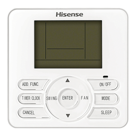
Hisense YJE-C01T Technical manual

Thank you very much for purchasing this Air Conditioner. Please
read this carefully before installing use and installation instructions
and using this appliance.And keep this manual for future reference.

YJE-C01T(E)
Welcome to use our product!
Thanks for trusting us.
Please read this manual carefully before installation!
Keep it properly for future use after installation!
APPLICATION MODEL
确定
ZONE
CONTENTS
fety Precautions ----------------------------------------------------------------1Sa
1.Important notice -------------------------------------------1
2.Checking product ------------------------------------------1
3.Safety summary -------------------------------------------2
System Introduction--------------------------------------------------------------3
Central Controller Introduction(Part name)-------------------4
Introduction to Parts of Central Controller ------------------------4
Liquid Crystal Display Screen ----------------------------------6
Central Control---------------------------------------------------------------------7
Simple Operation------------------------------------------------------------------9
Function Set------------------------------------------------------------------------1 1
Cl oc k- -- -- -- -- -- -- -- -- -- -- -- -- -- -- ------------------11
Button Locked -----------------------------------------------11
Simple TIMER ON --------------------------------------------12
Simple TIMER OFF--------------------------------------------13
Weekly Timer -----------------------------------------------14
Other Functions------------------------------------------------------------------16
TEMP. Display Setting ---------------------------------------16
Buzzer Indicator Selection --------------------------------------16
Backlight Selection-------------------------------------16
Maintenance, Troubleshooting and After-Sales Service---------------17
Installation Instructions----------------------------------------------------------18

Safety Precautions
1. Important notice
2. Checking product
● We pursue a policy of continuing improvement in design and performance
of products. The right is therefore reserved to vary specifications without notice.
● We cannot anticipate every possible circumstance that might involve a
potential hazard.
● No part of this manual can be reproduced without written permission.
● Signal words (DANGER, WARNING and CAUTION) are used to identify
levels of hazard seriousness. Definitions for identifying hazard levels are provided
below with their respective signal words.
Useful information for operation and/or maintenance.
●Upon receiving this product, inspect it for any shipping damage .
Claims for damage, either apparent or concealed, should be filed immediately with the
shipping company.
●Check accessories are all included with the unit according to the accessories list.
●Check the model number,electrical characteristics (power supply ,voltage and
frequency) and accessories to determine if they are correct.
The standard utilization of the unit shall be explained in this manual.
Therefore, the utilization of the unit other than those indicated in this manual is not
recommended.
●Follow local codes and regulations when installing it.
Please contact your local agent, as the occasion arises.●
!
!
!
●If you have any questions, contact your distributor or dealer .
● This manual should be considered as a permanent part of the air conditioning equipment
and should remain with the air conditioning equipment.
Immediate hazards which WILL result in severe
personal injury or death.
Hazards or unsafe practices which COULD result in severe
personal injury or death.
Hazards or unsafe practices which COULD result in minor
personal injury or product or property damage.
:
:
:
1
Our company disclaim all responsibility for changing the equipment without our
company's written consent.
●Installation and maintenance should be left to dealer or another professional.
:

●Installation should be left to the dealer or another professional person.
Improper installation may cause water leakage, electrical shock, or fire..
●Perform the installation correctly referring to the installation manual.
Incorrect installation could cause a personal injury due to fire, electric shock.
●Do not splash water on the appliance and do not touch it with wet hand .
These products are equipped with electrical components , splashing water could cause serious
electric shock or short-circuit.
●Must not touch or regulate safety device in the appliance.Otherwise serious accident may occur.
●Please be sure to cut off the main power supply before opening the panel to repair.
●Please use specify specifications cable.Firmly connected to the connection part of wire terminals ,
and avoid being shell. Do not apply wire stress to these parts. Otherwise it will cause fever or
fire,etc.
●Install the appliance on the base that can support its weight. Otherwise it may cause injury in the event
the appliance falls off the base.
●Connect with the electric supply after installation and check electric leakage.
●Avoid the following places for installation where appliance trouble is liable to occur.
·Places with an oily or or ambient.acidic, alkaline
·Places where sulfide gas occurs such as hot springs.
·Places with a flammable gas.
·Salty places such as seaside .
·Places with high temperature or flames,may lead to heat or fire.
·Where there is high-frequency or wireless equipment. It will cause interference .
Moisture or water flooding place. Once the water enters the inside of the remote control,
electric shock or electronic parts failure may occur.
●Do not install the appliance or connect the wires before reading the manual.
3. Safety summary
2
!
!
●Prohibit within the scope of 1 meter of the appliance using spray,such as pesticides,
paint, hair gel or other toxic gases.
●If the ELB(Electric Leakage Break) or fuse trouble is liable to occur,please consult local service shop.
●Installation and wring work should be perform according to the manual.
Otherwise electric shock or fire may occur.
●Do not ride or place the object that with no relation with the appliance on the unit.
●Protect the wires, electrical parts, etc. from rats or other small animals. If not protected, rats may gnaw
at unprotected parts and at the worst, a fire will occur.
●Firmly connect wires. Excessive force may cause fire.
●If the electric box or fuse break is liable to occur, please consult local service shop.
●Install indoor unit,outdoor unit ,wire remote controller or cables at least 3 meters away from high-
frequency source (such as medical appliance) .
● Do not trample products or place anything on it.
●Choose a place as described below to install wire remote controller in order to let TEM. sensor work normally.
A.A place where average temperature in the room can be detected.
B.A place where is not exposed to direct sunlight.
C.Avoid extremely hot or cold locations.
●Do not play with the wire remote controller.
!
Safety Precautions
Indoor unit
B-
B- B-
B-
B- B-
B- B- B- B-
A+
A+ A+
A+
A+ A+
A+ A+ A+ A+
RS485 shielded twisted pairs
(with polarity, A+ B-)
Rs485 shielded twisted pairs
(with polarity, A+ B-)
Indoor unit
Wired
controller
Wired
controller
Indoor unit
Wired
controller
220V ~/50Hz Indoor unit
N
GND
L
Wired
controller
··· ···
··· ···
RS485 shielded twisted pairs
(with polarity, A+ B-)
RS485 shielded twisted pairs
(with polarity, A+ B-)
Central box Central box Central box Central box
Indoor unit
Indoor unit
Indoor unit Indoor unit 220V ~/50Hz
N
GND
L
··· ···
··· ···
The central controller is an optional control component for users to monitor and control
operation of air conditioner in a centralized way.
The central controller can be used for unified management of the air conditioners in the
group/zone, querying and displaying on LCD the state of the main functions of the air
conditioner, weekly timer/simple timer setting or querying by keypad entry or setting of
main functions of air conditioner.
Communicate with the indoor unit in the central control network
It can communicate with the wired controller/indoor unit through RS485 communication
bus (shielded twisted pairs with polarity (A+ B-)). The indoor unit can be controlled centrally
or locally by using the wired controller, or centrally controlled by using converter (to be
purchased by users separately).
System Introduction
Control Diagram
1. Centrally or locally controlling the air conditioner using wired controller
2. Centrally controlling the air conditioner using converter board
3
Central controller
communication line
Central controller
communication line
Central controller
communication line
Central controller
communication line
Indoor unit
connection line
Central box
connection line
Central controller
power line
Central controller
power line
Notes:
1. The central box needs to be purchased by users separately.
2. The wired controller/central box on either end of the central
control system must be provided with terminal-matched resistor.
See the installation instructions for the wired controller/central box
for more details.

Introduction to Parts of Central Controller
4
Central Controller Introduction(Part Name)
2
10
13
11
12
1
3
4
7
8
9
5
6
ZONE

ON/OFF BUTTON
The appliance will be started when you press this button and be stopped
when you press this button again.
RUN INDICATOR
Indicates that the appliance is on.
MODE BUTTON
Press this button to select the operation mode.
FAN BUTTON
Used to select desired fan speed in sequence low-medium-high-auto-low.
SWING BUTTON (invalid for models without louver)
Used to stop or start adjustment louver swinging and set the desired airflow
direction.
TIMER/CLOCK BUTTON
Used to set timer on/off and clock time.
ZONE BUTTON
Used to set the group/zone.
ENTER BUTTON
Used to confirm settings.
CANCEL BUTTON
Used to cancel settings.
ADD.FUNC. BUTTON(Only valid for models with addition function module)
Used to set functions of air purge, hot water, ventilation (fresh air), and
electric heater.
INCREASE SETTING BUTTON
Used to raise the set temperature.Settings can be raised in a setting state.
DECREASE SETTING BUTTON
Used to lower the set temperature;Settings can be lowered in a setting state.
LIQUID CRYSTAL DISPLAY (LCD) SCREEN
Used to display the icons of set functions.
1
1
2
3
4
5
6
7
8
9
10
11
12
13
5
Central Controller Introduction(Part Name)

LCD Screen
Notes:
1. Heating and electric heating functions are not available for cooling only models.
2. Air direction, filter clean, hot water, floor heater, ventilation (fresh air), air purge, and electric
heating functions are only effective for dedicated models, please refer to the operation manual
of specific model for details.
3. Error and maintenance, address setting, and zone setting functions should be set by the
professional for installation and maintenance.
6
Cooling Mode
Group Indicator
Relative Moisture
Zone/Unit Indicator
Locked Indicator
Fahrenheit Temperature
Hot Water
Electric Heater
Ventilation
Sleep Mode
Group/Zone No.
Error Indicator
Clock
Fan Speed
Left/Right Air Direction Indicator
Up/Down Air Direction Indicator
Day of Week
Week Indicator
Centigrade Temperature
Air Purge
Filter Clean
Dry Mode
Fan-only Mode
Heating Mode
Timer Indicator
Holiday Indicator
Date
Timer ON Indicator
Timer OFF Indicator
Daylight Saving Time Indicator
Floor Heater
Fan
Hot Water TEMP.
Room TEMP.
Central Controller Introduction(Part Name)

ADD. FU NC.
TIMER /CL OCK
CANCE L
SWING
FAN
ENTER
ON/OF F
MODE
ZONE
Before central control, group/zone settings must be carried out.
Group setting
If the centralized controller at the next higher level is used,
group setting needs to be carried out. The group number is
only effective for the centralized controller.
All conditioners in the central control network can be
classified into a range of group 1 to group 16.
Setting method:
Hold down “ADD. FUNC.” Button under shutdown state for 3
seconds to enter into group setting, and “GROUP” indicator
and group number blink. Press “ ” or “ '' to select the
group number. Press “ENTER” button to confirm the set
group number, press “CANCEL” button to cancel.
Zone setting
In a central control network, a maximum of 16 zones can be
set. The same unit can be classified into different zones. A
maximum of 16 air conditioners can be set in one zone.
1. Hold down “ZONE” button for 3 seconds to enter into zone
setting, and the zone number blinks. Press “ ” or “ '' to
select the zone number. Press “ENTER” button to enter into
setting of this zone.
2. Press “ ” or “ '' to select the air conditioner address
numbers from 1 to 16, and the number blinks. Press
“ENTER” button to confirm the selected number which is
underlined. Press “CANCEL” button to cancel.
3. Press “ZONE” button to enter into setting of the next zone.
A maximum of 16 zones can be set.
4. Press “ZONE” button again to exit the zone setting.
Group indicator
Group
number
ADD. FU NC.
TIMER /CL OCK
CANCE L
SWING
FAN
ENTER
ON/OF F
MODE
ZONE
1
2
3
3
Zone
number
Air conditioner
address
Zone selection
Unit selection
Setting completed
7
1. Group Control Mode (for the control of all conditioners in the central control network)
To control the air conditioners in the group in a unified manner.
2. Zone Control Mode
To control the air conditioners in the zone in a unified manner.
Central Control
Operation Modes of Central Controller

Group control (full control)
1. After entering the group control mode, you can perform as
follows:
Press “ZONE” button repeatedly until the group number and
addresses of all air conditioners in the group are displayed
on the central controller.
As shown in the right figure, the group number is 1, and there
are 16 air conditioners in this group.
2. Unified function setting can be performed by other buttons
(for detail description, please refer to instructions for specific
operation procedure).
Sub-zone control
1. After entering the sub-zone control mode, you can perform
as follows:
Press “ZONE” button repeatedly until the number of the zone
to be controlled and addresses of all air conditioners in the
zone are displayed.
As shown in the right figure, the zone number is 1, and there
are No.1, 2, and 3 air conditioners in this zone.
2. Function setting can be performed by other buttons (for
detail description, please refer to instructions for specific
operation procedure).
Special notes:
1. If no zone is set, only the group number will be displayed.
2. In the zone control mode, you can press “CANCEL” button
to enter the group control mode.
Monitoring
After the central controller is started, the LCD on the central
controller displays the operating state of the air conditioners
in the network in turn if no other operation is carried out.
Full unified control
Sub-zone control
8
Central Control

This central controller is used for unified cooling, heating, drying and air supply, etc. of
the air-conditioners in the group/zone. For other functions and settings, please refer to the
details on the setting of functions in this manual.
1. Turning ON/OFF
To start operation
When pressing the ON/OFF button in off state,
the ON indicator lights up and the starting
command will be sent to air conditioners in the
group/zone.
To stop operation
When pressing the ON/OFF button in on state, the
ON indicator turns off and the shutdown command
will be sent to air conditioner in the group/zone.
At this time, the set weekly timer ON (if any) will
take effect.
To completely shut down
Hold down "ON/OFF" button for more than 3
seconds, the central controller will enter completely
shutdown state (at this moment, the timer ON is
disabled and the appliance only can be started
manually), the ON indicator turns off, and shutdown
command will be sent to air conditioners in the
group/zone.
2. Mode setting
Press“MODE” button to select the desired operation mode in ON state, or OFF state with timer set.
Once the MODE button is pressed, the operation mode is changed in sequence:
3. Temperature setting
Press “ ”or “ ”button to set desired temperature in ON state, or in OFF state with timer set.
Then the temperature setting will blink on the LCD, indicating entering setting mode.
Each time “ ” button is pressed, temperature setting rises by 1C.
Each time “ ”button is pressed, temperature setting lowers by 1C.
Setting temperature is finished 3 seconds after setting temperature value blinking.
16℃30 18 ~32℃/ ℃ ℃
Range of temperature setting
*Cooling, heating, drying
Fan only Unable to be set
1. The ON/OFF button of central controller is only used to change the ON/OFF state of the air
conditioners in the group/zone without affecting the other settings.
2. When the wired controller (if any) for the group/zone receives the shutdown command from
the central controller, the appliance will enter completely shutdown state.
~
9
操
作
方
法
*: Note: Heating mode is unavailable for COOLING ONLY models.
Simple Operation
COOLING HEATING
FAN ONLY
DRY
确定
1
2
4
5
3
3
ZONE

5. SWING setting
Press “SWING” button to select SWING in ON state, or in OFF state with timer set. Each time “SWING”
button is pressed, the SWING changes in the following sequence.
1. This setting is only effective for units with this swing function.
2. is only available for specific models.
3. At “DRY” mode, the fan speed is set at “AUTO” automatically and “FAN” button is ineffective
in this case.
Nothing
No display
LOW MEDIUM HIGH AUTO (display lights on in turn
as indicated by the arrow)
4. Fan speed setting
Press “SPEED” button to select fan speed in ON state, or in OFF state with timer set. Each time “SPEED”
button is pressed, the fan speed changes in the following sequence:
10
Up/Down SWING Left/Right SWING Up/Down/
Left/Right SWING
Simple Operation

Button Locked
After central controller setting is finished, you can set
button locked function to avoid children or other
people's wrong operation.
All operations are invalid after button locked function has
been set. After locking, the central controller still can
operate normally. And unlocking can only be performed
by the central controller.
How to set:
Hold down “ENTER” button for 3 seconds, the buzzer beeps 4 times indicating the setting is successfully set
and is displayed on the LCD, indicating that the wired controller is now under the button locked state.
How to cancel:
Hold down “ENTER” button for 3 seconds, the buzzer beeps 4 times indicating the setting is canceled
and disappears from the LCD, indicating that the button locked function has been canceled.
11
Button Locked
First time using and clock loss caused by unused for a long
time, setting clock of central controller is needed at first.
How to set:
1 Indicators of date and day of week all blinks after turning
on.
2 Press “ ”and “ ” to set the current date, day of week,
hour, minute in sequence. Press “ENTER” to confirm.
Clock Correction
Hold down“TIMER/CLOCK” button for 3 seconds under
complete shutoff state to enter clock correct setting.
The settings of clock can be adjusted in the following sequence
and the same method as clock setting.
After the adjustment is completed, press “ENTER” button
to confirm the setting.
After the clock has been set, the central controller will display
the current clock.
Year Month, Day days of week hour, minute
Indicator of
day of week
ClockDate
Clock
1. Clock correction should be set under complete shutoff state.
2. If there are two central controllers in the system, only the clock set on the main central controller is effective.
3. Complete shutoff: When turning on, hold down “ON/OFF” button for 3 seconds will enter complete shutoff
state.
Temporary shutoff: When turning on, press “ON/OFF” button will turn to temporary shutoff state.
Shutoff state in this manual all means temporary shutoff.
Function Set
ADD. FUNC.
TIMER/CLOCK
CANCEL
SWING
FAN
ENTER
ON/OFF
MODE
ZONE
ADD. FUNC.
TIMER/CLOCK
CANCEL
SWING
FAN
ENTER
ON/OFF
MODE
ZONE
1
3
2
2

Operation:
1 After you press TIMER/CLOCK button when the
appliance is shut off, and timer on indicator “ON”
display on LCD, and timer hour setting blinks.
2 Press “ ” (increase) and “ ” (decrease) button to adjust
the time.
Each time “ ” button is pressed, time setting increases
by 1h.
Each time“ ” button is pressed, time setting decreases
by 1h.
It can be set from 1h to 24h, and time setting resolution is
1 hour.
3 Press “ENTER” button when reaches the desired time .
After operation, the display will be back to previous display
before timer on set, and “Timer” indicator appears on the
left corner of the screen.
You can press the “CANCEL” button at any time to cancel
the timer on setting and exit.
You can press the “TIMER/CLOCK” button to cancel the
current setting and exit.
Press “TIMER/CLOCK” button again after TIMER ON has
been set to display the rest of the time.
As shown in the figure, it indicates that the appliance will
be started after 58 minutes.
After the set time is reached, the air conditioners in the
current group/zone will be turned on under unified control.
12
1. Simple timer on function only can be set under shutoff mode.
2. After time setting of TIMER ON FUNCTION, you can set/change mode, adjust temperature
and fan speed, and set swing mode (if any).
3. After the appliance is turned on, simple timer on function will be cancelled. If you need simple
timer setting effective continuously, please set weekly timer.
4. Simple timer on/off cannot be set simultaneously.
5. Simple timer on setting is only effective for the current group/zone.
Time setting of TIMER ON FUNCTION
Display of TIMER ON mode
Rest time of TIMER ON Mode
Simple TIMER ON (invalid under weekly timer set)
ADD. FUNC.
TIMER/CLOCK
CANCEL
SWING
FAN
ENTER
ON/OFF
MODE
ZONE
1
2
Function Set

Operation:
1 After you press TIMER/CLOCK button when the
appliance is on, and timer off indicator “OFF” display
on LCD, and timer hour setting blinks.
2 Press “ ” (increase) and “ ” (decrease) button to adjust
the time.
Each time “ ” button is pressed, time setting increases
by 1h.
Each time“ ” button is pressed, time setting decreases
by 1h.
It can be set from 1h to 24h, and time setting resolution
is 1 hour.
3 Press “ENTER” button when reaches the desired time .
After operation, the display will be back to previous display
before timer off set, and “Timer” indicator appears on the
left corner of the screen.
You can press the "CANCEL" button at any time to cancel
the timer off setting and exit.
You can press the “TIMER/CLOCK” button to cancel the
current setting and exit.
Press “TIMER/CLOCK” button again after TIMER OFF has
been set to display the rest of the time.
After the set time is reached, the air conditioners in the
current group/zone will be turned off under unified control.
13
功
能
设
定
Time setting of TIMER OFF FUNCTION
Display of TIMER OFF mode
Rest time of TIMER OFF Mode
Simple TIMER OFF (invalid under weekly timer set)
1. Simple timer off function only can be set in on state.
2. After time setting of TIMER OFF FUNCTION, you can set/change mode, adjust temperature and fan speed,
and set swing mode (if any).
3. After the appliance is off, simple timer off function will be cancelled. If you need simple timer setting effective
continuously, please set weekly timer.
4. Simple timer on/off cannot be set simultaneously.
5. Simple timer off setting is only effective for the current group/zone.
ADD. FUNC.
TIMER/CLOCK
CANCEL
SWING
FAN
ENTER
ON/OFF
MODE
ZONE
1
2
Function Set

ADD. FUNC.
TIMER/CLOCK
CANCEL
SWING
FAN
ENTER
ON/OFF
MODE
ZONE
Weekly timer can be used to set on/off time respectively for seven days a week. Air conditioner
can be on/off in preset time every day, without manual control. The air conditioner can be on/off
automatically before you wake up in the morning, back home from work or during sleep at night.
Weekly timer on/off time can be set for four groups at most. The four groups can be assigned to
any day regularly.
Note: Please set the clock correctly before weekly timer set.
功
能
设
定
14
Weekly Timer
Weekly Timer Set Procedure
Operation Procedure
OPERATION:
1 Hold down “TIMER/CLOCK” button for 3 seconds to enter
weekly timer setting in ON/OFF state. Then appears on the
LCD, and group number blinks.
Perform further settings in the following sequence:
First timer group number 1 blinks. Then press “ENTER” button to enter Timer ON setting.
2
3
4
GROUP SELECT
GROUP SELECT
GROUP SELECT
GROUP SELECT
QUIT
NOTE:
START
Press“TIMER/CLOCK”button or“ON/OFF”button
Hold on“TIMER/CLOCK”button for 3 seconds
PRESS“TIMER/CLOCK”BUTTON
OR
OR
OR
OR
(Turning ON/OFF)
DAY SELECT
DAY SELECT
DAY SELECT
DAY SELECT
Press the "ENTER" button to the next step
Press or button to select the next group
TIMER ON HOUR
TIMER ON HOUR
TIMER ON HOUR
TIMER ON HOUR
TIMER ON MINUTE
TIMER ON MINUTE
TIMER ON MINUTE
TIMER ON MINUTE
TIMER OFF HOUR
TIMER OFF HOUR
TIMER OFF HOUR
TIMER OFF HOUR
TIMER OFF MINUTE
TIMER OFF MINUTE
TIMER OFF MINUTE
TIMER OFF MINUTE
GROUP SELECT
DAY SELECT
TIMER ON HOUR
TIMER ON MINUTE
TIMER OFF HOUR
TIMER OFF MINUTE
Function Set

If you need to temporarily leave for a few days when weekly timer has been set, at the
meanwhile timer ON/OFF is not permitted to work and continue to work after back, you
can hold down “ON/OFF” button for 3 seconds to turn it off completely. At this moment,
weekly timer set time can still save, but air conditioner will not run.
Weekly timer setting resolution is 1 minute. Timer ON/OFF signal is effective within 1 minute.
15
2 Timer on hour blinks. Then press “ ” (increase) or “ ''
(decrease) button to set the desired time.
Each time “ ” button is pressed, time increases by 1h.
Each time “ ” button is pressed, time decreases by 1h.
After timer ON hour has been set, press “ENTER” button
to return to timer ON minute setting.
If you don't need timer ON/OFF Setting, press the "CANCEL"
button to cancel.
3 Timer OFF setting can be performed in the same procedure
with timer ON setting.
4 After TIMER ON/OFF setting is completed, press “ ”
(increase) or “ ''(decrease) to select desired day, press
“ENTER” button to confirm it, or press “CANCEL” button to
cancel. The selected day will be marked with “.”.
For example, shows 7 days of a week all
selected are effective.
5 After the setting of seven days a week is completed,
proceed to the setting for group 2, which can be performed
in the same setting procedure as group l. Four groups can
be set at most.
6 You can quit WEEKLY TIMER setting by pressing
“TIMER/CLOCK” or “ON/OFF” button in the group
selection mode.
Checking the current weekly timer setting
Press “TIMER/CLOCK” button to check WEEKLY TIMER
setting in this mode.
Press “ ” (increase) or “ '' (decrease) button to check the
previous or next set time.
You can press “TIMER/CLOCK” button under checking state
to quit checking of WEEKLY TIMER.
Timer Group Select
Timer ON Setting
Timer OFF Setting
Timer Day Select
Function Set

部
件
介
绍
ADD. FUNC.
TIMER/CLOCK
CANCEL
SWING
FAN
ENTER
ON/OFF
MODE
ZONE
部
件
介
绍
ADD. FUNC.
TIMER/CLOCK
CANCEL
SWING
FAN
ENTER
ON/OFF
MODE
ZONE
部
件
介
绍
ADD. FUNC.
TIMER/CLOCK
CANCEL
SWING
FAN
ENTER
ON/OFF
MODE
ZONE
Default display: set temperature
If you need to display room temperature, press “ ” button and
“ENTER” button simultaneously for 3 seconds. Then the buzzer
beeps 4 times indicating setting has been changed. Then appears
on the LCD, indicating that the temperature shown on LCD is room
temperature.
If you need to cancel setting, press “ ” button and “ENTER” button
simultaneously for 3 seconds. Then disappears on the LCD,
indicating that the temperature shown on LCD is the set
temperature.
The buzzer beeps during operation by default. If you need mute
operation, hold down “FAN” button for 3 seconds, and the
buzzer beeps 4 times indicating setting has been successfully
changed.
If you need to return to defaulted setting, repeat steps above.
The backlight of the screen lights up during operation by default.
If you need to turn off the backlight, hold down “MODE” button
for 3 seconds and the buzzer beeps 4 times indicating setting
has been successfully changed.
If you need to return to defaulted setting, repeat steps above.
16
Temperature Display Setting
Buzzer Indicator Selection
Backlight Selection
Other Functions

Maintenance
Maintenance, Troubleshooting and After-Sales Service
Wipe the LCD of central controller and body of the wired controller with a dry cloth when they
become dirty.
If the dirt on the surface cannot be removed, soak the cloth in neutral detergent diluted with
water, squeeze the cloth tightly, and clean the surface. Wipe the surface with a dry cloth then.
Do not use any thinner, organic solvents, or strong acid.
17
Troubleshooting and After-sales Service
When the air conditioner malfunctions, will display on the LCD of wired controller, and
error codes will appear, indicating that error occurs.
Please take note of the indicated error codes to contact with the After-sales Service.
故
障
与
维
修
●Consult the dealer for more information about the after-sales service.
Error code

Important Notice
Please read the Important Notice in these Installation Instructions supplied with the central
controller, and perform installation in accordance with these instructions properly.
18
Installation Instructions
1. Complete information for the design planning, installation, commissioning, and after-sales
services of the central control system must be documented and archived for future reference.
2. Design planning of the central control system should be planned in advance, including:
(1) Composition of the central control system and quantity of controls;
(2) Selection and installation position of wired controller, electrical distribution and wiring,
assignment of addresses, and connection with controller;
(3) Installation position of central controller, setting of primary and secondary central
controllers, electrical distribution and wiring, and connection with wired controller;
(4) Installation and wiring of the central control system, limitation on bus length, terminal-
matched resistor at either end of bus, single-point grounding of the shielding layer of bus.
3. Notes:
(1) Cables for central control and distribution lines shall not be too close to each other or
routed in the same conduit. RS485 bus should be arranged as far away from interference
sources as possible, especially high voltage interference sources, such as transformer and
frequency converter. For other relevant precautions, see the requirements for wiring of
building automation system;
(2) The total length of the central control bus should not be more than 1000m (at the baud rate
of 9600 bps);
(3) The appliance on either end of the central control bus must be provided with terminal-
matched resistor. See the dip switch setting instructions for central controller/wired
controller/central box;
(4) It is recommended that single-point grounding of the shielded cable shall be arranged in
the middle of communication bus and close to the central controller;
(5) Central control line topology should be daisy-chain bus arrangement. If star topology or
tree topology is required, it is recommended that 485 concentrators and 485 repeaters be
used.
4. The wiring and installation of the central control network should be performed along with the
installation and commissioning of air conditioner. Test run should be performed before
installation.
5.The primary and secondary controllers can be set to operate at the same time in one central
control system with at least one controller as the primary central controller.
Check and confirm that in addition to the wired controller, the following accessories are
included in the packaging box:
Select the installation location according to the Importance Notice in the Instructions.
1. Selecting the location where the central controller is to be installed.
Qty.: 1 Qty.: 2
Use and installation instructions Screw
Checking Accessories
How to install
This manual suits for next models
1
Table of contents
Other Hisense Remote Control manuals

Hisense
Hisense Y-H1 User manual

Hisense
Hisense L1-04 User manual

Hisense
Hisense BR0013 User manual

Hisense
Hisense BRCB0006 User manual

Hisense
Hisense 32K26 Operating manual

Hisense
Hisense HYE-W01 User manual

Hisense
Hisense GoClick HT005E User manual

Hisense
Hisense ERF2A60 User manual

Hisense
Hisense J1-91 User manual

Hisense
Hisense W9HBRCB0005 User manual