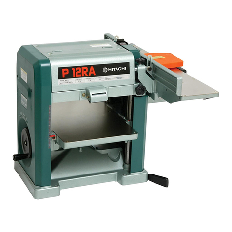
Hitachi P 12RA User manual

©
HITACHI
PORTABLE
PLANER
JOINTER
MODEL
312mm
(12
9/32")
P12RA
INSTRUCTION
MANUAL
Important
:
For
your
own
safety,
read
this
INSTRUCTION
MANUAL
before
operating
the
power
tool.
Keep
this
MANUAL
available
as
an
important
reference
when
using
the
Power
Tool.
El
DOUBLE
INSULATION

IMPORTANT
INFORMATION
Most
accidents
of
power
tool
operation
and
maintenance
are
caused
by
failure
to
observe
basic
safety
rules
or
precautions.
An
accident
can
often
be
avoided
by
recognizing
potentially
hazardous
situations
before
it
occurs.
Read
and
understand
all
safety
precautions
and
warnings
before
operation
and
maintenance.
Basic
safety
precautions
are
outlined
in
the
"SAFETY
section
of
this
manual
and
in
descriptions
of
operation
and
maintenance.
Operations
that
may
cause
bodily
injury
or
machine
damage
are
identified
by
CAUTION
signs
on
the
machine
and
in
this
manual.
Hitachi
cannot
anticipate
every
possible
circumstance
that
might
involve
a
potential
hazard.
The
CAUTIONS
in
this
manual
and
on
the
machine
are
therefore
not
all
inclusive.
Ға
procedure,
too!
or
work
method
or
operating
technique
not
specifically
recommended
by
Hitachi
is
used,
you
must
satisfy
yourself
that
it
is
safe
for
you
and
others.

SAFETY
SAFETY
RULES
FOR
POWER
TOOLS.
Ж
WARNING
:
When
using
electric
tools,
basic
safety
precautions
should
always
be
followed
—
e
оо
СЛ
10.
11.
12.
13.
14.
15.
16.
17.
to
reduce
the
risk
of
fire,
electric
shock,
and
personal
injury,
including
the
following.
READ
ALL
INSTRUCTIONS
.
KEEP
GUARDS
IN
PLACE
and
in
working
order.
.
REMOVE
ADJUSTING
KEYS
AND
WRENCHES.
Form
а
habit
of
checking
to
see
that
keys
and
adjusting
wrenches
are
removed
from
tool
before
turning
it
on.
.
KEEP
WORK
AREA
CLEAN.
Cluttered
areas
and
benches
invite
accidents.
.
DON
T
USE
IN
DANGEROUS
ENVIRONMENT.
Don’t
use
power
tools
in
damp
or
wet
locations,
or
don’t
expose
them
to
rain.
Keep
work
area
well
lighted.
.
KEEP
CHILDREN
AWAY.
All
visitors
should
be
kept
safe
distance
from
work
area.
.
MAKE
WORKSHOP
KID
PROOF
with
padlocks,
master
switches,
or
by
removing
starter
keys.
.
DONT
FORCE
TOOL.
It
will
do
the
job
better
and
safer
at
the
rate
for
which
it
was
designed.
.
USE
RIGHT
TOOL.
Don’t
force
tool
or
attachment
to
do
a
job
for
which
it
was
пої
designed.
.
WEAR
PROPER
APPAREL.
Wear
no
loose
clothing,
gloves,
neckties,
rings,
bracelets,
or
other
jewelry
which
may
get
caught
in
moving
parts.
Nonslip
footwear
is
recommended.
Wear
protective
hair
covering
to
contain
long
hair.
ALWAYS
USE
SAFETY
GLASSES.
Also
use
face
or
dust
mask
if
cutting
operation
is
dusty.
Everyday
eyeglasses
only
have
impact
resistant
lenses,
they
are
NOT
safety
glasses.
SECURE
WORK.
Use
clamp
or
a
vise
to
hold
work
when
practical.
It’s
safer
than
using
your
hand
and
it
frees
both
hands
to
operate
tool.
DON'T
OVERREACH.
Keep
proper
footing
and
balance
at
all
times.
MAINTAIN
TOOLS
WITH
CARE.
Keep
tools
sharp
and
clean
for
best
and
safest
performance.
Follow
instructions
for
lubricating
and
changing
accessories.
DISCONNECT
TOOLS
before
servicing
;
when
changing
accessories
such
as
blades,
etc..
REDUCE
THE
RISK
OF
UNINTENTIONAL
STARTING.
Make
sure
switch
is
in
off
position
before
plugging
in.
USE
RECOMMENDED
ACCESSORIES.
Consult
the
owners
manual
for
recommended
accessories.
The
use
of
improper
accessories
may
cause
risk
of
injury
to
persons.
NEVER
STAND
ON
TOOL.
Serious
injury
could
occur
if
the
tool
is
tipped
or
if
the
cutting
tool
is
unintentionally
contacted.

18.
19.
20.
21.
22.
CHECK
DAMAGED
PARTS.
Before
further
use
of
the
tool,
а
guard
or
other
part
that
ts
damaged
should
be
carefully
checked
to
determine
that
it
will
operate
properly
and
perform
its
intended
function-check
for
alignment
of
moving
parts,
binding
of
moving
parts,
breakage
of
parts,
mounting,
and
any
other
conditions
that
may
affect
its
operation.
A
guard
should
be
properly
repaired
or
replaced.
DIRECTION
OF
FEED.
Feed
work
into
a
blade
or
cutter
against
the
direction
of
rotation
of
the
blade
only.
NEVER
LEAVE
TOOL
RUNNING
UNATTENDED.
TURN
POWER
OFF.
Don't
leave
tool
until
it
comes
to
a
complete
stop.
When
servicing
use
only
identical
replacement
parts.
Apply
АС
115
voits
only.
Applying
fluctuated
AC
115
voijts
or
applying
DC
power
could
cause
the
POWER
TOOL
to
mis-operate
and
thus
cause
serious
injury
or
damage.

Specific
Safety
Rules
for
Power
Tool
These
specific
safety
rules
of
"DO’s”
and
“DON'Ts”
apply
to
this
POWER
TOOL.
бо
N
СО
чо
л
+
14.
15.
16.
17.
18.
DO's
.
Familiarize
yourself
with
the
safety
rules
and
practices
for
this
POWER
TOOL.
.
Check
that
the
POWER
TOOL
is
always
clean.
.
Handle
the
POWER
TOOL
carefully.
If
the
POWER
TOOL
is
dropped
or
struck
against
any
hard
objects,
it
might
get
deformed,
cracked,
or
otherwise,
damaged.
.
Stop
the
operation
at
once,
if
you
notice
any
abnormality.
.
Check
that
the
parts
are
mounted
properly
and
securely.
.
Shut
off
power
and
wait
for
cutter
head
to
stop
before
maintenance
or
adjustments.
.
Always
make
a
trial
run
first.
.
Check
that
the
safety
covers
are
properly
placed.
.
Inspect
tool
cords
periodically.
10.
11.
12.
13.
Check
that
proper
extension
cords
(outdoor
use,
etc.)
are
used
as
needed.
Check
that
the
motor
air
vents
are
fully
open.
Start
cutting
only
after
the
motor
revolution
reaches
full
speed.
Prior
to
operating
the
machine,
confirm
that
the
cutter
head
securing
device
15
securely
released.
If
the
Machine
is
operated
with
the
cutter
head
in
a
locked
state,
a
burnt
motor
or
a
damaged
locking
device
and
belt
may
result.
Confirm
that
no
nails,
screws,
or
other
foreign
matter
exist
on
a
workpiece
to
be
machined.
The
above-mentioned
item,
if
left
unheeded,
may
cause
damage
to
ог
abonormal
wear
of
the
planer
blades.
Support
the
work
piece
adequately
at
all
times
during
operation;
maintain
contro!
of
the
work
at
а!
times.
Equally
grind
each
pair
(two
pieces)
of
planer
blades.
Unequally
ground
pairs
of
planer
blades
may
cause
unbalanced
operation,
resulting
in
excessive
vibration
and
reduced
service
life
of
the
Machine
caused
by
their
unbalanced
weight.
When
replacing
the
planer
blades
always
replace
them
in
pairs.
Always
replace
а
pair
of
blade
holder
(for
planer
and
jointer).
Blade
holder
individually
replaced
may
cause
unbalanced
operation,
resulting
tn
reduced
service
life
of
the
Machine
caused
by
excessive
mechanical
vibration.
Securely
tighten
the
planer
blade.
Always
securely
tighten
the
planer
blades
at
their
specified
position.

19.
Confirm
that
the
safety
cover
offers
smooth,
sliding
motion.
20.
21.
N
—
O
(O
13.
14.
15.
16.
17.
очо
9
F
QÓ
N
=
The
safety
cover
is
used
to
protect
one's
body
and
clothing
from
careless
contact
with
the
planer
blade.
Prior
to
operating
the
Machine,
always
confirm
that
the
safety
cover
offers
smooth,
sliding
motion
in
covering
planer
blades.
Maintain
the.
proper
relationships
of
infeed
and
outfeed
table
surfaces
and
cutter
head
knife
path.
Maintain
planer
blades
constantly
sharp.
Grind
the
planer
blades
as
frequently
as
possible.
Poor
planer
blades
may
cause
motor
overload
operation,
reducing
the
efficiency.
DON
Ts
.
Don’t
operate
the
POWER
TOOL
unless
you
fully
understand
its
mechanism.
.
Don't
leave
the
POWER
TOOL
unattended
in
an
unsafe
condition.
Don't
operate
the
POWER
TOOL
if
you
are
tired.
Don’t
use
the
POWER
TOOL
for
applications
not
specified
in
the
instruction
manual.
Don't
touch
moving
parts
such
as
blades,
bits,
and
cutters.
Don’t
remove
safety
devices.
Don’t
abuse
the
cord.
.
Don’t
carry
plugged-in
POWER
TOOL
with
your
finger
on
the
switch.
.
Don’t
use
the
POWER
TOOL
if
the
switch
doesn’t
turn
on
and
off
properly.
.
Don’t
use
the
POWER
TOOL
near
flammable
liquids
or
gases.
.
Don't
clean
plastics
with
solvent.
.
Never
place
your
hands
near
the
chip
discharge
port
during
operation.
Since
the
planer
jointer
employs
sharp
blade
edges
in
the
chip
discharge
port,
to
avoid
a
serious
accident
never
place
your
hands
near
the
part
during
operation.
Don't
back
the
work
toward
the
infeed
table.
Don’t
attempt
to
perform
an
abnormal
or
little-used
operation
without
study
and
the
use
of
adequate
hold-down/push
blocks,
jigs,
fixtures,
stops,
etc.
Never
lock
the
safety
cover.
To
avoid
a
serious
accident,
never
lock
the
safety
cover
during
operation.
Don't
perform
jointing
operations
on
material
shorter
than
8
inches
narrower
than
3⁄4
inch,
or
less
than
1/4
inch
thick.
Don’t
perform
planing
operations
on
material
shorter
than
6
inches
narrower
than
3⁄4
inch,
or
wider
than
12
inches
or
thinner
than
1/2
inch.

һо
N
>
WARNING
For
Your
Own
Safety
Read
This
Instruction
Manual
Before
Operating
The
Power
Tool
Wear
eye
protection.
Never
perform
jointing
or
planing
operation
with
cutter
head
or
drive
guard
removed.
Never
make
jointing
or
planing
cut
deeper
than
1/8
inch.
Always
use
hold-down/push
blocks
for
jointing
material
narrower
than
3
inches,
or
planing
material
thinner
than
3
inches.
Shut
off
power
and
wait
for
cutter
head
to
stop
before
servicing
or
adjusting
tool.
SAVE
THESE
INSTRUCTIONS.
MEANINGS
OF
CAUTION
SIGNS
WARNING
indicates
a
potentially
hazardous
situation
which,
if
ignored,
could
result
in
death
or
serious
injury.
CAUTION
indicates
hazardous
situations
which,
if
ignored,
could
result
in
minor
or
moderate
injury,
or
could
cause
machine
damage.
NOTE
emphasizes
essential
information.
CONTENTS
page
No
IMPORTANT
INFORMATION
„аз
ка»
ая
тж
жов
ж э
эж
жооб
аз
а а а б
а а з
о»
з
а к
э
з
в
коз
оп
а
а
п
ч а а а а
а я а в а е а е а а е а в ө э э э е з
ов
эв
оз
в э
i
САГЕТҮ
....................................2...2..
ee
eee
наивна
навива
на ee
0
0 1 0
3
313122.
ji
CONTENTS
+
+...
еее
vi
FOREWORD
Ree
ee
eee
ee
ee
ee
ee
1
PART
МАМЕ
cccccc
ccc
ete
eee
eee
ee
ник ина
нина
EEG
eee
нии
OEE
ни
ини ини
ина
на
вана
cb
bets
а
ваа
ана
1
SPECIFICATIONS
ee
б
я
э
AA
а ө
S
е ө
ө
ө
э э
2
STANDARD
ACCESSORIES
Pr
ими
ee
авт
тож
э
аз
авт
а
ва
вла
а з
аз
к
а
ааа
saa
а
ж
жє
җ
ненае
ооо
о ж
+
2
OPTIONAL
ACCESSORIES
„+
к
э
воз
овоз
а
вош
з
а
оп
ө
ов
в
боп
в а а
оэ
оз
в в в
оп
а
з
п а
hos
a
в в
вов
в
з
а
sus
оэ
шов
ов
от
ов
вш
оа
q.
з
ш
в
а
«
фи
а
коз
а
а а
а
в э
=
о>
3
APPLICATIONS
er
а а о
жов
э
з
п
э
э
=
ок
э
а
э а
а
врвови
в
а а
оэ
а
а
ө
ж
ваа
э э э
ааа
в
з е
оз
э
з
а
ъз
ов
в
е е
в
в ө
вак
каа
во
во
3
PREPARATION
ВЕЕОВЕ
OPERATION
rr
te
эововоэ
ва
т
а
э»
а
а
а
э а
ж
и
э
з а
я
ж э
э и ө
э
з э
ө
э
э
э
а
а
о
в
ва
а э о
ж
з
в а о а
ваа
я а
3
BEFORE
USING
«зз
ва ва
а
з
еэ
жэ
воз коз
э
коз
оэ
в
в
ee
а а
а а
а
а
а «
а а
«а
а
ва
ваа
4
PRACTICAL
APPLICATIONS
ee
а
э
вики
а а э
ааа
а э
ваа
ие
и в з в
оп
э
е
э а э э э э >
ок
э
к
ara
Б
BLADE
DISMOUNTING
AND
MOUNTING
ar
ө
а
10
REMOVING
AND
ATTACHING
THE
JOINTER
ee
э
э
оз
оэ
вов
а
э
ов
ож
а
ж
к
э
я
а
е
оп
а
®
е
а
э
а
жоо
«
теа
........
1З
TRANSPORTATION
·
· · · · ·
rece
ааа
14
SHARPENING
THE
BLADES
ee
э
оз
в а в а
в а е з
ов
вов
а
ee
es
15
MAINTENANCE
AND
INSPECTION
Pr
ж
а
nis
p.s
ip
pos
esas
а
жоп
а
а
а а а а а а а а
а а а а а а ө
а
а а а а э а э ө а а а
«а
ж ө а
15
SERVICE
AND
БЕРДІҢб..-.-..--.--............................22..22............................
17
PARTS
(6Т.-:-::-..5.-........і..,.............Ҙ...2.............................................
18
vi

FOREWORD
The
information
in
this
manual
applies
to
operation
and
maintenance
of
the
Power
Tool.
Some
illustrations
in
this
manual
show
details
or
attachments
that
might
differ
from
your
POWER
TOOL.
And
guards
and
covers
may
have
been
removed
for
illustrative
purposes.
DOUBLE
INSULATION
FOR
SAFER
OPERATION
To
ensure
safer
operation
of
this
electric
power
tool,
HITACHI
has
adopted
a
double
insulation
system.
"Double
insulation”
as
used
here,
means
a
system
of
two
insulations
physically
separated
and
arranged
between
electrically
conductive
materials
connected
to
the
power
supply
and
to
the
outer
frame
handled
by
the
operator.
Therefore,
the
nameplate
shows
both
the
”
fa]
"
mark
and
"Double
insulation”,
or
either
one
on
the
power
tool.
Although
this
system
has
no
external
grounding,
you
must
still
follow
the
normal
safety
precautions
given
in
this
manual.
To
keep
the
double
insulation
system
effective,
follow
these
precautions:
*
To
avoid
lessening
the
double
insulation-feature,
always
get
in
touch
with
your
dealer
or
an
authorized
HITACHI
power
tool
repair
shop
when
assembling,
disassembling
or
replacing
parts
other
than
accessories
or
carbon
brushes.
*
Clean
the
exterior
of
the
tool
with
a
soft
cloth
moistened
in
soap
water,
and
dry
thoroughly.
Don’t
use
chloric
solvents,
gasoline
or
thinner
on
plastic
components;
otherwise
they
might
dissolve.
PART
NAME
Cutting
Depth
Gauge
Chip
Cover
Switch
Scale
Jointer
Table
Safety
Cover
Knob
(out
feed)
Guide
(їп
feed)
far
Sra)
Elevation
Wheel
Fig.
1-а
Se
Planer
Table
Chute
Scale
Base
Nut
Cover
Fig.
1-b
Jointer
Table
Jointer
Table
Adjustment
Knot
Side
Cover
(B)

SPECIFICATIONS
Геи
el
РЕА
7
Series
Commutator
Motor
Motor
Single-phase
115V
AC
60Hz
Max.
Stock
Thickness
--------------------
Planer
160mm
(6
-5-")
Min.
Finished
Thickness
Planer
5mm
(-")
Мах,
Width
===.
Planer
312mm
2")
Jointer
156mm
(6
=")
Capacity
Board
Width
Cutting
Depth
Planer
ere
312mm
(12
=")
Imm
Са)
180mm
(7
>")
=
1.5mm
$")
7")
1.
3”
150mm
(6--”)
-“2.5тт
(-2
)
JOINED
-----------------------.................-.....-.......................
Feeding
Speed
Bm
/
min
(26ft/
min)
Dimensions
(W
x
H
x
D)
720mm
(2.36ft)
x
534mm
(1.75tt)
x
721mm
(2.36ft)
Installation
Dimensions
,
,
е
283mm
(11
57”)
x
284mm
(11
—
"
(мем
38kg
(83.516)
2
wire
Cabtire
Cord
2.5m
(8ft)
STANDARD
ACCESSORIES
@
(D
Setting
Gauge
--------------------------------.--..-...
2
@
Wrench
(10mm
х
13mm)
-----------------------
1
@
@
/
/
@
Wrench
(10тт)
----------------------------.
eens
1
|
\
(0
Вох
Wrench
-----------------------...--.5.--2..-..-..
1
КИ
©
(б)
Pulley
Cover
.-.....--........м..........
1
on
6
Knob
Bolt
----------------------..-----.......л....-
1
QD
Tapping
Screw
-+----s[[[Ñ[Ñs[s[ÜdJqñ
1
іш
Washer
(В)
---[[aswwns
1
-ң
©
Lock
Nut
(М6)
-----------------------------------.
1
00
Pushing
НіосК-----------------.-.---.-.....-2....
аа...
1
S
@
Lubricant
Oiler
(Containing
120cc
of
oil)--
1
Ар
111]
©
©
@
Fig.
2

OPTIONAL
ACCESSORIES
о
Extension
Roller
Assy
(300mm)
=:
Convenient
for
supporting
material
in
processing
long
(Code
No.
303862)
material
by
a
jointer.
о
Extension
Roller
(А)
Ass’y
(150mm)
=
Convenient
for
supporting
material
in
processing
long
(Code
No.
302987)
material
by
a
jointer.
o
Whetstone
(Code
No.
949002)
>“
Convenient
for
removing
burr
after
sharpening
the
blade.
о
Hood
Авву
(Code
No.
303891)
=
Convenient
for
Dust
Collector
adapter.
A
WARNING
:
Using
attachments
or
accessories
not
recommended
in
this
manual
can
be
dangerous
and
could
cause
injury
or
mechanical
damage.
APPLICATIONS
Wood
working
operations
such
as
thickness
planing
and
squaring
in
the
construction
of
buildings
or
furnishings.
о
Planer:
thickness
planing.
о
Jointer:
squaring
and
beveling.
PREPARATION
BEFORE
OPERATION
Prepare
the
following
before
operating
the
power
tool:
1.
Installation
Base
9
т
283mm
(11552)
="
x4”
Anchor
Bolt
Fig.
3
To
ensure
stable
operation,
the
machine
should
be
installed
on
a
flat
surface
and
fixed
with
anchor
bolts
as
shown
in
Fig
.3.

2.
Extension
Cord
To
use
the
power
too!
away
from
a
power
source,
use
an
extension
cord
of
suitable
size
to
ensure
Ampere
rating
15Amp
safety,
and
to
prevent
power
loss
and
overheating.
(on
nameplate)
|
..
Determine
from
the
table
on
the
left,
the
minimum
Ext.
Cord
length
Wire
демде
5126
wiresize
required.
mm
`
Check
for
loose
or
exposed
wires
and
damaged
2
insulation,
before
using
cords.
.
VV.
Repair
or
replace
as
needed,
before
using
the
power
А
tool.
15m
(50ft.)
рација
|
NOTE:
The
lower
the
wire
size
number,
the
heavier
22.5m
СОК.)
Gow)
the
wire,
and
the
further
it
will
carry
current
without
a
voltage
drop.
А
CAUTION
:
Do
not
connect
the
unit
to
an
electrical
power
source
until
the
instructions
are
completely
read
and
understood.
BEFORE
USING
1.
Make
sure
the
power
source
is
appropriate.
A/N
WARNING
:
Check
that
the
power
tool
is
connected
only
to
an
AC
power
source
whose
voltage
is
as
specified
on
the
nameplate.
Never
connect
this
power
tool
to
a
DC
power
source.
2.
Маке
sure
the
power
switch
is
turned
OFF.
/М
WARNING
:
If
the
plug
is
connected
to
the
power
source
with
the
power
switch
turned
ON,
the
power
tool
will
start
suddenly,
which
could
cause
serious
accidents.
3.
Check
the
blades.
Check
that
the
blades
are
free
of
cracks
or
damage.
4.
Make
sure
the
blades
are
fixed
securely
to
the
power
tool.
Using
the
supplied
box
wrench,
tighten
the
bolts
to
secure
the
blade.
For
details,
see
Figs.15
and
20
in
the
section
on
”
BLADE
DISMOUNTING
AND
MOUNTING”.
5.
Check
the
safety
cover.
The
safety
cover
prevents
the
blade
from
touching
your
body
(see
Fig.
1-b).
Be
sure
to
confirm
that
the
cover
moves
smoothly
as
it
covers
the
blade.
ЈА,
WARNING
:
DO
NOT
OPERATE
THE
POWER
TOOL
if
the
safety
cover
does
not
function
smoothly.

6.
Check
the
Receptacle.
To
prevent
overheating
or
other
accidents,
check
that
the
plug
fits
fully
into
the
receptacle
and
does
not
fall
out
after
it
is
inserted.
Contact
a
nearby
electrical
repair
shop
to
repair
or
replace
the
receptacle
if
it
is
faulty.
7.
Check
that
the
cabtire
cable
is
not
damaged.
If
the
cabtire
cable
is
damaged,
have
it
either
repaired
or
replaced.
AFTER
CONNECTING
THE
PLUG
TO
AN
APPROPRIATE
AC
POWER
SOURCE,
CHECK
AS
BELOW
:
8.
Trial
Run.
After
starting
the
power
tool,
stay
away
from
the
power
too!
front
to
make
sure
no
abnormalities
exist;
then
start
the
cutting
operation.
PRACTICAL
APPLICATIONS
OPERATING
THE
SWITCH
The
Lock
Key
can
be
removed
regardiess
of
Lock
Key
switch
position.
Please
remove
the
Lock
Key
and
keep
it
in
a
safe
place
when
the
machine
is
not
in
use.
Also
be
sure
the
switch
is
turned
off.
/\,
CAUTION
:
Do
not
operate
the
ON/OFF
switch
while
shavings
and
debris
are
in
the
unit.
Blow
away
the
shavings
and
debris
in
the
switch
unit.

OPERATING
THE
PLANER
Cutting
Depth
Gauge
1.
Turn
the
Elevation
Wheel
to
set
the
scale
at
the
desired
finish
dimension
(the
scale
indicates
the
thickness
planing
dimension)
;
ке
Material
place
the
material
on
the
Planer
Table
and
е
feed
it
into
the
Planer
(Fig.
5).
Scale
oe
ау
oWhen
setting
the
cutting
depth,
it
is
convenient
to
refer
to
the
Cutting
Depth
Gauge.
2.
Place
the
material
on
the
Planer
Table
and
insert
it
into
the
machine
to
perform
cutting.
3.
Ensure
that
the
material
remains
in
close
Elevation
Wheel
Planer
Table
Fig.
5
contact
with
the
table
throughout
the
planing
operation.
Board
Width
4.
Maximum
cutting
depth
varies
depending
Less
Than
150mm
(5-27)
|
25mm
(=
")
on
board
width.
3
"
"
Less
Than
180mm
(7-57)
|
1.5mm
(
—
7”
Refer
to
the
table
on
the
left.
Less
Than
312mm
(12-5
”)
Z\
CAUTION
:
Cutter
Head
Should
an
attempt
be
made
to
plane
in
Feed
Roller
Feed
Roller
excess
of
the
maximum
2.5mm
(3//32”)
cutting
depth,
the
stopper
(shown
in
Fig.
6)
4
prevents
the
material
from
being
fed
іп
to
the
planer.
In
such
a
case,
set
the
cutting
depth
at
25mm
(3/32)
or
less
and
plane
the
material
Max.
cutting
depth
2.5mm
=")
in
two
or
more
operations.
This
machine
is
capable
of
accommodating
material
up
to
312mm
(12
9//32")
wide
and
160mm
(6
5/8")
heigh.
Refer
to
the
size
of
material
to
be
cut
as
is
in
the
table
on
the
left.
Especially,
in
the
case
of
the
material
Fig.
6
312mm
x
30mm
x
1800mm
(12-2.
”
X
1-Е
”
x
704”)
containing
a
large
amount
of
water,
use
less
120mm
x
120mm
х
1800mm
cutting
depth.
23
=
23
w
7»
(4
2”
x42"
x704”)
120mm
x
60mm
x
3500mm
48"
x22"
x141=
”)

When
cutting
long
material,
difference
in
level
and
damage
to
the
machine
may
result.
Therefore,
use
the
holes
оп
the
base
and
secure
the
machine
on
a
thick
piece
of
plywood
(size:
3ft.
x
5ft.)
with
the
bolts,
etc.
for
supporting
the
material
upon
feeding
it.
/А
WARNING
:
If
the
cutting
depth
is
too
large
or
for
other
reasons
shavings
are
clogged
inside
the
chip
cover,
never
put
fingers
into
the
chip
discharging
port
(inside
the
chip
cover).
When
removing
shavings
inside
the
cover,
ensure
the
power
switch
is
turned
OFF
and
the
plug
is
removed
from
the
power
receptacle.
5.
When
cutting
two
or
more
pieces
of
material
placed
next
to
each
other,
the
thinner
material
may
be
rejected
by
the
blade.
Separate
the
two
pieces
as
far
as
possible.
6.
Troubleshcoting
for
unsmoothed
feeding
of
material.
Мет
Adhesion
of
resin
on
the
Eliminate
(clean)
the
resin
on
the
planer
table
planer
table
surface.
surface.
Adhesion
of
shavings
on
the
|
Clean
the
shavings
on
the
feed
roller
in
the
feed
roller.
head
section.
Clogging
of
shavings
between
Clean
the
shavings
by
the
Metal
and
the
Metal
inserting
a
piece
of
Holder
of
the
Feed
Roller.
wood
between
the
feed
A
roller
and
the
planer
table
in
the
head
section
and
pressing
up
the
feed
roljer
with
handle.
Warp
in
the
material
Cut
by
facing
the
convex
face
upward
СО
)
Material
Сх
)
Material
first,
and
then
the
concave
face
upward.
Blunt
blade
Re-sharpen
the
blade.
If
the
blade
is
blunt,
cutting
resistance
will
increase,
preventing
smooth
feeding
of
the
material.

OPERATING
THE
JOINTER
A/N
CAUTION
:
о
Be
sure
to
attach
the
safety
cover
before
use.
Otherwise,
the
blade
will
be
exposed
while
in
rotation
which
may
cause
an
injury.
o
Set
the
cutting
depth
to
"О"
before
rotating
the
blade
and
confirm
that
the
safety
cover
functions
properly
and
smoothly
by
sliding
a
piece
of
material
on
the
table
surface.
о
lt
is
dangerous
to
retract
the
material
while
cutting
because
the
tip
of
the
blade
may
reject
the
material.
Never
retract
it.
о
Use
the
standard
accessory
Pushing
Block
to
Pushing
Block
|
,
feed
thin
or
small
material
(Fig.
7).
Vertical
Lines
o
Two
Vertical
Lines
marked
on
the
Guide
(Rip
Fence)
indicate
the
limits
of
exposure
of
the
x
blade.
=>
q
Рио
Ar
өй
:
122
Д
кори
EN
Never
place
your
hand
near
this
area.
No
ж
°
Do
not
store
the
shavings
at
the
bottom
part
of
the
Chute.
In
cutting
operation
while
shavings
are
stored,
the
chip-discharging
port
will
be
blocked,
and
it
will
cause
a
blocking
with
the
shavings.
о
When
shavings
are
blocked
inside
of
the
chute,
never
put
your
fingers
into
the
chip-discharging
port
(inside
the
chute).
Be
sure
to
switch
off,
and
unplug
the
machine
from
the
power
supply
(plug
sockect).
Then,
take
out
the
jointer
section,
take
out
the
chute,
and
remove
the
shavings.

1.
Adjusting
the
Cutting
Depth.
Scale
|
Set
the
cutting
depth
by
turning
the
Jointer
Table
Jointer
Table
Оп
teed)
Adjustment
Knob
while
observing
the
Scale
(Fig.
8).
The
Scale
is
graduated
in
0.5mm
(0.02")
increments.
Jointer
Table
Adjustment
Knob
Fig.
8
2.
Squaring
Operation.
(1)
Loosen
the
Adjustment
Bolt,
position
the
Jointer
Table
and
the
Guide
to
form
a
right
angle
with
each
other,
and
retighten
the
Adjustment
Bolt
(Fig.
9-а).
(2)
Loosen
the
knob,
set
the
Guide
to
the
proper
location,
and
retighten
the
Knob
(Fig.
9-b).
Ensure
that
the
Cover
is
pushed
against
the
Guide
(Fig.
10).
(3)
Feed
the
material
while
keeping
it
tightly
pressed
against
the
reference
guide.
Knob
Guide
(Can
be
tilted)
Jointer
Table
Knob
Adjustment
Bolt
Jointer
Table
Adjustment
І
Вон
Fig.
9-a
Fig.
9-Б
3.
Beveling
Operation.
The
Guide
can
be
arbitrarily
tilted
within
the
range
of
0—45°
,
апа
chamfering
may
be
conducted
within
that
range
(Figs.
9-a
and
11).
Guide
Fig.
11
/N
CAUTION
:
о
Ensure
that
the
Guide
is
firmly
fixed
prior
to
operating
the
machine.
°
Whenever
the
Guide
is
moved,
do
not
fail
to
cover
the
rear
side
of
the
planer
blade.
o
|{
is
convenient
to
use
the
Extension
Roller
(optional
accessory)
when
processing
long
material
(over
1.5m
іп
length).
Moreover
as
the
body
may
fall
down,
use
the
holes
on
the
base
and
secure
the
machine
on
a
thick
piece
of
plywood
(size:
3ft.x
5ft.)
with
bolts,
etc..

BLADE
DISMOUNTING
AND
MOUNTING
ДА
WARNING
:
First,
disconnect
the
plug
from
receptacle.
DISMOUNTING
THE
BLADES
1.
For
Jointer
Operation.
NOTE
:
Please
refer
to
Fig.
1-а
and
Fig.
1-b
for
location
of
major
parts.
(1)
Loosen
the
Safety
Cover
clamping
bolts
and
remove
the
Safety
Cover.
(2)
Loosen
the
Knob
(Fig.
9-а
and
Fig.
9-b)
and
remove
the
Guide.
(3)
Open
the
Nut
Cover
on
the
side
of
the
Jointer
Table,
turn
the
Knob
to
bring
the
four
bolts
on
the
Jointer
Blade
Holder
to
the
upper
position,
and
engage
the
Jointer
Cutter
Head
Clamp
to
secure
the
Cutter
Head
in
position
(Fig.
12).
(4)
Remove
the
two
inner
bolts
with
the
provided
Box
Spanner
(Fig.
12).
(5)
Loosen
the
two
outer
bolts
by
giving
them
about
а
1⁄4
turn
from
a
fully
tightened
position
with
the
Box
Spanner.
Wrench
(10mm)
When
the
outer
bolts
are
loosened,
the
Blade
is
forced
by
springs
to
protrude
from
the
Cutter
Blade
Remove
these
two
bolts
only
IN
Cutter
Head
Bolt
a,
A
КЫН
..
ee
лр
2.
==
tiie
ЕН
asf
==
15-
Spring
Blade
Holder
Cutter
Head
Fig.
12
AN
CAUTION
:
When
the
bolts
are
loosened
excessively,
the
inner
springs
force
the
Blade
to
protrude
into
the
inner
chamber
of
the
Table
(Fig.
13).
In
such
a
case,
be
sure
to
turn
the
Cutter
Head
in
the
direction
indicated
Бу
the
arrow
mark
(clockwise)
until
the
Blade
is
out
of
the
Table
;
then
remove
the
Blade.
Should
the
Cutter
Head
be
turned
in
direction
opposite
to
the
arrow
mark,
the
Blade
edge
will
bite
into
the
Table,
causing
damage
to
both
parts.
(6)
Release
the
Cutter
Head
with
the
lever
on
the
Securing
Device
and
turn
the
Knob
on
the
side
of
the
Jointer
Table
to
bring
the
Blade
to
the
upper
position.
Then,
loosen
the
remaining
outer
bolts
with
the
provided
10mm
wrench.
The
blade
will
come
out
a
few
millimeters
being
pressed
by
the
spring
inside
(Fig.
13).
(7)
When
the
Outer
Bolts
are
sufficiently
loosened,
pull
the
Blade
out
by
hand
while
carefully
holding
both
sides
of
the
Blade.
Z/N
CAUTION
:
Do
not
completely
remove
the
outer
bolts
unless
absolutely
necessary.
10

2.
For
Planer
Operation.
NOTE:
Please
refer
to
Fig.
1-a
and
Fig.
1-6
for
location
of
major
parts.
(1)
Remove
the
bolt
on
the
side
of
the
Chip
Cover
and
turn
the
Chip
Cover
in
the
direction
indicated
by
the
arrow
mark
(see
Fig.
14).
(2)
As
in
the
case
of
the
Jointer,
open
the
Nut
Cover
(Fig.
1-Б)
on
the
side
of
the
Jointer,
(3)
(4)
turn
the
Knob
to
bring
the
bolts
to
the
upper
position,
and
engage
the
Securing
Device
on
the
planer
side
to
secure
the
Cutter
Head
in
position.
Loosen
the
six
inner
bolts
from
the
eight
bolts
securing
the
Blade
Holder
with
the
provided
Box
Spanner
(Fig.
15).
Box
Spanner
Chip
Cover
Securing
Device
Lever
Blade
Holder
пат
KS
ral
LTA
“а
OES
š
ed
aco
taco
Poco
`í
[|
"|
Outer
Bolts
Fig.
14
Fig.
15
Loosen
the
remaining
two
Outer
Bolts
by
giving
them
about
a
1/4
turn
from
a
fully
tightened
position
with
the
Box
Spanner.
Subsequent
procedures
are
the
same
as
those
for
the
Jointer.
MOUNTING
THE
BLADES
AND
HEIGHT
ADJUSTMENT
1.
For
Planer
Operation.
(1)
(2)
Turn
the
Knob
on
the
side
of
the
Jointer
Table
(Fig.
20)
to
bring
the
tip
of
the
Back
Blade
on
the
Planer
Cutter
Head
to
the
upper
position,
and
engage
the
Planer
Cutter
Head
Securing
Device
by
pushing
it
inward
and
turning
it
clockwise
to
secure
the
Cutter
Head
in
position
(Fig.
16).
While
carefully
holding
both
sides
of
the
Blade,
insert
it
between
the
Blade
Holder
and
the
Back
Blade
ensuring
that
the
notched
grooves
on
the
Blade
are
aligned
with
the
Springs
in
the
Blade
Holder.
/А
CAUTION
:
The
gap
between
the
Blade
Holder
and
the
Back
Blade
should
be
just
enough
for
the
Blade
to
be
easily
tnserted.
If
the
gap
is
too
wide,
the
Springs
may
become
twisted
and
damaged.
Securing
Device
Laver
Blade
Holder
|
A
Жа
Back
Blade
Fig.
16
Fig.
17
44

(3)
After
inserting
the
Blade,
press
the
provided
Setting
Gauges
to
the
Cutter
Head
surface
as
shown
in
Fig.
18.
Then,
ensuring
that
the
Blade
evenly
contacts
the
Setting
Gauges,
use
the
provided
Wrench
to
temporarily
tighten
the
outer
Bolts
as
shown
in
Fig.
18
and
Fig.
19.
Setting
Gauge
Ке
ња
w
|
Pasir
=
ПК.
оқ
бу
Cutter
Hand
Blade
Wrench
Fig.
18
Wrench
(10mm)
Setting
Gauge
(4)
After
completing
blade
height
adjustment
as
described
above,
release
the
Planer
Cutter
Head
Securing
Device
by
turning
its
lever
counterclockwise,
turn
the
Knob
on
the
side
of
the
Jointer
Table
to
bring
the
eight
bolts
to
the
upper
position,
and
re-engage
the
Planer
Blade
Securing
Device.
(5)
Insert
the
four
inner
Bolts,
and
fully
tighten
all
eight
of
the
bolts
with
the
Box
Spanner.
Finally,
release
the
Planer
Cutter
Head
Securing
Device
by
turning
its
lever
counterclockwise.
ЈА,
CAUTION
:
each
Bolt
in
a
single
operation.
When
tightening
the
Bolts
after
completion
of
adjustment,
do
not
fully
tighten
The
eight
Bolts
should
be
tightened
in
order
two
or
three
times
while
applying
moderate
force
to
the
Box
Spanner
until
they
are
evenly
tightened;
then
they
should
be
fully
tightened.
To
fully
tighten
each
bolt
in
a
single
operation
could
result
In
movement
of
the
adjusted
Blade.
2.
For
Jointer
Operation.
Biade
=
=e
и
A
Setting
Gauge
ау:
AD
10тт
wrench
Oe
|
А
Engage
the
Clamp
АЕ
=ч
==
k
=
Суви
—
BTN
5
Jointer
Table
Nut
Cover
(1)
(2)
Open
the
Nut
Cover
on
the
side
of
the
Jointer
Table,
turn
the
Knob
to
bring
the
back
Blade
on
the
Jointer
Cutter
Head
to
the
upper
position,
and
engage
the
Jointer
Cutter
Head
Clamp
(Fig.
20).
While
carefully
holding
both
sides
of
the
Blade,
insert
it
between
the
Blade
Holder
and
the
back
Blade
ensuring
that
the
notched
grooves
on
the
Blade
are
aligned
with
the
Springs
in
the
Blade
Holder.
Ж
CAUTION
:
The
gap
between
the
Blade
Holder
and
the
back
Blade
should
be
just
enough
for
the
Blade
to
be
easily
inserted.
If
the
gap
is
too
wide,
the
Springs
may
become
twisted
and
damaged.
12

(3)
After
inserting
the
Blade,
press
the
provided
Setting
Gauges
to
the
surface
of
the
Jointer
Table
as
shown
in
Fig.
20.
Then,
ensuring
that
the
Blade
evenly
contacts
the
Setting
Gauges,
use
the
provided
wrench
to
temporarily
tighten
the
two
outer
bolts
(Fig.
20).
(4)
After
completing
Blade
height
adjustment
as
described
above,
release
the
Jointer
Cutter
Head
Clamp
by
turning
its
lever
to
the
left,
turn
the
Knob
on
the
side
of
the
Jointer
Table
to
bring
the
four
bolts
to
the
upper
position,
and
re-engage
the
Jointer
Cutter
Head
Clamp.
(5)
Insert
the
two
inner
bolts,
and
fully
tighten
all
four
of
the
bolts
with
the
Box
Spanner.
Finally,
release
the
Jointer
Cutter
Head
Clamp.
A/N
CAUTION
:
On
completion
of
Blade
installation,
ensure
that
the
Guide
and
the
Safety
Cover
are
securely
replaced.
In
addition,
close
the
Nut
Cover
(Fig.
20).
NOTE
:
Tightening
sequence
of
the
Blade
Securing
Bolt.
The
Blade
can
be
attached
precisely
if
the
bolts
are
tightened
in
the
following
procedure
(Fig.
21).
*
Temporarily
tighten
the
Blade
in
the
order
of
@
and
@.
For
temporary
tightening,
it
is
enough
to
tighten
so
that
the
Blade
may
not
protrude.
“
Then,
tighten
in
the
order
of
@
through
(from
the
center
to
both
ends).
First,
repeat
tightening
in
the
order
of
@
to
by
adjusting
the
tightening
force
and
finally,
tighten
firmly.
Order
of
temporary
tightening
Cutter
Head
Order
of
final
tightening
Bolt
REMOVING
AND
ATTACHING
THE
JOINTER
The
Jointer
Section
can
be
easily
attached
to
or
removed
from
this
machine
as
required.
When
transporting
the
machine,
it
is
easier
for
one
person
to
carry
it
if
the
Jointer
and
the
Planer
are
separated.
ЈА,
CAUTION
:
Ensure
the
power
switch
is
turned
OFF
and
the
plug
is
removed
from
the
power
receptacle.
13
Other manuals for P 12RA
2
Other Hitachi Planer manuals

Hitachi
Hitachi P14DSL User manual

Hitachi
Hitachi P 20DA Manual

Hitachi
Hitachi P 20SD User manual

Hitachi
Hitachi P 20SB User manual

Hitachi
Hitachi P 20SA2 User manual

Hitachi
Hitachi P 20SB Operator's manual

Hitachi
Hitachi P13F Operator's manual

Hitachi
Hitachi P 20SF User manual
Hitachi
Hitachi P13F Operator's manual
Hitachi
Hitachi P 20SB User manual

Hitachi
Hitachi F-30A User manual

Hitachi
Hitachi P 20SF User manual

Hitachi
Hitachi P 20SF User manual

Hitachi
Hitachi P 12RA Datasheet

Hitachi
Hitachi P 20SE User manual

Hitachi
Hitachi P20STQS Operator's manual

Hitachi
Hitachi P 20DA User manual

Hitachi
Hitachi P14DSL User manual
Hitachi
Hitachi P 20SB User manual
Hitachi
Hitachi P 20SA2 User manual