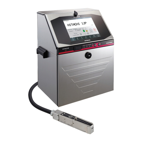
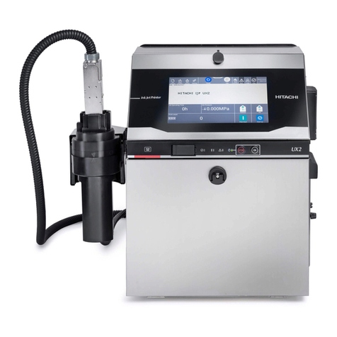
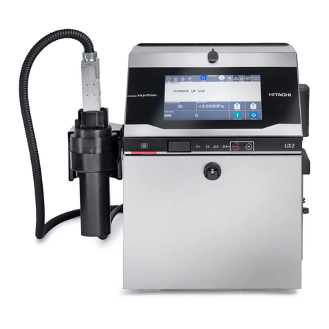
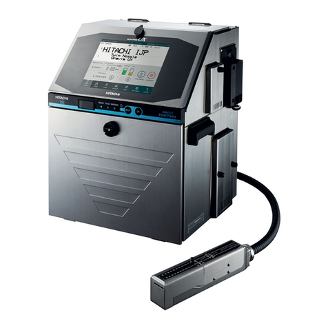
Hitachi UX Twin-Nozzle User manual

HITACHI Printer
Technical Manual
INK JET PRINTER FOR INDUSTRIAL MARKING
Model UX Twin-Nozzle
Thank you for purchasing the Hitachi IJ Printer Model UX Twin Nozzle.
This printer employs a noncontact, ink-jet method to print onto a print target.
This instruction manual describes the basic operating procedures, maintenance procedures, and other detailed
handling procedures of the Hitachi IJ Printer Model UX Twin Nozzle.
If the printer is improperly handled or maintained, it may not operate smoothly and may become defective or
cause an accident. It is therefore essential that you read this manual to gain a complete understanding of the
printer and use it correctly.
After thoroughly reading the manual, properly store it for future reference.
IF you changed the language of screen by mistake,see "7.8 Selecting Languages" in the Instruction Manual.

(2) ●Safety Precautions
SAFETY PRECAUTIONS
●You should observe the precautions set forth below in order to use the product properly and
avoid endangering you or other persons or damaging property. For the purpose of clarifying
the severity of injury or damage and likelihood of occurrence, the precautions are classified
into two categories, WARNING and CAUTION, which both describe hazardous situations
that may arise if you ignore the precautions and perform an incorrect handling or operating
procedure. The precautions in these two categories are both important and must therefore
be observed without fail.
WARNING WARNING is used to indicate the presence of a hazard which
may cause severe personal injury or death if the warning against
performing an incorrect handling procedure is ignored.
CAUTION CAUTION is used to indicate the presence of a hazard which
may cause personal injury or property damage if the warning
against performing an incorrect handling procedure is ignored.
Pictograph Examples
The symbols are used to indicate precautions (including those related to
potential warnings) to be observed. Detailed information is furnished by a picture
within the symbol outline (a shock hazard is indicated by the example shown at
left).
The symbols are used to describe prohibited actions. The details of a
prohibited action are given by a picture within or near the symbol outline (the
example shown at left dictates that you must keep flames away).
The symbols are used to describe required actions. Detailed instructions are
given by a picture within the symbol outline (the example shown at left dictates
that a ground connection must be made).

●Safety Precautions (3)
SAFETY PRECAUTIONS (Continued)
WARNING
●Ensure that there is no flame- or arc-generating device around the
printer.
The ink and makeup are both flammable and may cause fire.
Fire can be generated by matches, lighters, cigarettes, heaters, stoves, gas
burners, welders, grinders and static electricity. Arcs may be generated from
open-type relays, switches, and brush motors. Before handling the ink and
makeup, remove static electricity from your body, peripheral equipment, and so
on. In the interest of safety, position a dry-chemical fire extinguisher near the
printer.
●Since the ink and makeup contain organic solvents, install the printer at
an adequately ventilated location.
Never install the printer in an enclosed space.
Connect exhaust equipment to the printer in order to prevent it from filling
with organic solvent vapor.
Secure adequate space for the ink/makeup handling area and printer
installation site. At least 400 m must be provided per print head.
Ensure that adequate ventilation is provided.
1
2
Installation Environment of Printer
3
CAUTION
●If extraneous noise enters the printer, it may malfunction or break down.
For maximum noise immunity, observe the following installation and wiring
precautions.
Ensure that 100 to 120 VAC or 200 to 240 VAC power cables are not
bundled with other power supply cables.
Insulate the printer main body and print head so that they do not come into
direct contact with the conveyor or other devices.
If the employed print target detector is housed in a metal case, use a plastic
mounting brace for the purpose of insulating the detector from the conveyor
and other devices.
Be sure that the print target detector wiring is not bundled together with other
power supply cables.
1
2
3
4
3

(4) ●Safety Precautions
SAFETY PRECAUTIONS (Continued)
WARNING
●Ensure that all electrical wiring, connections and grounding comply with
applicable cords. Properly connect the printer to its dedicated ground.
Complete the above procedure to avoid electrical shock hazards.
●When welding, keep enough space between the IJ printer and the
welding work area to prevent the arc from starting a fire. Also, be sure to
insulate the printhead and IJ printer frame to keep the welding current
from flowing to the control section of the printer, and to make a separate
ground connection for the printer.
●If you wish to receive ink particles in a beaker, for a printing test for
example, use an electrically conductive beaker and connect the beaker
securely to the ground.
Do not let the tip of the printing head enter the beaker.
Ink particles used for printing are electrically charged. An ungrounded beaker
has a gradually rising charge, possibly catching on or causing a fire.
Grounding
WARNING
●Use an AC voltage of 100 to120 V or 200 to 240 V ±10% only and a
power frequency of 50 or 60 Hz only.
If the above requirements are not met, the electric parts may overheat and
burn, creating a risk of fire or electric shock.
Cable Handling

●Safety Precautions (5)
SAFETY PRECAUTIONS (Continued)
Ink and Makeup Handling
WARNING
●When charging a refill of ink or makeup, exchanging ink, or otherwise
handling ink or makeup, take enough care not to spill ink or makeup.
If you spill any ink or makeup by mistake, wipe it off neatly and promptly with
wiping paper or something similar. Do not close the maintenance cover until
you make sure that the portion you have just wiped is completely dry.
You must pay particular attention when you have spilled ink or makeup inside
the printer and it is not completely dry. Why? Because vapors of ink or
makeup will stay inside the printer and may catch on or cause a fire.
If you find it hard to wipe the printer when it is turned on, stop it with the maintenance
cover open. Power it down, and then wipe it off again.
●If you wish to clean the casing of the printer with wiping paper impregnated
with makeup, be sure to do so with the power off.
Attempting to clean it when the power is on will cause makeup or vapors of makeup
to enter the printer, possibly catching on or causing a fire.
When the cleaning is over, open the maintenance cover and make sure that no
makeup has entered and no vapors remain inside.
●Should you find a leak of ink or makeup inside the printer while the printer is
running or being maintained, wipe it off promptly with wiping paper or
something similar. Then, with the maintenance cover open, stop the printer,
power it down, and repair the leak.
Continuing operation with a leak of ink or makeup will cause an anomaly,
resulting in abnormal printing.
Ink and makeup are flammable. They may therefore catch on or cause a fire.
●The ink and makeup, their waste solution, used wiping papers and empty
containers are flammable. Waste disposal must comply with appropriate
regulations. Consult the appropriate regulatory agency for further information.
CAUTION
●Since the ink and makeup contain organic solvents, observe the following
handling precautions.
When handling the ink or makeup, wear protective gloves and safety goggles to
avoid direct skin contact. If the ink or makeup comes into contact with skin, wash
thoroughly with soap and warm or cold water.
When transferring the ink or makeup to or from a bottle, exercise caution to
prevent it coming into contact with the printer or surrounding articles.
If there is any spillage, immediately wipe it clean using a cloth moistened with
makeup.
●Ink and makeup must be stored as flammable liquids. Storage must comply
with local regulatory requirements. Consult the appropriate regulatory
agency for further information.
1
2

(6) ●Safety Precautions
SAFETY PRECAUTIONS (Continued)
Main Body Handling
WARNING
●Do not insert tweezers, a screwdriver, or any other metal article into the ink
ejection hole in the end of the print head.
When the printer is ready to print, a high voltage (approximately 6 kV) is applied to
the deflection electrode section in the print head.
Exercise caution to avoid electric shock, injury, and fire.
●Do not remove covers and/or screws which are not specified on this manual.
A high voltage is applied to some sections of the printer.
Exercise caution to avoid electric shock and injury.
●Exercise caution to avoid inadvertently disconnecting, forcibly pulling, or
bending piping tubes.
Since the ink and makeup in some portions of piping tubes are pressurized, they
may splash into your eyes or mouth or onto your hands or clothing.
If any ink or makeup enters your eyes or mouth, immediately flush with warm or cold
water and consult a physician.
●While the printer is operating, do not look into the ink ejection hole in the end
of the print head.
Ink or makeup may enter your eyes or mouth or soil your hands or clothing.
If any ink or makeup enters your eyes or mouth, immediately flush with warm or cold
water and consult a physician.
●When ejecting the ink, do it after confirming that there is no one in the ejection
direction.
(Operate with the end of the print head inserted in a beaker, etc.)
●Before servicing the printer, be sure to stop the ink ejection.
Because ink or makeup may splash into your eyes or mouth or onto your hands or
clothing. If any ink or makeup enters your eyes or mouth, immediately flush with
warm or cold water and consult a physician.
●If an earthquake, fire, or other emergency occurs while the printer is engaged
in printing or just turned on, press the Main power switch to turn off the power.
CAUTION
●Only persons who have completed an operator training course for
Hitachi IJP can operate and service the printer.
If the printer is operated or serviced incorrectly, it may malfunction or break down.
●Do not attempt to make repairs for any purpose other than operation or
maintenance.

●Safety Precautions (7)
Related Regulations
WARNING
●Never drain the ink or makeup waste solution into a public sewer system.
Waste disposal must comply with all appropriate regulations.
Consult the appropriate regulatory agency for further information.
●The printer must be managed in compliance with all appropriate regulations.
Read and understand the appropriate Safety Data Sheet (SDS) before using any ink
or makeup.
SAFETY PRECAUTIONS (Continued)
FCC Notice
This device complies with part 15 of the FCC Rules. Operation is subject to the following two
conditions: (1) This device may not cause harmful interference, and (2) this device must accept
any interference received, including interference that may cause undesired operation.
This equipment has been tested and found to comply with the limits for a Class A digital device,
pursuant to part 15 of the FCC Rules. These limits are designed to provide reasonable protection
against harmful interference when the equipment is operated in a commercial environment.
This equipment generates, uses, and can radiate radio frequency energy and, if not installed and
used in accordance with the instruction manual, may cause harmful interference to radio
communications. Operation of this equipment in a residential area is likely to cause harmful
interference in which case the user will be required to correct the interference at his own expense.

(8) ●Safety Precautions
WARNING
<Keep all fire away.>
○Ink and Makeup are flammable.
○All fire must be kept away from the machine.
○Spilled Ink and Makeup must be wiped off and dried up immediately.
<Caution when handling Ink/Makeup>
○Strage must comply with local regulatory requirements .
○Read and understand Safety Data Sheet(SDS).
○Be sure to wear protective gloves and safety goggies.
○If the Ink/Makeup in used is an organic solvent,it must be managed in compliance with the
Ordinance on the prevention or Organic Solvent poisoning.Refer to the "Instruction Manual"and
the "Handling guidance of each ink" for details.
AVERTISSEMENT
< Tenir hors de portée du feu. >
○L’encre et la composition sont inflammables.
○Tenir la machine hors de portée du feu.
○Nettoyez et séchez immédiatement les projections d’encre et de composition.
<Soyez prudent lorsque vous manipulez l’encre/la composition>
○Le stockage doit respecter les obligations réglementaires locales.
○Lisez attentivement la fiche signalétique de sécurité de l’appareil (FSSP).
○Assurez-vous de porter des gants et des lunettes de protection.
○Si l’encre/la composition utilisée est un solvant biologique, vous devez le manipuler
conformément au décret sur la prévention des empoisonnements par solvant biologique.
Reportez-vous au «Mode d’emploi» et aux «Conseils de manipulation de chaque type d’encre»
pour plus de détails.
SAFETY PRECAUTIONS (Continued)

●Contents 1
1. DELIVERED GOODS . . . . . . . . . . . . . . . . . . . . . . . . . . . . 1-1
2. INSTALLING PRECAUTIONS . . . . . . . . . . . . . . . . . . . . . 2-1
3. INSTALLATION CHECK ITEMS . . . . . . . . . . . . . . . . . . . . 3-1
3.1 Print head air purge . . . . . . . . . . . . . . . . . . . . . . . . . . . . . . . . . . . . . . . . . . 3-1
3.2 Setting functions which can be performed . . . . . . . . . . . . . . . . . . . . . . . . . 3-2
3.2.1 Password protection will be canceled in units of Print item . . . . . . . . . . . . . . . . . . . . 3-5
3.3 Selecting login user when power is turned on . . . . . . . . . . . . . . . . . . . . . . 3-9
3.4 The state where the administrator login is returned automatically . . . . . . 3-11
3.5 Human Machine Interface [HMI] setup . . . . . . . . . . . . . . . . . . . . . . . . . . 3-14
4. ELECTRIC SIGNAL CONNECTION . . . . . . . . . . . . . . . . . 4-1
4.1 Wiring precautions . . . . . . . . . . . . . . . . . . . . . . . . . . . . . . . . . . . . . . . . . . . 4-1
4.2 Input/output (I/O) signal connection . . . . . . . . . . . . . . . . . . . . . . . . . . . . . . 4-3
4.2.1 Wiring the I/O line. . . . . . . . . . . . . . . . . . . . . . . . . . . . . . . . . . . . . . . . . . . . . . . . . . . . 4-3
4.2.2 Connection to input/output (I/O) terminals . . . . . . . . . . . . . . . . . . . . . . . . . . . . . . . . . 4-5
4.3 Input/output (I/O) specifications . . . . . . . . . . . . . . . . . . . . . . . . . . . . . . . . . 4-8
4.3.1 Print target detector input. . . . . . . . . . . . . . . . . . . . . . . . . . . . . . . . . . . . . . . . . . . . . . 4-9
4.3.2 Product speed matching function using a rotary encoder . . . . . . . . . . . . . . . . . . . . 4-13
4.3.3 Input function . . . . . . . . . . . . . . . . . . . . . . . . . . . . . . . . . . . . . . . . . . . . . . . . . . . . . . 4-18
4.3.4 Output function. . . . . . . . . . . . . . . . . . . . . . . . . . . . . . . . . . . . . . . . . . . . . . . . . . . . . 4-22
4.3.5 Product speed matching function without a rotary encoder . . . . . . . . . . . . . . . . . . . 4-25
5. COMMUNICATION . . . . . . . . . . . . . . . . . . . . . . . . . . . . . . 5-1
5.1 Overview. . . . . . . . . . . . . . . . . . . . . . . . . . . . . . . . . . . . . . . . . . . . . . . . . . . 5-1
5.2 Setting Communication Environment . . . . . . . . . . . . . . . . . . . . . . . . . . . . . 5-3
5.2.1 Setting Communication Environment. . . . . . . . . . . . . . . . . . . . . . . . . . . . . . . . . . . . . 5-3
5.2.2 Transmission Specifications . . . . . . . . . . . . . . . . . . . . . . . . . . . . . . . . . . . . . . . . . . . 5-5
5.3 Transmission Sequences . . . . . . . . . . . . . . . . . . . . . . . . . . . . . . . . . . . . . . 5-6
5.3.1 Common Transmission Sequences . . . . . . . . . . . . . . . . . . . . . . . . . . . . . . . . . . . . . . 5-6
5.3.2 Printings Transmission . . . . . . . . . . . . . . . . . . . . . . . . . . . . . . . . . . . . . . . . . . . . . . . 5-7
5.3.3 Print Data Recall Transmission . . . . . . . . . . . . . . . . . . . . . . . . . . . . . . . . . . . . . . . . 5-10
5.3.4 Print data registration transmission . . . . . . . . . . . . . . . . . . . . . . . . . . . . . . . . . . . . . 5-11
5.3.5 Print Condition Transmission . . . . . . . . . . . . . . . . . . . . . . . . . . . . . . . . . . . . . . . . . . 5-13
5.3.6 Free Layout Transmission . . . . . . . . . . . . . . . . . . . . . . . . . . . . . . . . . . . . . . . . . . . . 5-21
CONTENTS

2 ●Contents
5.3.7 Calendar Conditions Transmission. . . . . . . . . . . . . . . . . . . . . . . . . . . . . . . . . . . . . . 5-25
5.3.8 User Pattern Character Transmission . . . . . . . . . . . . . . . . . . . . . . . . . . . . . . . . . . . 5-28
5.3.9 On-line/Off-line Transmission Procedure . . . . . . . . . . . . . . . . . . . . . . . . . . . . . . . . . 5-35
5.3.10 Remote Operation Transmission . . . . . . . . . . . . . . . . . . . . . . . . . . . . . . . . . . . . . . 5-36
5.3.11 Time control . . . . . . . . . . . . . . . . . . . . . . . . . . . . . . . . . . . . . . . . . . . . . . . . . . . . . . 5-37
5.3.12 Print item deletion transmission . . . . . . . . . . . . . . . . . . . . . . . . . . . . . . . . . . . . . . . 5-39
5.3.13 Count Reset Transmission . . . . . . . . . . . . . . . . . . . . . . . . . . . . . . . . . . . . . . . . . . . 5-39
5.4 Code Tables . . . . . . . . . . . . . . . . . . . . . . . . . . . . . . . . . . . . . . . . . . . . . . . 5-40
5.4.1 Code Tables . . . . . . . . . . . . . . . . . . . . . . . . . . . . . . . . . . . . . . . . . . . . . . . . . . . . . . . 5-40
5.4.2 Header Table . . . . . . . . . . . . . . . . . . . . . . . . . . . . . . . . . . . . . . . . . . . . . . . . . . . . . . 5-49
5.5 Communication Timing. . . . . . . . . . . . . . . . . . . . . . . . . . . . . . . . . . . . . . . 5-52
5.5.1 Signal Timing . . . . . . . . . . . . . . . . . . . . . . . . . . . . . . . . . . . . . . . . . . . . . . . . . . . . . . 5-52
5.5.2 Response Time. . . . . . . . . . . . . . . . . . . . . . . . . . . . . . . . . . . . . . . . . . . . . . . . . . . . . 5-55
5.6 Communication Monitor Function. . . . . . . . . . . . . . . . . . . . . . . . . . . . . . . 5-60
5.7 Warning Messages. . . . . . . . . . . . . . . . . . . . . . . . . . . . . . . . . . . . . . . . . . 5-62
5.8 Precautions . . . . . . . . . . . . . . . . . . . . . . . . . . . . . . . . . . . . . . . . . . . . . . . 5-65
5.8.1 Notes on Product speed matching Feature Use. . . . . . . . . . . . . . . . . . . . . . . . . . . . 5-65
5.8.2 Notes on Print Condition Transmission . . . . . . . . . . . . . . . . . . . . . . . . . . . . . . . . . . 5-65
5.9 Communication Buffer . . . . . . . . . . . . . . . . . . . . . . . . . . . . . . . . . . . . . . . 5-66
5.9.1 Overview. . . . . . . . . . . . . . . . . . . . . . . . . . . . . . . . . . . . . . . . . . . . . . . . . . . . . . . . . . 5-66
5.9.2 Description of Functions. . . . . . . . . . . . . . . . . . . . . . . . . . . . . . . . . . . . . . . . . . . . . . 5-67
5.9.3 External Communications. . . . . . . . . . . . . . . . . . . . . . . . . . . . . . . . . . . . . . . . . . . . . 5-70
5.9.4 Errors . . . . . . . . . . . . . . . . . . . . . . . . . . . . . . . . . . . . . . . . . . . . . . . . . . . . . . . . . . . . 5-71
6. CIRCULATION SYSTEM WORK AND ADJUSTMENT
METHOD . . . . . . . . . . .6-1
6.1 Circulation control screen operation and contents. . . . . . . . . . . . . . . . . . . 6-2
6.1.1 Circulation control screen operaion . . . . . . . . . . . . . . . . . . . . . . . . . . . . . . . . . . . . . . 6-2
6.1.2 Circulation control contents . . . . . . . . . . . . . . . . . . . . . . . . . . . . . . . . . . . . . . . . . . . . 6-3
6.2 Removing Inner Cover . . . . . . . . . . . . . . . . . . . . . . . . . . . . . . . . . . . . . . . . 6-4
6.3 Replacing the ink . . . . . . . . . . . . . . . . . . . . . . . . . . . . . . . . . . . . . . . . . . . . 6-5
6.4 How to correct ink stream bending and nozzle clogging . . . . . . . . . . . . . 6-11
6.4.1 Nozzle 1 backwash (inluding Nozzle 2) . . . . . . . . . . . . . . . . . . . . . . . . . . . . . . . . . . 6-11
6.4.2 Nozzle orifice disassembly and cleaning . . . . . . . . . . . . . . . . . . . . . . . . . . . . . . . . . 6-13
6.5 Stream alignment . . . . . . . . . . . . . . . . . . . . . . . . . . . . . . . . . . . . . . . . . . . 6-17
6.6 Cleaning the Gutter . . . . . . . . . . . . . . . . . . . . . . . . . . . . . . . . . . . . . . . . . 6-19
6.7 Replacing the ink filter . . . . . . . . . . . . . . . . . . . . . . . . . . . . . . . . . . . . . . . 6-20
6.8 Replacing the recovery filter. . . . . . . . . . . . . . . . . . . . . . . . . . . . . . . . . . . 6-25
6.8.1 Replacing the recovery filter 1 . . . . . . . . . . . . . . . . . . . . . . . . . . . . . . . . . . . . . . . . . 6-25
6.8.2 Replacing the recovery filter 2 . . . . . . . . . . . . . . . . . . . . . . . . . . . . . . . . . . . . . . . . . 6-27
●Contents 3
6.9 Adjusting the pressure . . . . . . . . . . . . . . . . . . . . . . . . . . . . . . . . . . . . . . . 6-28
6.10 Excitation V adjustment . . . . . . . . . . . . . . . . . . . . . . . . . . . . . . . . . . . . . 6-29
6.11 Ink drop state check method. . . . . . . . . . . . . . . . . . . . . . . . . . . . . . . . . . 6-32
6.12 Draining ink from the main ink tank . . . . . . . . . . . . . . . . . . . . . . . . . . . . 6-34
6.13 Testing operation of solenoid valve and pump . . . . . . . . . . . . . . . . . . . . 6-36
6.14 On-screen reminder for maintenance parts replacement. . . . . . . . . . . . 6-37
6.15 Long-term Shutdown . . . . . . . . . . . . . . . . . . . . . . . . . . . . . . . . . . . . . . . 6-39
6.15.1 Process prior to long-term shutdown . . . . . . . . . . . . . . . . . . . . . . . . . . . . . . . . . . . 6-40
6.15.2 Startup process after long-term shutdown . . . . . . . . . . . . . . . . . . . . . . . . . . . . . . . 6-44
7. MAINTENANCE SERVICE . . . . . . . . . . . . . . . . . . . . . . . . 7-1
8. SCHEMATIC DIAGRAMS . . . . . . . . . . . . . . . . . . . . . . . . . 8-1
8.1 Outside Dimensions . . . . . . . . . . . . . . . . . . . . . . . . . . . . . . . . . . . . . . . . . . 8-1
8.2 Electrical Connection Diagram . . . . . . . . . . . . . . . . . . . . . . . . . . . . . . . . . . 8-3
8.3 Circulation System Diagram. . . . . . . . . . . . . . . . . . . . . . . . . . . . . . . . . . . . 8-4
8.4 Tube Connection . . . . . . . . . . . . . . . . . . . . . . . . . . . . . . . . . . . . . . . . . . . . 8-5
9. APPENDIX. . . . . . . . . . . . . . . . . . . . . . . . . . . . . . . . . . . . . 9-1
●Barcode, 2-dimensional code . . . . . . . . . . . . . . . . . . . . . . . . . . . . . . . . . . . . 9-1
●Setting high-speed printing . . . . . . . . . . . . . . . . . . . . . . . . . . . . . . . . . . . . . . 9-6
●Using reverse scan print . . . . . . . . . . . . . . . . . . . . . . . . . . . . . . . . . . . . . . . . 9-9
●Change of Buttons, Icons and Status Colors. . . . . . . . . . . . . . . . . . . . . . . . 9-12
●Icon List . . . . . . . . . . . . . . . . . . . . . . . . . . . . . . . . . . . . . . . . . . . . . . . . . . . . 9-16
●IC Card Function . . . . . . . . . . . . . . . . . . . . . . . . . . . . . . . . . . . . . . . . . . . . . 9-19
●Index . . . . . . . . . . . . . . . . . . . . . . . . . . . . . . . . . . . . . . . . . . . . . . . . . . . . . . 9-28

2-1 ●Installing Precautions
●The employed ink and makeup contain organic solvents. Furnish an
adequate space for the ink/makeup handling area and printer
installation site. A space of at least 400 m must be provided per print head.
Ensure that adequate ventilation is provided. Follow all regulation in your
country.
CAUTION
3
IJ printer
Maintenance area
300
mm
Top view
300
mm
300mm
750mm
2. INSTALLING PRECAUTIONS
●Ensure that there is no flame- or arc-generating device around the printer.
The ink and makeup are both flammable and may cause fire.
Fire can be generated by matches, lighters, cigarettes, heaters, stoves, gas burners,
welders, grinders and static electricity. Arcs may be generated from open-type relays,
switches, and brush motors. Before handling the ink and makeup, remove static
electricity from your body, peripheral equipment, and so on. In the interest of safety,
position a dry-chemical fire extinguisher near the printer.
●Since the ink and makeup contain organic solvents, install the printer at an
adequately ventilated location.
Never install the printer in an enclosed space.
Connect exhaust equipment to the printer in order to prevent it from filling with
organic solvent vapor.
WARNING
2
1
(1) Provide a clearance around the IJ printer for daily operation,
handling, and maintenance access (see the figure at right).
(2) The print head needs to be cleaned with the makeup while the
printeris operatedandstopped (daily maintenance). Adopta fixed
structure in consideration of print head cover and print head
removal.
(3) Installation must be completed so that no vibration will be applied to
the IJ printer main body, print head, or print head cable.
If they are vibrated, print quality deterioration and print irregularity
may be incurred (the maximum permissible vibration value is
1.96m/s ).
(4) The IJ printer main body must be installed with a levelness error of
not over ±1°.
(5) The IJ printer main body must be electrically insulated from the
other equipment (conveyors, packing machines,etc.), photoelectric
switches, and the rotary encoder.
(6) The standard distance between the printing head and the object to be
printed on is as indicated in the right-hand table.
The smaller the clearance between the print head and print target,
the smaller the character height and the better printing.
(7) The IJ printer proper requires maintenance as the occasion may
demand including replenishment of ink and makeup and
replacement of filter.
(8) If ambient humidity is 85 to 90%RH, you must purge inside of print
head by air. It is necessary for dry-clean air, regulator for pressure
of air and air filter. (Quantities of the air are 1L / minutes.)
* Leave a maintenance area of
at least 20 cm for the upside
of printer.
Distance between the printing head
and the object to be printed on
Nozzle diameter Distance
65μm10 to 30mm
2

●Installing Precautions 2-2
Upward printing Lateral printing Downward printing
Print head cable
end of the position
1m
1.5m
Print head
Print head cable
Main body installation surface
IJ printer
main body
(9) When installing the print head and print head cable, comply with the following conditions or it will
increase the risk of degraded performance of the ink supply and ink recovery behavior.
When positioning the end of the print head above the printer main body installation surface,ensure
that the distance between the end of the print head and the installation surface does not exceed 1.5 m.
When positioning the end of the print head below the printer main body installation surface, ensure
that the distance between the end of the print head and the installation surface does not exceed 1 m.
2
1
Print head
Print head cable
Bend R 0.5m
(10) When using the printer for upward or lateral printing, ensure that the rising print head cable upper end
is positioned not more than 0.5 m above the print head.
(11) If you fixed the print head, ensure that the minimum bend radius of the print head cable is at least 150 mm.
Handle the headcable with care when wiring it.
If the minimum bend radius is less than 150mm, the tubes and wires inside the headcable might be broken.
(12) The ink stream may bend for some reason or other (due, for instance, to dirt).
The facilities positioned in the direction of ink ejection should be partially covered as needed to avoid ink
accumulation.

2-3 ●Installing Precautions
(14) If you try to fix the print head with a magnetic substance (such as iron), the cover switch will
malfunction resulting in an "Cover Open" error.
This, you must only use nonmagnetic resins or metals for fixing the print head.
(15) In the case of carrying the printer proper, use the handles in the drawing below.
Connect a duct to this port
(50 mm in diameter).
Exhaust duct
connection port
(13) When connecting an exhaust duct to the printer, install a damper and adjust the wind velocity at the intake
port to 0.3 to 0.5 m/s. (Use an anemometer for verification. If the wind velocity is too high, the makeup
consumption increases.)

●Print head air purge 3-1
3.1 Print head air purge
If the makeup remains in the electrode section after cleaning or if you use the IJ
printer at a high humidity, moisture condensation may occur within the print head,
causing leakage from the deflection electrode section. It is also important to
remember that dust or splashed ink accumulation on the deflection electrode
section may cause leakage. Performing the following air purge procedure for the
print head interior is effective in preventing such leakage.
3. INSTALLATION CHECK ITEMS
If the air-purge amount is excessive, print irregularities may occur.
After air-purge pressure adjustment, be sure to perform a printing test to
verify the printing results.
(1) Situations requiring an air purge
When the printer is used in a highly humid place such as a beer or other beverage can line
(If you use the printer in an environment in which the relative humidity is 85% or higher,
complete the print head air-purge procedure).
When a water drainage blow sequence is performed before printing.
When the printer is used in a place where a considerable amount of paper powder or other dust
exists.
When the printing distance is short so that the end of the print head is splashed with ink.
When you use inks that are indicated on the handling guidance of each ink to complete
air-purge procedure.
(2) Air-purging procedure
Introduce clean dry air into the print head air purge connection port (Rc 1/8 (PT 1/8)×screw) in
the rear of the printer main body at a pressure of about 0.1 to 0.3 MPa. If it is possible that the
employed air tanks oil or water, turn it into clean dry air with an air filter, micro-mist separator, or
the like before introducing it into the printer main body.
1
2
3
4
5
NOTICE
Max. tightening torque:1.5N m
Back of body
Print head air purge
connection port
Made of resin. Be careful not to
tighten too tightly when connecting
with a metal joint.
Air source
(clean dry air)
(capacity: Approx. 1L/min) Pressure reducing valve
Pressure gauge
0.1 0.3MPa
~
・

3-2 ●Setting functions which can be performed
4
3.2 Setting functions which can be performed
(1) Functions
●Sets whether or not each function is enabled or disabled for each login user.
●The operation buttons of disabled functions are not displayed or the screen cannot be entered.
●”User conditions setup” and “Using environment setup” can be started when the administrator logs in.
●The function restrictions state can be checked at the function restrictions screen. (Refer to “Instruction
manual 5.5 Checking functions that can be performed”)
Protected functions
Item Protected function name
Edit message
●Edit message
●Calendar conditions
●Substitution rules setting
●Count conditions
Select message ●Select message
Save message ●Save message
●Overwrite message
Print specifications ●Print specifications
●Various print setup
●Adjust print parameters
Print format ●Print format
●Adjust inter-character space
Maintenance
[Auxiliary functions]
●Manage messages/group
●Create user pattern
●Calibrate touch screen coordinates
●Copy data (IJP→USB)
●Copy data (USB→IJP)
●Edit standard pattern
●Edit substitution rules
●Select language
[Environment setup]
●User environment setup
●Date/time setup
●Communication environment setup
●Touch screen setup
[Maintenance work]
●Operation management
●Excitation V update
●Circulation control
●Solenoid valve/pump test
●Periodic replacement parts mgmt.
Password setup ●Password setup

●Setting functions which can be performed 3-3
Login management menu
2018.07.0712:45
[Stop ]
Login history Select login user Password setup
User conditions
setup
Using environment
setup
Create new user ID Delete user ID
Makeup Ink
Manual Startup
HOME
Com=0
Back
Sets whether or
not to select a
user which logs
in when power
is turned on.
Sets function
restrictions for
each user.
Sets the password.
Delete the user.
Create the new user.
Press Login management of the Environment setup menu.
The Login management menu is displayed.
Log in as a user with administrator rights when User conditions setup or Using environment setup are
not displayed on Login management menu.
1
(2) Operation
The administrator is logged in.
Press User conditions setup .
The User conditions setup screen is displayed.
A user list is displayed.
2
User conditions setup
2018.07.0712:45
[Stop ]
admin user2 user3
user4 user5
Current user ID : admin
user5
Com=0
Back

3-4 ●Setting functions which can be performed
User conditions setup
2018.07.0712:45
[Stop ]
Edit message
Select message
Save message
Print specifications
Print format
Maintenance
Password update
ID:5
Administrator rights
user5
access protect
access protect
access protect
access protect
access protect
access protect
access protect
Users Administrator
Makeup Ink
Com=0
Manual
HOME
Startup
OK
Password
setup
Cancel
Sets function
restrictions.
Displays the kind
of administrator
rights.
OK
Password
setup
Modifies the user
name.
Select user5 .
“user5” settings are displayed.
3
Select the administrator rights.
4
Select “access” or “protect” for each function item.
5
Press Password setup and set the password.
6
Press OK .
The administrator rights, function restrictions, user name, and password for user “user5” are set.
7
An error message appears when the entry in the old password input field does not agree
with the current password.
However, the error does not occur if you type in "IGNOREPW" as the password.
Use this word if you forget your password.

●Setting functions which can be performed 3-5
Menu
Change
message
Select
message
Overwrite
message
Adjustprint
parameters
Operation
management
SaveandBack
:Multiple print formats can be mixed.
<Format Setup>
Print
format
Edit
message
Print
spec.
Various
printsetup
Individual
setup
Overall
setup
Freelayout
:Character size and inter-character space set
value are matched at all lines.
Only 1 column can be input.
:An arbitrary position can be set for each print
item.
Back
Twin
3.2.1 Password protection will be canceled in units of Print item
(1) Overview
●When Password protection is valid, it can be canceled in units of Print item.
●When Administrator logs in, Password protection can be canceled.
(2) Operation
●The character input is made as follows.
USE BY ・ 18.07.07・
(Column 1) (Column 2)
●For “user5” whose “Administrator rights” is “Users", set “Edit message” to “protect”.
●Password protection for Column 2 will be canceled.
Administrator logs in.
1
As described in Section 3.2 “Setting functions which can be performed”, make
“User conditions setup” enabled for “user5” and set “Edit message” to “protect”.
At this time, Administrator still logs in.
2
Return to “Print description” screen from “Login management menu”.
3
Press Change message on “Print description” screen.
“Change message” screen will be displayed.
4
Change message
Edit message

3-6 ●Setting functions which can be performed
Edit message
2018.07.0712:45
[Stop ]
Message name[SAMPLE 1 ]
Column1
Item101
Char.count
16/500
1 2 3 4 5 6 7 8 9 0
Backspace
+ − × / ( ) . : , !
Dupli-
cate Paste
" # $ % & ¥
Space
etc.
▽
Calendar
/count
★◎△
Logo Delete
110 20
Insert
ABCabc
Cal.
cond.
Count
cond.
123‥
Sign
'■[]
=?<>;*_
Over-
write
USE BY 18.07.07
USE BY 18.07.07
USE BY ・
Makeup Ink
Com=0
Manual
HOME
Startup
Password
protection
Print
spec.
Pint
format
Twin
Back
←
《 》
→
0:AB
→
N2
− +
Password protection
2018.07.0712:45
[Stop ]
Message name[SAMPLE 1 ]
USE BY 18.07.07
USE BY 18.07.07
Makeup Ink
Back
protectall
Twin
pro-
tect access
Com=0
Manual
HOME
Startup
0:AB
→
N2
− +
Press Edit message on “Change message” screen.
“Edit message” screen will be displayed.
5
Press Password protection on “Edit message” screen.
“Password protection” screen will be displayed.
The character input of all the items is restricted by showing shaded characters.
The cursor is placed on Column 1.
6
Password protection
Next item
Table of contents
Other Hitachi Printer manuals

Hitachi
Hitachi IJ PH User manual

Hitachi
Hitachi DDS 40 User manual

Hitachi
Hitachi IJ RX2-SD160 User manual

Hitachi
Hitachi SL1 User manual

Hitachi
Hitachi IJ UX2 User manual

Hitachi
Hitachi PXR-D User manual

Hitachi
Hitachi PH User manual

Hitachi
Hitachi IJ UX User manual

Hitachi
Hitachi UX2 Series User manual

Hitachi
Hitachi IJ RX2 User manual

Hitachi
Hitachi UX Twin Nozzle User manual

Hitachi
Hitachi UX Assembly instructions

Hitachi
Hitachi SCI User manual

Hitachi
Hitachi RX2 User manual

Hitachi
Hitachi UX2 Series User manual

Hitachi
Hitachi UX2 Series User manual

Hitachi
Hitachi PB Series User manual

Hitachi
Hitachi RX User manual

Hitachi
Hitachi RX User manual

Hitachi
Hitachi SL-1D User manual