3
1.Communication overview
1.1 Overview
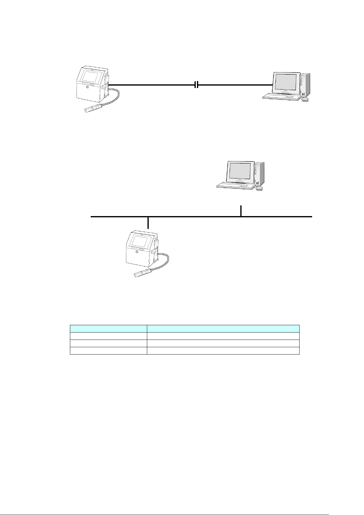
1.1.1 Serial communication
The functions described in this document are used to transmit printings and their registration
numbers and enter them into the IJ printer with an external device connected to the IJ printer
via an RS-232C serial communication line. Connect the USB serial converter to the USB port
of the IJ printer and use RS-232C serial communication via the USB serial converter.
1.1.2 Ethernet communication (Tunnel communication)
Ethernet communication supports the same contents as RS-232C serial communication.
Because it uses the same mode of communications as previous models, if RS-232C serial
communication is already employed for the IJ Printer, you can create a communications program
for the host device using this asset.Please refer to Communication User’s manual (Serial Communication)
for details of this function.
1.1.3 Ethernet communication (Modbus communication)
This function allows you to change the settings of the IJ printer by transmitting the
print contents, print specifications, etc. between the external device and the IJ printer
using the LAN environment. Modbus is an industrial multi-vendor network using
Ethernet, and its communication specification is adopted as an open standard in
various industrial equipment. Messages that the IJ printer voluntarily outputs, such as
status output and print content output, do not correspond.
For the Modbus communication, it is necessary to develop a communication program
on the external device side.
1.1.4 Ethernet communication (OPC-UA communication)
This function allows you to change the settings of the IJ printer by transmitting the
print contents, print specifications, etc. between the external device and the IJ printer
using the LAN environment.
OPC-UA
is an industrial multi-vendor network using
Ethernet, and its communication specification is adopted as an open standard in
various industrial equipment. Messages that the IJ printer voluntarily outputs, such as
status output and print content output, do not correspond.
For the OPC-UA communication, it is necessary to develop a communication program
on the external device side.
1.1.5 Ethernet communication (EtherNet/IP communication)
It is a function to communicate with an IJ Printer via Ethernet from an external device using
the network environment.
EtherNet/IP is an industrial multi-vendor network using Ethernet, and its communication
specification is adopted as an open standard in various industrial equipment.
EtherNet/IP communication has two communication functions: “Message communication
(Explicit communication)” that communicates at an arbitrary timing and “Cyclic
communication (Implicit communication)” that communicates at a fixed cycle.
For the EtherNet/IP communication, it is necessary to develop a communication program on
the external device side.