Hitecsa Verne WPHA HE Series User manual

1
IOM_WPHBA HE-WPHA HE_091a1201_207815_180701_EN
HORIZONTAL WATER-AIR COMPACT PACKAGED UNITS
WPHA HE / WPHBA HE
WPHA HE WPHBA HE
Cooling only Heat pump
HORIZONTAL WATER-AIR COMPACT PACKAGED UNITS
INSTALLATION, OPERATION AND MAINTENANCE MANUAL
IOM_WPHBA HE-WPHA HE_091a1201_207815_180701_EN
Models: 091│121│141│171│201│251│351│401│501│ 701│751│1001│1201
Cooling capacity: 2.4 a 41.0 kW
Heating capacity: 2.3 a 37.9 kW

2
IOM_WPHBA HE-WPHA HE_091a1201_207815_180701_EN
HORIZONTAL WATER-AIR COMPACT PACKAGED UNITS
WPHA HE / WPHBA HE
Thank you for trusting the Hitecsa Products. Our company has been offering the market an extended range of specialized
units for air conditioning and cooling installations for over 35 years. Our approach is based on efficiency, adaptability,
usability and practical solutions. This has been the hallmark of our product catalogue.
The versatility of our factory allows us to contribute solutions, almost tailored to each project’s specifications, in search of
a solution to every problem that arises in design and implementation of air conditioning installations.
From all of us at Hiplus Aire Acondicionado, once again, thank you very much.

3
IOM_WPHBA HE-WPHA HE_091a1201_207815_180701_EN
HORIZONTAL WATER-AIR COMPACT PACKAGED UNITS
WPHA HE / WPHBA HE
INDEX
INTRODUCTION ............................................................................................................................4
REGULATIONS AND CERTIFICATIONS.......................................................................................5
SAFETY PRECAUTIONS...............................................................................................................6
TECHNICAL SPECIFICATIONS ....................................................................................................8
TRANSPORT & RECEPTION ......................................................................................................14
INSPECTION AT RECEPTION ........................................................................................................................................... 14
RIGGING......................................................................................................................................................................... 14
STORAGE........................................................................................................................................................................ 14
INSTALLATION............................................................................................................................15
INSTALLATION LOCATION .............................................................................................................................................. 15
UNIT SETTLEMENT ......................................................................................................................................................... 15
SERVICE AREA ................................................................................................................................................................ 15
WEIGHT DISTRIBUTION (KG)........................................................................................................................................... 15
DIMENSIONS AND WEIGHT............................................................................................................................................ 16
WATER DRAIN................................................................................................................................................................ 21
AIR DUCTS...................................................................................................................................................................... 21
INSTALLATION OF WATER PIPES .................................................................................................................................... 22
Preliminary information ............................................................................................................................................. 22
Components................................................................................................................................................................ 22
Safety elements .......................................................................................................................................................... 22
Risk of frost................................................................................................................................................................. 22
Glycol additions .......................................................................................................................................................... 22
WPHA /WPHBA HYDRAULIC CIRCUIT AND ITS COMPONENTS ...................................................................................... 23
ELEMENTS AND HYDRAULIC CONNECTIONS OF THE INSTALLATION DIAGRAM............................................................. 24
ELECTRICAL CONNECTIONS ........................................................................................................................................... 25
Thermostat connections. ............................................................................................................................................ 25
OPERATION ................................................................................................................................27
BEFORE START UP .......................................................................................................................................................... 27
START UP ....................................................................................................................................................................... 27
OPERATING LIMITS ........................................................................................................................................................ 28
Cooling cycle............................................................................................................................................................... 28
Heating cycle .............................................................................................................................................................. 28
TH TUNE CONTROL ........................................................................................................................................................ 29
ON-OFF CONTROL.......................................................................................................................................................... 29
TEMPERATURE ADJUSTMENT........................................................................................................................................ 29
SYSTEM MODES .......................................................................................................................................................... 29
Indoor Fan Modes:...................................................................................................................................................... 29
Warnings and Information signals ............................................................................................................................. 29
Description of the Warning Codes .............................................................................................................................. 29
Alarms ........................................................................................................................................................................ 29
Alarm Codes Reset...................................................................................................................................................... 29
Description of the Alarm Codes .................................................................................................................................. 30
MAINTENANCE ...........................................................................................................................31
REFRIGERANT CHARGE .................................................................................................................................................. 33
FAN WITH EC MOTOR .................................................................................................................................................... 33
Diagnosis / Failures .................................................................................................................................................... 34
APPENDIX: SAFETY DATA R410A.............................................................................................36

4
IOM_WPHBA HE-WPHA HE_091a1201_207815_180701_EN
HORIZONTAL WATER-AIR COMPACT PACKAGED UNITS
WPHA HE / WPHBA HE
INTRODUCTION
Purpose of this Manual
This manual and any other instructive document attached as refrigeration lines design, electrical diagrams,
etc. have been written to allow a correct installation, commissioning and maintenance of the unit. Therefore
it is essential to read the instructions with due attention.
Verify that all the necessary information for the correct installation of the system is included in the manuals
supplied with this unit and/or the rest of the indoor units, accessories, etc. Otherwise, the manufacturer
declines any responsibility for any damage to persons, animals or things, as a result of improper use of the
unit and/or failure to observe these instructions.
In case of different interpretations and/or errors the documentary priority will be: 1. Characteristics plate of
the unit, 2. IOM (this document), 3. EDM, technical catalogue, 4. UM user manuals.
Conservation of the Manual
This manual and the electric diagram of the unit must be retained and remain available to the operator for any further consultation.
Updating the Data
The continuous improvement in design and performance to which we are committed gives us the right to modify the specifications of our
products without prior notice.
Electrical Supply
Check that the electrical network features are in accordance to data shown in the data nameplate of the unit.
Local Safety Regulations
Observe and analyse all possible causes of accidents that may arise in the place or places of installation of the units, check means and
tools to use, etc. It is not possible to anticipate each and every one of the potential circumstances of danger in this manual. Respect the
valid local security standards during installation.
Principles of Security on Installation
The unit is designed and built in a way that does not pose a risk to the health and safety of people. Appropriate solutions for the project
have been adopted to eliminate the possible causes of risk in the installation.
Packaging and Replacement of Equipment
The material of the package (plastic bags, insulatingmaterials, nails, etc.) is a potential source of danger. Consequently,
it should be kept out of the reach of children and properly recycled according to the valid local safety regulations.
This product should not be mixed with household waste at the end of its life. Due to the refrigerant, oil and other
components contained in this product, it must be dismantled by professional installers, all waste should be
sent, according to its nature to recycling, composting or treatment plants, or an authorized management agency in
accordance with current local legislations.
Utilization
The unit will be used only for the reason it has been conceived. Any other use does not imply any kind of compromise or link for the
manufacturer.
5
IOM_WPHBA HE-WPHA HE_091a1201_207815_180701_EN
HORIZONTAL WATER-AIR COMPACT PACKAGED UNITS
WPHA HE / WPHBA HE
INTRODUCTION
Incorrect Operation
In case of breakdowns or operation faults, turn off unit.
Periodic Inspections and Maintenance
Carry out periodic inspections to detect possible damaged or broken pieces. If they are not repaired it could cause
damage to people or stuff. Before executing any maintenance operation, cut off the unit power supply.
Make sure to leave the maintenance areas open. If these areas have to be necessarily invaded by the construction of
air supply and/or lateral return ducts. Verify that the design of the ducts allow the access to the fans and the change of
the filters or that these are accessible from the other lateral.
All operations should be carried out in accordance with local safety regulations.
Repairing Operations
The reparations should be always and exclusively made by trained personal authorized by the manufacturer using
original spares. The safeties of the unit could be affected due to the failure to comply with these warnings.
Modifications
The manufacturer will not respond to the warranty and to the possible damages of the unit in case of electrical and/or mechanical
modifications. The unauthorized manipulation, reparation or modification of the unit will automatically invalidate the warranty.
Refrigerant
This product is hermetically sealed and contains R-410A which is a HFC fluorinated greenhouse gas.
This product is hermetically sealed and its operation depends on the use of R-410A which is a HFC fluorinated greenhouse gas.
REGULATIONS AND CERTIFICATIONS
ISO 9001 CERTIFICATION: HIPLUS AIRE ACONDICIONADO S.L., trying always to find the maximum satisfaction of
costumers, has obtained the ISO 9001:2015 Quality System referred to its production activity. This will result in a
continuous determination to improve quality and reliability of all our products; commercial activities, design, raw materials,
production and after-sales service, are the means to reach our goal.
CE MARKING: Our machines have got the CE mark, in conformity with the essential requirements of the applicable EC
directives and their last modifications as well as with the national legislation of each country.
EUROVENT CERTIFICATION: HITECSA participates in the EUROVENT Certification program. Check certified products
on the web.

6
IOM_WPHBA HE-WPHA HE_091a1201_207815_180701_EN
HORIZONTAL WATER-AIR COMPACT PACKAGED UNITS
WPHA HE / WPHBA HE
SAFETY PRECAUTIONS
Before starting any installation, service or maintenance operation, turn off the main power switch in
order to avoid electrical shock that may cause personal damages.
In case of folding electrical panels, before folding them up in order to access to the interior of the
machine, it is MANDATORY to disconnect the power supply hose from the electrical voltage, IT MUST
ALWAYS BE FREE OF VOLTAGE for this operation
DANGER
Do not touch or adjust the safety elements inside of any unit of the system. In repairs use only original spare parts
and install them properly in the same position where old parts were placed.
The installation and maintenance of air conditioning equipment could be dangerous because the system is under
pressure, some of its elements have high temperatures and include electrical components.
Do not install the unit into an explosive atmosphere.
If it was necessary to open the electrical panel and access the inside of the machine it is MANDATORY to
disconnect the power supply hose from the machine. It MUST BE FREE OF VOLTAGE for this operation.
It is generally forbidden to carry out work on electrical live parts. Protection class of the device when it is complete
opened is IP00! Be careful, do not touch hazardous voltages directly.
Check the safe isolation from the supply using a two-pole voltage detector.
Even after disconnecting the main voltage, life-threatening charges can appear between the protective ground
“PE” and the main connection.
Units with water-air, water-water or refrigerant-water heat exchangers must be convenientlyprotected from breaks
by freezing when the room temperature can reach values lower than 5 ºC.
In this case, it is mandatory heat, remove completely the water or add antifreeze to ensure that the freezing point
is always lower than the room temperature.
When the motor runs independently due to air flowing through or if it continues to run down after being
turned off, dangerous voltages of over 50 V can arise on the internal connections of the motor through operation
of the generator.
When there are EC motors or motors with variable speed control, the protective earth is conducting high discharge
currents (depending on the switching frequency, current source voltage and motor capacity). Earthing in
compliance with EN specifications shall therefore be observe even for testing and trial conditions (EN 50 178, Art.
5.2.11). Without earthing, dangerous voltages can be present on the motor housing.
Through use of capacitors, danger of death exists even after switching off the device in case of direct contact with
conductive parts or with parts that carry voltage due to fault condition. It is only allowed remove or open the
housing of the controller when the power supply cable is disconnected and after a waiting time of 3 minutes.
The warranty of the unit will not respond to the damages caused by frozen water.
WARNING!

7
IOM_WPHBA HE-WPHA HE_091a1201_207815_180701_EN
HORIZONTAL WATER-AIR COMPACT PACKAGED UNITS
WPHA HE / WPHBA HE
SAFETY PRECAUTIONS
Only qualified and trained service staff (technical service) must make the installation, commissioning and carry
out maintenance works. Unqualified personnel can only make basic tasks such as cleaning and replacement of
filters, etc.
Prevent access to children so they cannot play with the appliances.
In every visit, all precautions must be taken into account: those recommended in the installation, operation and
maintenance instructions, as well as the ones indicated in labels of the unit. Do not forget to strictly follow any
other safety precautions.
DO NOT introduce objects into the air inlets or outlets that can be drawn into the fan, people, etc.
Use safety glasses, work gloves and any other safety accessory necessary.
The fan / motor may switch on and off automatically for functional reasons.
After power failure or main disconnection an automatic restart of the fan takes place after voltage return!
Wait for the fan to come to a complete standstill before approaching it!
In the AC external rotor motor the external rotor turns during operation!
For brazing operations use a quenching cloth and take precautions to have at close distance a fire extinguisher.
This product contains fluorinated greenhouse gases, its leakage can cause displacement of air and cause
insufficient oxygen to breath.
The decomposition of fluorinated gases when being burned due to e.g. brazing operations, may cause the
existence of highly toxic and corrosive gases.
Must follow all safety recommendations.
Product precautions
The equipment accomplishes the current technical standards at the moment of its delivery and basically it is considered
secure. The unit and its corresponding accessories should only be assembled and operate if they are in perfect conditions
and in agreement with the instructions manual of the manufacturer. Utilizations which are not in accordance with the
technical specifications of the unit (Name plate and appendix / technical data) might cause defects and other kind of
damages.
ATTENTION!
The responsibility of all personal and material damages caused by an unplanned or inappropriate use
will be on the person or operating company of the unit, and will not be on its manufacturer.
WARNING!
8
IOM_WPHBA HE-WPHA HE_091a1201_207815_180701_EN
HORIZONTAL WATER-AIR COMPACT PACKAGED UNITS
WPHA HE / WPHBA HE
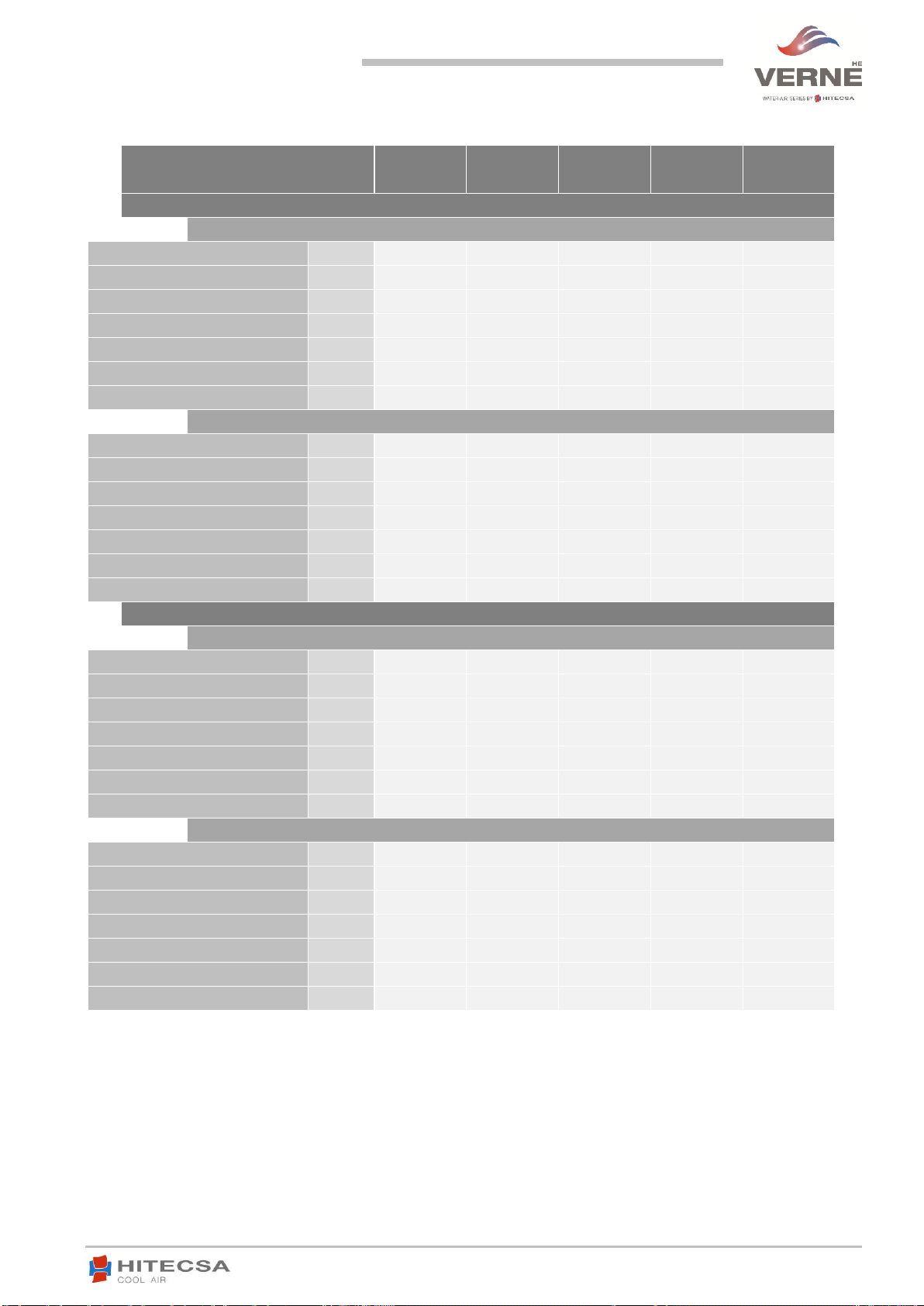
TECHNICAL SPECIFICATIONS
VERNE HE SERIES
091
121
141
171
201
WPHA / WPHBA
COOLING CAPACITIES (1)
Nominal cooling capacity (1)
kW
2.36
3.18
3.86
4.82
5.83
Power input (1)
kW
0.72
0.94
1.06
1.11
1.56
EER Coefficient (1)
kW / kW
3.3
3.37
3.64
4.35
3.75
SEER Coefficient (1)
kW / kW
2.94
3.06
3.03
3.74
3.35
ηs,c (1)
109.5
114.4
113.3
141.8
126.1
Water flow
m³/h
0.5
0.67
0.81
1.01
1.23
Differential pressure
kPa
8.3
14.3
20.3
17.3
24.9
COOLING CAPACITIES (2)
Nominal cooling capacity (2)
kW
2.64
3.56
4.33
5.38
6.51
Power input (2)
kW
0.52
0.68
0.76
0.83
1.12
EER Coefficient (2)
kW / kW
5.11
5.24
5.69
6.49
5.82
SEER Coefficient (2)
kW / kW
3.7
3.87
3.82
4.55
4.23
ηs,c (2)
139.8
146.7
144.6
174.2
161.2
Water flow
m³/h
0.56
0.75
0.91
1.13
1.37
Differential pressure
kPa
10.3
17.6
25.2
21.3
30.4
WPHBA (Heat pump units)
HEATING CAPACITIES (3)
Heating capacity (3)
kW
2.26
3.16
3.86
4.56
5.75
Power input Heat (3)
kW
0.68
0.85
1.12
1.04
1.44
COP Coefficient (3)
kW / kW
3.31
3.72
3.46
4.37
4.0
SCOP Coefficient (3)
kW / kW
2.87
3.22
2.99
3.78
3.22
ηs,h (3)
106.7
120.8
111.5
143.4
130.7
Water flow
m³/h
0.47
0.66
0.8
0.96
1.23
Differential pressure
kPa
7.4
13.9
19.9
15.8
24.9
HEATING CAPACITIES (4)
Heating capacity (4)
kW
1.76
2.47
3.03
3.57
4.49
Power input Heat (4)
kW
0.6
0.75
0.99
0.96
1.28
COP Coefficient (4)
kW / kW
2.91
3.27
3.05
3.72
3.52
SCOP Coefficient (4)
kW / kW
2.52
2.83
2.63
3.22
3.05
ηs,h (4)
%
92.8
105.2
97.1
120.7
113.9
Water flow
m³/h
0.36
0.51
0.62
0.75
0.97
Differential pressure
kPa
4.5
8.6
12.4
10.0
16.1
1) Nominal conditions. Refrigeration tower: Indoor air 27/19 ºC. Condenser water: inlet 30 ºC / outlet 35 ºC (Inlet
partial loads 26/22/18).
2) Geothermal conditions: Indoor air 27/19 ºC. Condenser water: inlet 10 ºC / outlet 15 ºC (Inlet partial loads
10/10/10).
3) Underground water conditions: Indoor air 20 ºC. Evaporator water: inlet 10 ºC, unit water flow 100 % outlet 7
ºC.
4) Brine conditions: Indoor air 20 ºC. Evaporator water: inlet 0 ºC, unit water flow 100 % outlet -3ºC.

9
IOM_WPHBA HE-WPHA HE_091a1201_207815_180701_EN
HORIZONTAL WATER-AIR COMPACT PACKAGED UNITS
WPHA HE / WPHBA HE
TECHNICAL SPECIFICATIONS
VERNE HE SERIE
091
121
141
171
201
REFRIGERANT
Type
R-410A
Global warming potential (GWP) (5)
2088
Refrigerant load WPHA
kg
0.4
0.4
0.4
0.5
0.55
Refrigerant load WPHBA
kg
0.7
0.6
0.9
1.5
1.2
COMPRESSOR
Type
Rotary
Quantity
1
Voltage
V / ~ / Hz
230 / I / 50
Oil type
ESTER
VG74
ESTER
VG74
POE
ESTER
VG74
ESTER
VG74
Oil quantity in compressor
L
0.35
0.40
0.44
0.48
0.62
EVAPORATOR FAN
Type
Radial with EC motor
Quantity
1
Size
mm
190
190
190
250
250
Nominal air flow
m³/h
500
600
700
900
1100
Static pressure available
Pa
25
25
25
25
25
Maximum pressure available
Pa
515
410
300
760
700
Motor nominal Capacity
kW
0.2
0.2
0.2
0.5
0.5
Nominal speed
r.p.m.
2500
2924
3365
1368
1640
Power supply
V / ~ / Hz
230 / I / 50
INDOOR HEAT EXCHANGER
Type
Coil with aluminium fins and copper pipes
Frontal area
m²
0.165
0.165
0.165
0.188
0.188
Fin spacing
mm - (")
2.1 - 3/8”
OUTDOOR HEAT EXCHANGER
Type
Brazed plates
Quantity
1
Water connections (gas male screw)
(")
¾”
Number of plates
16
16
16
22
22
ELECTRICAL DATA
Voltage
V / ~ / Hz
230 / I + N / 50
Maximum current input
A
5.78
7.18
8.28
9.63
12.63
Start-up current
A
20.98
22.98
35.68
28.13
45.03
DIMENSIONS AND WEIGHT
Length
mm
1055
1055
1055
1055
1055
Width
mm
560
560
560
560
560
Height
mm
410
410
410
470
470
Conduit
mm x
mm
225x225
225x225
225x225
236x296
236x296
Weight
kg
60
62
65
75
77
SOUND LEVEL
Sound pressure at 2 m
dB (A)
55
55
56
57
59
Total sound power (Lw)
dB (A)
71.5
72
72.5
73.5
75.5
5) GWP: Global warming potential (climatic) of 1 kg of greenhouse gas relative to 1 kg of CO2, calculated in terms
of 100-year warming potential.
10
IOM_WPHBA HE-WPHA HE_091a1201_207815_180701_EN
HORIZONTAL WATER-AIR COMPACT PACKAGED UNITS
WPHA HE / WPHBA HE
TECHNICAL SPECIFICATIONS
VERNE HE SERIE
251
351
401
501
WPHA / WPHBA
COOLING CAPACITIES (1)
Nominal cooling capacity (1)
kW
7.47
11.31
13.06
16.61
Power input (1)
kW
1.78
2.85
3.24
3.44
EER Coefficient (1)
kW / kW
4.19
3.97
4.03
4.82
SEER Coefficient (1)
kW / kW
3.77
3.61
3.6
4.5
ηs,c (1)
142.7
136.4
136
172.2
Water flow
m³/h
1.57
2.38
2.75
3.5
Differential pressure
kPa
14.5
31.3
40.9
21.3
COOLING CAPACITIES (2)
Nominal cooling capacity (2)
kW
8.35
12.66
14.62
18.55
Power input (2)
kW
1.33
2.05
2.33
2.49
EER Coefficient (2)
kW / kW
6.3
6.18
6.29
7.46
SEER Coefficient (2)
kW / kW
4.63
4.58
4.56
5.69
ηs,c (2)
177.2
175.1
174.6
219.8
Water flow
m³/h
1.76
2.67
3.08
3.91
Differential pressure
kPa
17.9
38.8
50.5
26.2
WPHBA (Heat pump units)
HEATING CAPACITIES (3)
Heating capacity (3)
kW
7.47
11.61
13.44
15.22
Power input Heat (3)
kW
1.71
3.33
3.08
3.17
COP Coefficient (3)
kW / kW
4.38
3.48
4.36
4.8
SCOP Coefficient (3)
kW / kW
3.8
3.02
3.77
4.16
ηs,h (3)
144
112.9
142.8
158.6
Water flow
m³/h
1.54
2.4
2.8
3.5
Differential pressure
kPa
14.0
31.8
42.3
21.3
HEATING CAPACITIES (4)
Heating capacity (4)
kW
5.86
9.11
10.55
11.89
Power input Heat (4)
kW
1.56
2.97
2.74
2.82
COP Coefficient (4)
kW / kW
3.76
3.07
3.84
4.22
SCOP Coefficient (4)
kW / kW
3.26
2.66
3.32
3.66
ηs,h (4)
122.2
98.3
124.7
138.4
Water flow
m³/h
1.2
1.88
2.2
2.76
Differential pressure
kPa
8.8
20.3
27.1
13.7
1) Nominal conditions. Refrigeration tower: Indoor air 27/19 ºC. Condenser water: inlet 30 ºC / outlet 35 ºC (Inlet
partial loads 26/22/18).
2) Geothermal conditions: Indoor air 27/19 ºC. Condenser water: inlet 10 ºC / outlet 15 ºC (Inlet partial loads
10/10/10).
3) Underground water conditions: Indoor air 20 ºC. Evaporator water: inlet 10 ºC, unit water flow 100 % outlet 7
ºC.
4) Brine conditions: Indoor air 20 ºC. Evaporator water: inlet 0 ºC, unit water flow 100 % outlet -3ºC.

11
IOM_WPHBA HE-WPHA HE_091a1201_207815_180701_EN
HORIZONTAL WATER-AIR COMPACT PACKAGED UNITS
WPHA HE / WPHBA HE
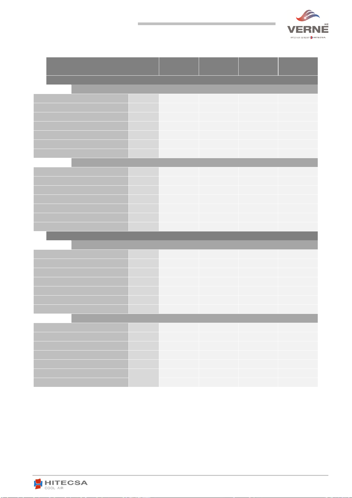
TECHNICAL SPECIFICATIONS
VERNE HE SERIE
251
351
401
501
REFRIGERANT
Type
R-410A
Global warming potential (GWP) (5)
2088
Refrigerant load WPHA
kg
0.7
0.8
0.8
2
Refrigerant load WPHBA
kg
1.7
1.8
2.8
3.8
COMPRESSOR
Type
Rotatory
Scroll
Quantity
1
Voltage
V / ~ / Hz
230/1/50
400/3/50
230/1/50
400/3/50
Oil type
ESTER VG74
PVE
PVE
PVE
Oil quantity in compressor
L
0.62
1.33
1.57
1.57
EVAPORATOR FAN
Type
Radial with EC motor
Quantity
1
Size
mm
310
310
310
400
Nominal air flow
m³/h
1500
2000
2300
2800
Static pressure available
Pa
25
37
50
50
Maximum pressure available
Pa
1050
1630
1580
1150
Motor nominal Capacity
kW
147
0,2
0,245
0,55
Nominal speed
r.p.m
1190
1558
1777
1044
Power supply
V / ~ / Hz
230/1/50
400/3/50
INDOOR HEAT EXCHANGER
Type
Coil with aluminium fins and copper pipes
Frontal area
m²
0.252
0.252
0.252
0.45
Fin spacing
mm - (")
1.8 - 3/8”
1.8 - ¾”
1.8 - 3/8”
2.1 - 3/8”
Oil type
PVE
PVE
PVE
POE
Oil quantity in compressor
L
1.57
2.46
2.46
3.31
OUTDOOR HEAT EXCHANGER
Type
Brazed plates
Quantity
1
Water connections (gas male screw)
"
¾”
1 1/4
Number of plates
42
42
42
32
ELECTRICAL DATA
Voltage
V / ~ / Hz
230/1/50-400/3/50
230/1/50-400/3/50
400/3+N/50
400/3+N/50
Maximum current input
A
17.4 -10.9
23.5 - 11.0
9.24
13.39
Start-up current
A
65.3- 31.0
92.0 - 52.84
62.04
73.79
DIMENSIONS AND WEIGHT
Length
mm
1135
1135
1135
1385
Width
mm
670
670
670
940
Height
mm
530
530
530
620
Conduit
mm x mm
350x350
350x350
350x350
450x500
Weight
kg
90
110
115
160
SOUND LEVEL
Sound pressure at 2 m
dB (A)
60
61
61
62
Total sound power (Lw)
dB (A)
76.5
77.5
78.0
78.5
5) GWP: Global warming potential (climatic) of 1 kg of greenhouse gas relative to 1 kg of CO2, calculated in terms of 100-year warming potential.
12
IOM_WPHBA HE-WPHA HE_091a1201_207815_180701_EN
HORIZONTAL WATER-AIR COMPACT PACKAGED UNITS
WPHA HE / WPHBA HE
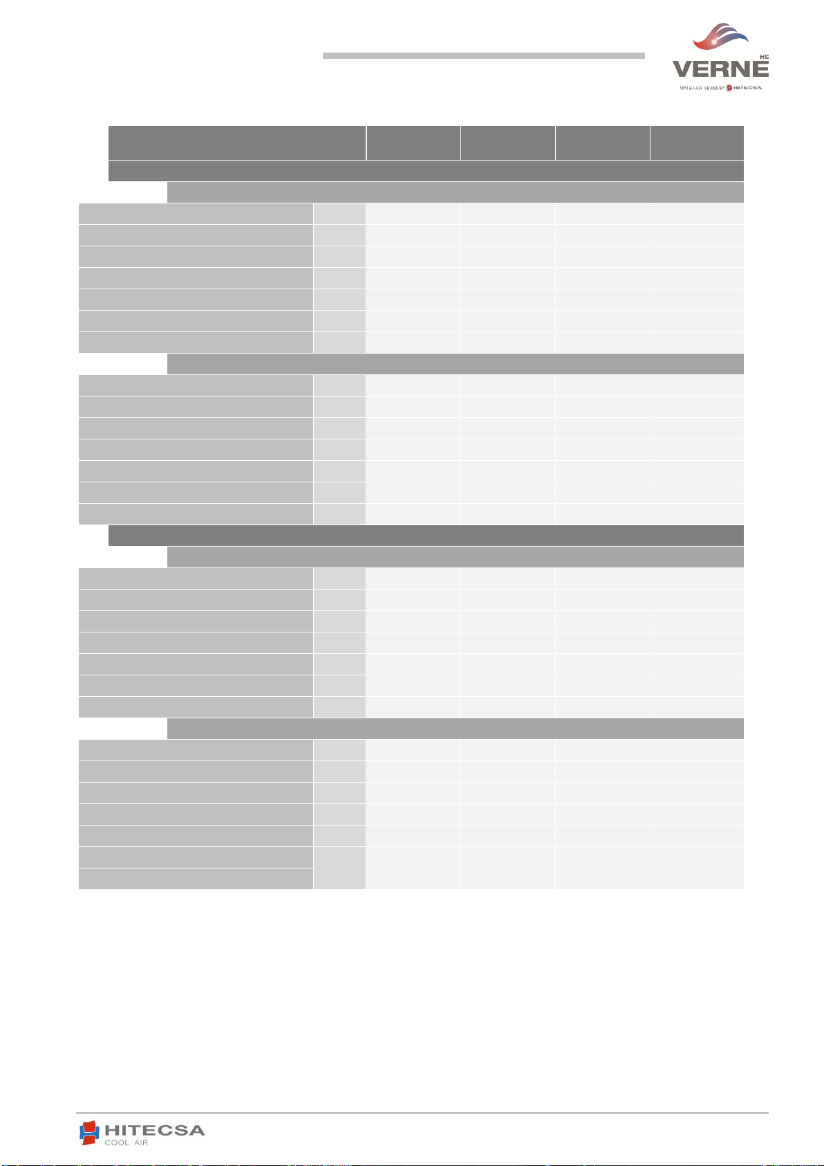
TECHNICAL SPECIFICATIONS
VERNE HE SERIE
701
751
1001
1201
WPHA
COOLING CAPACITIES (1)
Nominal cooling capacity (1)
kW
20.11
25.44
34.06
40.05
Power input (1)
kW
4.43
5.81
7.32
8.92
EER Coefficient (1)
kW / kW
4.54
4.38
4.66
4.49
SEER Coefficient (1)
kW / kW
4.27
4.05
4.28
4.11
ηs,c (1)
%
162.7
154
163
156.4
Water flow
m³/h
4.23
5.36
7.17
8.43
Differential pressure
kPa
30.3
46.9
34.4
46.5
COOLING CAPACITIES (2)
Nominal cooling capacity (2)
kW
22.46
28.44
38.09
44.8
Power input (2)
kW
3.2
4.18
5.42
6.39
EER Coefficient (2)
kW / kW
7.02
6.81
7.03
7.01
SEER Coefficient (2)
kW / kW
5.4
5.14
5.28
5.23
ηs,c (2)
%
208
197.7
203.3
201.1
Water flow
m³/h
4.73
5.99
8.02
9.43
Differential pressure
kPa
37.2
57.6
42.4
57.2
WPHBA (Heat pump units)
HEATING CAPACITIES (3)
Heating capacity (3)
kW
18.57
24.79
32.42
37.9
Power input Heat (3)
kW
3.96
5.63
7.27
8.59
COP Coefficient (3)
kW / kW
4.69
4.41
4.46
4.41
SCOP Coefficient (3)
kW / kW
4.07
3.82
3.86
3.81
ηs,h (3)
%
154.9
144.7
146.3
144.6
Water flow
m³/h
4.31
5.73
7.45
8.68
Differential pressure
kPa
31.3
53.1
37.0
49.0
HEATING CALORÍFICAS (4)
Heating capacity (4)
kW
14.51
19.4
25.41
29.73
Power input Heat (4)
kW
3.52
5
6.66
7.65
COP Coefficient (4)
kW / kW
4.13
3.88
3.82
3.89
SCOP Coefficient (4)
kW / kW
3.58
3.36
3.3
3.35
ηs,h (4)
%
135.1
126.2
123.9
126.1
Water flow
m³/h
3.4
4.53
5.97
7.04
Differential pressure
kPa
20.2
34.4
24.5
33.3
1) Nominal conditions. Refrigeration tower: Indoor air 27/19 ºC. Condenser water: inlet 30 ºC / outlet 35 ºC (Inlet
partial loads 26/22/18).
2) Geothermal conditions: Indoor air 27/19 ºC. Condenser water: inlet 10 ºC / outlet 15 ºC (Inlet partial loads
10/10/10).
3) Underground water conditions: Indoor air 20 ºC. Evaporator water: inlet 10 ºC, unit water flow 100 % outlet 7
ºC.
4) Brine conditions: Indoor air 20 ºC. Evaporator water: inlet 0 ºC, unit water flow 100 % outlet -3ºC.

13
IOM_WPHBA HE-WPHA HE_091a1201_207815_180701_EN
HORIZONTAL WATER-AIR COMPACT PACKAGED UNITS
WPHA HE / WPHBA HE
TECHNICAL SPECIFICATIONS
VERNE HE SERIE
701
751
1001
1201
REFRIGERANT
Type
R-410A
Global warming potential (GWP) (5)
2088
Refrigerant load WPHA
kg
1.6
1.7
2.4
3
Refrigerant load WPHBA
kg
4
4.2
6.1
6.3
COMPRESSOR
Type
Scroll
Quantity
1
Voltage
V / ~ / Hz
400/3/50
Oil type
PVE
PVE
PVE
POE
Oil quantity in compressor
L
1.57
2.46
2.46
3.31
EVAPORATOR FAN
Type
Radial with EC motor
Quantity
1
Size
mm
400
400
450
450
Nominal air flow
m³/h
3400
4300
6200
7000
Static pressure available
Pa
50
62
75
75
Maximum pressure available
Pa
1100
975
580
400
Motor nominal Capacity
W
2.4
2.4
2.0
2.0
Nominal speed
r.p.m.
1242
1509
1476
1643
Power supply
V / ~ / Hz
400/3/50
INDOOR HEAT EXCHANGER
Type
Coil with aluminium fins and copper pipes
Frontal area
m²
0.45
0.45
0.84
0.84
Fin spacing
mm - "
2.1 - 3/8”
OUTDOOR HEAT EXCHANGER
Type
Brazed plates
Quantity
1
Water connections (gas male screw)
"
1 ¼”
Number of plates
32
32
52
52
ELECTRICAL DATA
Voltage
V / ~ / Hz
400 / 3+N / 50
Maximum current input
A
17.89
19.64
23.01
26.12
Start-up current
A
90.79
128.74
128.51
150.42
DIMENSIONS AND WEIGHT
Length
mm
1385
1385
1930
1930
Width
mm
940
940
1040
1040
Height
mm
620
620
690
690
Conduit
mm x mm
450x500
450x500
550x550
550x550
Weight
kg
160
180
230
250
SOUND LEVEL
Sound pressure at 2 m
dB (A)
65
65
66
67
Total sound power (Lw)
dB (A)
81.5
82.0
82.5
83.5
5) GWP: Global warming potential (climatic) of 1 kg of greenhouse gas relative to 1 kg of CO2, calculated in terms
of 100-year warming potential.

14
IOM_WPHBA HE-WPHA HE_091a1201_207815_180701_EN
HORIZONTAL WATER-AIR COMPACT PACKAGED UNITS
WPHA HE / WPHBA HE
TRANSPORT & RECEPTION
INSPECTION AT RECEPTION
It is advisable to examine the equipment carefully at the time of its reception.
Check that the equipment has not been damaged during transport and has been supplied complete with all parts
specified in the order and/or with the optional specified in the order. If this is not the case contact the transport
company immediately. (First 48h)
Verify the correct voltage of the nameplate and make sure it is in accordance with local power supply.
In case of any flaw or anomaly detected, please contact HITECSA.
RIGGING
Before moving the unit, make sure that all panels are well fixed.
Raise and set down the equipment carefully.
Do not tilt the unit more than 15 degrees during transportation. (Fig. 1) (Fig. 2)
Always transport the unit in its original packaging to the place of installation.
All units come with a particular rigging diagram of that model, similar to the one shown below. Be sure to hoist
the machine through the points indicated in the diagram.
Make sure that the unit is balanced, stable and without any deformations when it is lifted.
STORAGE
If the equipment is going to be stored before the installation, please follow the instructions below in order to avoid damages,
corrosion or deterioration:
Move it carefully.
Do not place the machine in places exposed to ambient temperature above 50ºC and preferably keep the unit away
from direct sunlight.
Avoid placing the unit with plastic wrapping protection under the sun, as the pressure of the circuits could assume
values that could lead to the intervention of the safety valves.
- In addition, when cooling, water condensation occurs inside the machine and the plastic wrap.
Avoid placing other objects on top of the unit (unless it is done within the limits of the overlap planes indicated on the
packaging, etc. Follow these indications).
Avoid prolonged storage, before installation, water inlet, dust and objects in general due to invasion or biological,
meteorological and/or human inclemencies.
Minimum storage temperature: 5ºC.
Maximum relative humidity: 90%.
Fig. 1
Fig. 2
15
IOM_WPHBA HE-WPHA HE_091a1201_207815_180701_EN
HORIZONTAL WATER-AIR COMPACT PACKAGED UNITS
WPHA HE / WPHBA HE
INSTALLATION
INSTALLATION LOCATION
- Consult and respect the rules and local regulations which regulate the installation of air conditioning
systems.
- Choose a site without dust and debris.
- Respect the appropriate service area for the equipment which will be installed.
- Verify that the ground or structure on which the unit will be installed is able to support its weight in
operation.
- Fit shock absorbers throughout the installation to prevent the transmission of noise and vibration.
- Check that the direction of the sound level is not going to disturb anyone.
UNIT SETTLEMENT
Be sure unit is correctly balanced.
The bed frame should have sufficient strength to support unit weight.
Be sure that after settlement the unit drain is working properly.
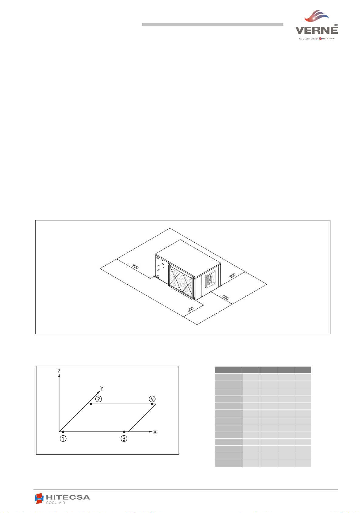
SERVICE AREA
Make sure to respect the following measurements for the correct operation of the unit.
WEIGHT DISTRIBUTION (kg)
MODEL
1
2
3
4
091
13
13
16
18
121
14
14
16
18
141
14
15
17
19
171
16
17
20
22
201
16
19
20
22
251
21
22
22
25
351
24
26
29
31
401
26
27
30
32
501
38
38
41
43
701
38
38
41
43
751
43
44
46
47
1001
55
56
59
60
1201
61
61
63
65
(3 –4): Electrical panelboard side

16
IOM_WPHBA HE-WPHA HE_091a1201_207815_180701_EN
HORIZONTAL WATER-AIR COMPACT PACKAGED UNITS
WPHA HE / WPHBA HE
INSTALLATION
DIMENSIONS AND WEIGHT
Models 091 –141
APROX. WEIGHT(Kg)
MODEL
Net Weight
Packaged Weight
091
60
75
121
62
77
141
65
80
Legend:
1. Power supply input
2. Water inlet
3. Outdoor water drain Ø 3/4” male
4. Water outlet
5. Air filter
6. Manoeuvre
7. Compressor
8. EC fan
9. Condenser heat exchanger
10. Evaporator coil
11. Presostatic valve connection (option)
AA Access panel

17
IOM_WPHBA HE-WPHA HE_091a1201_207815_180701_EN
HORIZONTAL WATER-AIR COMPACT PACKAGED UNITS
WPHA HE / WPHBA HE
INSTALLATION
DIMENSIONS AND WEIGHT
Models 171 –201
APROX. WEIGHT (Kg)
MODEL
Net Weight
Packaged Weight
171
75
90
201
77
92
Legend:
1. Power supply input
2. Water inlet
3. Outdoor water drain Ø 3/4” male
4. Water outlet
5. Air filter
6. Manoeuvre
7. Compressor
8. EC fan
9. Condenser heat exchanger
10. Evaporator coil
11. Presostatic valve connection (optional)
AA Access panel

18
IOM_WPHBA HE-WPHA HE_091a1201_207815_180701_EN
HORIZONTAL WATER-AIR COMPACT PACKAGED UNITS
WPHA HE / WPHBA HE
INSTALLATION
DIMENSIONS AND WEIGHT
Models 251 –451
APROX. WEIGHT (Kg)
MODEL
Net Weight
Packaged Weight
251
90
105
351
110
115
401
115
130
Legend:
1. Power supply input
2. Water inlet
3. Outdoor water drain Ø 3/4” male
4. Water outlet
5. Air filter
6. Manoeuvre
7. Compressor
8. EC fan
9. Condenser heat exchanger
10. Evaporator coil
11. Presostatic valve connection (optional)
12. Main switch
AA Access panel

19
IOM_WPHBA HE-WPHA HE_091a1201_207815_180701_EN
HORIZONTAL WATER-AIR COMPACT PACKAGED UNITS
WPHA HE / WPHBA HE
INSTALLATION
DIMENSIONS AND WEIGHT
Models 501 –751
APROX. WEIGHT (Kg)
MODEL
Net Weight
Packaged Weight
501
160
175
701
160
175
751
180
195
Legend:
1. Power supply input
2. Water inlet
3. Outdoor water drain Ø 3/4” male
4. Water outlet
5. Air filter
6. Manoeuvre
7. Compressor
8. EC fan
9. Condenser heat exchanger
10. Evaporator coil
11. Presostatic valve connection (optional)
12. Main switch
AA Access panel

20
IOM_WPHBA HE-WPHA HE_091a1201_207815_180701_EN
HORIZONTAL WATER-AIR COMPACT PACKAGED UNITS
WPHA HE / WPHBA HE
INSTALLATION
DIMENSIONS AND WEIGHT
Models 1001 –1201
APROX. WEIGHT (Kg)
MODEL
Net Weight
Packaged Weight
1001
230
245
1201
250
265
Legend:
1. Power supply input
2. Water inlet
3. Outdoor water drain Ø 3/4” male
4. Water outlet
5. Air filter
6. Manoeuvre
7. Compressor
8. EC fan
9. Condenser heat exchanger
10. Evaporator coil
11. Presostatic valve connection (optional)
12. Main switch
AA Access panel
This manual suits for next models
55
Table of contents
Other Hitecsa Air Conditioner manuals

Hitecsa
Hitecsa VERNE WPHBA Series User manual

Hitecsa
Hitecsa WCHZ 201 User manual

Hitecsa
Hitecsa ECV-SP 1001 User manual

Hitecsa
Hitecsa DXCZ 171 Manual

Hitecsa
Hitecsa FPW 20 Owner's manual

Hitecsa
Hitecsa WCVZ Series Owner's manual

Hitecsa
Hitecsa ECVBZ Series Manual

Hitecsa
Hitecsa WCHZ Series Owner's manual

Hitecsa
Hitecsa KUBIC RMXRBA HE Series User manual

Hitecsa
Hitecsa ACHIA 601 Installation and operating instructions


