Hitecsa KUBIC RMXRBA HE Series User manual

IOM_RMXRBA HE_40.3a219.4_207816_200308_EN
INSTALLATION, OPERATION AND MAINTENANCE MANUAL
Heat Pump
RMXRBA HE
ROOF TOP UNITS –AXIAL FANS
Models: 40.3 │ 45.3 │ 57.3 │ 71.3 │ 77.3
102.3 │ 114.2 │ 125.2 │ 135.2 │ 171.4 │ 200.4 │ 219.4
Cooling capacities: from 39.5 kW to 218.5 kW
Heating capacities:
from 42.4 kW to 226.7 kW

2
IOM_RMXRBA HE_40.3a200.4_207816_200308_EN
ROOF TOP UNITS –AXIAL FANS
RMXRBA HE
Thank you for trusting the Hitecsa Products. Our company has been offering the market an extended range of specialized
equipment for air conditioning and cooling installations for over 35 years. Our approach is based on efficiency, flexibility and on
practical solutions. This has been the hallmark of our product catalogue.
The versatility of our factory allows us to deliver solutions that can meet any requirement and we endeavour solving any problem
that may arise in designing and implementing air conditioning installations.
From all of us at Hiplus Aire Acondicionado, once again, thank you very much.

3
IOM_RMXRBA HE_40.3a200.4_207816_200308_EN
ROOF TOP UNITS –AXIAL FANS
RMXRBA HE
RMXRBA HE
INDEX
INTRODUCTION ......................................................................................................................................................... 6
Name plate.......................................................................................................................................................... 8
REGULATIONS AND CERTIFICATIONS.................................................................................................................. 9
SAFETY INSTRUCTIONS........................................................................................................................................ 10
TECHNICAL SPECIFICATIONS.............................................................................................................................. 12
Models 40.3 –77.3............................................................................................................................................ 12
RMXRBA HE 40.3-77.3 RCF / VRC modules...................................................................................................... 14
RMXRBA HE 102.3-219.4..................................................................................................................................... 15
RMXRBA HE 102.3-219.4 RCF / VRC.................................................................................................................. 17
OPERATION LIMITS ............................................................................................................................................... 18
COOLING MODE.................................................................................................................................................. 18
.............................................................................................................................................................................. 18
HEATING MODE.................................................................................................................................................. 18
TRANSPORT & RECEPTION.................................................................................................................................. 19
INSPECTION AT RECEPTION............................................................................................................................. 19
RIGGING .............................................................................................................................................................. 19
STORAGE ............................................................................................................................................................ 19
DIMENSIONS AND WEIGHT................................................................................................................................... 20
WEIGHT OF STANDARD MODELS..................................................................................................................... 20
WEIGHT OF UNITS WITH RCF MODULE........................................................................................................... 20
WEIGHT OF UNITS WITH VRC MODULE........................................................................................................... 20
DIMENSIONS....................................................................................................................................................... 21
Models 40.3 –77.3............................................................................................................................................ 21
Models 102.3 - 114.2........................................................................................................................................ 23
Models 102.3 - 114.2 RCF and VRC............................................................................................................... 24
Models 125.2 and 135.2 ....................................................................................................................................... 25
Models 125.2 and 135.2 RCF and VRC................................................................................................................ 26
Models from 171.4 to 219.4 .................................................................................................................................. 27
Models from 171.4 to 219.4 RCF and VRC.......................................................................................................... 28
INSTALLATION ....................................................................................................................................................... 29
REFRIGERATION DIAGRAMS ............................................................................................................................ 29
MODELS 114.2 –135.2 .................................................................................................................................... 30
Models from 171.4 to 219.4 .................................................................................................................................. 31
INSTALLATION LOCATION................................................................................................................................. 32
UNIT SETTLEMENT............................................................................................................................................. 32

4
IOM_RMXRBA HE_40.3a200.4_207816_200308_EN
ROOF TOP UNITS –AXIAL FANS
RMXRBA HE
SERVICE AREA ................................................................................................................................................... 32
MODELS 40.3 –77.3........................................................................................................................................ 32
MODELS 102.3 –114.2 .................................................................................................................................... 32
MODELS from 125.2 to 135.2........................................................................................................................... 33
MODELS from 171.4 to 219.4........................................................................................................................... 33
MODELS from 40.3 to 77.3 with RCF ............................................................................................................... 34
MODELS 102.3-114.2 with RCF ....................................................................................................................... 34
MODELS 125.2 - 135.2 with RCF ..................................................................................................................... 35
MODELS from171.4 to 219.4 with RCF............................................................................................................. 35
WATER DRAIN..................................................................................................................................................... 36
Drainage –internal side..................................................................................................................................... 36
Drainage –external side.................................................................................................................................... 36
AIR DUCTS........................................................................................................................................................... 36
Assembly types................................................................................................................................................. 37
Assembly types for units with RCF module....................................................................................................... 38
ELECTRICAL INSTALLATION ............................................................................................................................. 39
ELECTRICAL DATA ............................................................................................................................................. 39
ELECTRICAL CONNECTION DIAGRAM............................................................................................................. 39
INSTALLATION .................................................................................................................................................... 40
TH-Tune control connection (PGD or Mini-pGD optional) ............................................................................... 40
pLan network connection (communication between some units). ..................................................................... 40
INSTALLATION .................................................................................................................................................... 41
TCONN bypass device connection.................................................................................................................... 41
Remote connection ........................................................................................................................................... 41
OPERATION............................................................................................................................................................ 42
BEFORE START-UP ............................................................................................................................................ 42
START UP............................................................................................................................................................ 42
INDOOR CENTRIFUGAL FAN TRANSMISSION ADJUSTMENT (optional)........................................................ 43
TH TUNE CONTROL............................................................................................................................................ 44
Screen............................................................................................................................................................... 44
Start / Stop....................................................................................................................................................... 44
Temperature Adjustment................................................................................................................................ 44
Calibration of the probe of indoor temperature of Th-Tune ........................................................................ 44
System Operating Modes.................................................................................................................................. 44
Indoor Fan Modes: ............................................................................................................................................ 44
Time Schedule .................................................................................................................................................. 45
Alarms............................................................................................................................................................... 46
PGD or Mini pGD THERMOSTAT ........................................................................................................................ 47
KEYBOARD ...................................................................................................................................................... 47
On/Off................................................................................................................................................................ 47
Temperature adjustment ................................................................................................................................... 47
System operating modes change...................................................................................................................... 47
Clock adjustment............................................................................................................................................... 48
Time schedule................................................................................................................................................... 48
Local Network.................................................................................................................................................... 49
Alarms............................................................................................................................................................... 50
DIAGNOSIS OF THE ALARMS............................................................................................................................ 51

5
IOM_RMXRBA HE_40.3a200.4_207816_200308_EN
ROOF TOP UNITS –AXIAL FANS
RMXRBA HE
MAINTENANCE....................................................................................................................................................... 54
CONSERVATION AND CLEANING ..................................................................................................................... 54
INDOOR FANS WITH EC MOTOR....................................................................................................................... 56
Diagnosis / Faults............................................................................................................................................ 56
Status Out with flash code ............................................................................................................................. 57
OUTDOOR FANS WITH PKDM / PKDT............................................................................................................... 58
Led of internal state, diagnosis through flash codes................................................................................... 58
REPAIRING OPERATIONS.................................................................................................................................. 60
REFRIGERANT CHARGE.................................................................................................................................... 60
OPTIONS ................................................................................................................................................................. 61
APPENDIX: SAFETY DATA R-410A....................................................................................................................... 63
6
IOM_RMXRBA HE_40.3a200.4_207816_200308_EN
ROOF TOP UNITS –AXIAL FANS
RMXRBA HE
INTRODUCTION
Purpose of this Manual
The present manual together with any other technical document such as refrigeration or
hydraulic lines drawings and electrical diagrams among others have been issued to provide the
necessary information for installation, start-up and maintenance of the unit. Therefore it is
essential to read the instructions very carefully. Please contact us if your machine is equipped
with an option or any special modification that are not mentioned in the present manual.
Make sure that all the necessary information for the correct installation of the system is included
in the manuals that have been supplied together with this unit and/or the rest of the indoor units,
accessories, etc. The manufacturer declines any responsibility in case of people/animals injuries
or material damages resulting from an incorrect use of the unitand/or non-compliance with these
instructions.
In case of different interpretations and/or errors, the priority order of validity of the given
documents will be: 1. Name plate of the unit stating the specifications. 2. IOM (the present
document), 3. EDM, technical catalogue, 4. UM user manuals.
Storage of the Manual
This manual and the electrical diagram of the unit must be preserved and remain available to the operator for any
further consultation.
Updating the Data
The continuous improvement in design and performance to which we are committed to gives us the right to modify
the specifications of our products without prior notice.
Electrical Supply
Check that the electrical network features comply with the data shown in the data nameplate of the
unit.
Local Safety Regulations
Observe and analyse all the possible causes of accidents that may arise in the place or places of installation of the
units, check all the medium and the tools that will be used, etc. It is not possible to anticipate each one of the potential
circumstances of danger in this manual. Respect the valid local security standards during installation.
Principles of Security
The unit has been designed and built so that it does not represent any risk to the health and safety of people.
Appropriate solutions for the project have been planned to eliminate the possible causes of risk during installation.
Installation
Please read carefully the present document. Any damage to the equipment caused by an incorrect
installation will not be covered by the insurance. Any installation operation shall be completed according
to the instructions of the manufacturer and carried out by certified personnel. This document has been
issued for installers, however, should you find the instructions not clear enough, please do not hesitate
to contact us.
Reminder: all operations shall be completed according to the local security regulations.
7
IOM_RMXRBA HE_40.3a200.4_207816_200308_EN
ROOF TOP UNITS –AXIAL FANS
RMXRBA HE
INTRODUCTION
Utilization
The unit will be used only for the purpose it has been designed for. Any other use does not imply any kind of liability
or responsibility from the manufacturer.
Incorrect Operation
In case of breakdowns or operation faults, turn the unit off.
Periodic Inspections and Maintenance
Carry out periodic inspections to detect possible damaged or broken parts. If these parts are not
repaired, people injuries or material damages could be caused. Disconnect the power supply of the
unit before carrying out any maintenance operation.
Make sure that the maintenance areas are accessible. If these areas have to be invaded bythe lateral
air supply and/or return ducts, verify that the design of the ducts allows the access to the fans and
that they are not a hindrance when replacing the filters. If that is not possible make sure access is
possible from the other side.
All operations shall be carried out in accordance with the local safety regulations.
Repairing Operations
The reparations shall always and exclusively be completed by trained personnel previously authorized
by the manufacturer and only original spares shall be used. The safety devices of the unit may be
damaged in case of non-compliance with these warnings.
Modifications
The manufacturer will not respond to possible warranty claims and damages of the unit in case of electrical and/or
mechanical modifications. The unauthorized manipulation, reparation or modification of the unit will automatically
invalidate the warranty.
Packaging and Replacement of Equipment
The material of the package (plastic bags, insulating materials, nails, etc.) is a potential source of
danger. Consequently, it should be kept out of the reach of children and properly recycled according
to the valid local safety regulations.
Do not mix this product with household waste at the end of its life. Due to the refrigerant, oil and other
components contained in this product, it must be dismantled by professional installers. All the
waste, depending on its nature shall be sent to recycling, composting or treatment plants, or to an
authorized management agency in accordance with the current local legislations.
Refrigerant
This product is hermetically sealed and contains R-410A which is a HFC fluorinated greenhouse gas.
8
IOM_RMXRBA HE_40.3a200.4_207816_200308_EN
ROOF TOP UNITS –AXIAL FANS
RMXRBA HE
INTRODUCTION
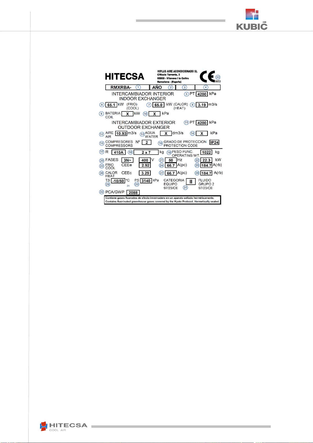
Name plate
Description of the name plate placed on the unit.
1. Name of the unit.
2. Production year
3. Unit code.
4. Serial number.
5. Test Pressure, Refrigerant Side.
6. Cooling capacity in rated conditions (EN-14511)
7. Heating capacity in rated conditions (EN-14511)
8. Fluid flow indoor heat exchanger (air).
9. Capacity of support coils or heating (if any)
10. Maximum operating pressure of the support coil if
applicable (“X” if not applicable).
11. Maximum operating pressure outdoor heat exchanger
refrigerant side.
12. Air flow in the outdoor heat exchanger.
13. Water flow in the outdoor heat exchanger (“X” if not
applicable).
14. Maximum operating pressure outdoor heat exchanger
water side (“X” if not applicable).
15. Number of compressors.
16. Protection code IP (Dust/water tightness).
17. Type of refrigerant needed for unit operation.
18. Basic load of the unit. In case of difference with
catalogue value, the indicated value of the nameplate is
the most appropriate for this unit in particular (E.g. “2 x
7” == “7 + 7“ means a charge of 7 kg per circuit)
19. Total weight of the unit + optional and accessories in
operating conditions.
20. Number of phases (three-phase ±N, single phase, etc.)
and voltage at which this unit must be supplied.
21. Frequency of the electrical network to which the machine
must be connected.
22. Power input of the machine (standard unit operating
under rated cold conditions ± optional, etc.)
23. Gross performance of the unit (+ optional and
accessories) in the heating mode.
24. Maximum current operating in the cooling mode.
25. Maximum starting current (all electrical components
running at maximum current and commissioning stage of
compressors).
26. Gross performance of the unit (+ optional and
accessories) in heating mode.
27. Maximum current operating in cooling mode.
28. Maximum starting current (all electrical components
running at maximum current and largest compressor in
blocked rotor).
29. Maximum TS allowed lower/higher design temperature,
according to pressure equipment directive 2014/68/UE
(PED).
30. Maximum PS allowed design pressure (PED).
31. Unit category (PED) and fluid group (refrigerant)
32. Global warming potential of refrigerant relative to CO2.
33. CE label and number of the certifying entity (only
category II or over).

9
IOM_RMXRBA HE_40.3a200.4_207816_200308_EN
ROOF TOP UNITS –AXIAL FANS
RMXRBA HE
REGULATIONS AND CERTIFICATIONS
ISO 9001 CERTIFICATION: HIPLUS AIRE ACONDICIONADO S.L., by endeavouring to always gain the maximum
satisfaction from their customers, obtained the ISO 9001: Quality System for our design and production activities. That
result shows our continuous determination to improve quality and the reliability of all our products. Our commercial
activities, design, raw materials, production processes and after-sales service represent the means to reach our goal.
CE MARKING: Our products are CE marked according to the essential requirements of the applicable EC directives and
their last modifications and comply with the national legislation of each country.
EUROVENT CERTIFICATION: HITECSA participates in the EUROVENT Certification program. Please check which
models are certified on the web.
10
IOM_RMXRBA HE_40.3a200.4_207816_200308_EN
ROOF TOP UNITS –AXIAL FANS
RMXRBA HE
SAFETY INSTRUCTIONS
Before starting any installation, service or maintenance operation, turn the main power
switch off in order to avoid electrical discharges that may cause personal injuries.
Do not touch or adjust the safety devices inside the unit. For repairs use only original spare parts and install them
properly in the same position where the old parts were fitted.
The installation and maintenance of air conditioning equipment may be dangerous due to the pressure of the system,
the high temperature of some of its parts and the electrical components.
Do not install the unit in an explosive atmosphere.
It is absolutely forbidden to carry out work on electrical live parts. The protection class of the opened unit is IP00!
Check the safe isolation from the supply by using a two-pole voltage detector.
Even after disconnecting the main voltage, life-threatening charges may appear between the protective ground “PE” and
the main connection.
If the motor of the fan runs independently after the unit has been switched off because it is pushed by airflowfor example,
dangerous voltage of more than 50 V may be present in some of the internal connection parts of the motor. In that case
the fan is working as a generator.
When the unit is equipped with EC motors or motors with variable speed control, the ground wire (depending on the
switching frequency, the current source voltage and the motor capacity) is conducting high discharge currents. Therefore
check that the earth grounding is complying with the EN standards even for testing and trial operations (EN 50 178, Art.
5.2.11). Without grounding dangerous voltages may be present in the motor housing.
The use of capacitors implies a danger of death even after switching the device off in case of direct contact with
conductive parts or with parts that carry voltage due to fault conditions. Removing or opening the housing of the controller
and the terminal box for example is only permitted after the power supply cable has been disconnected for 3 minutes.
DANGER

11
IOM_RMXRBA HE_40.3a200.4_207816_200308_EN
ROOF TOP UNITS –AXIAL FANS
RMXRBA HE
SAFETY INSTRUCTIONS
Only qualified and trained service staff (technical service) is authorized to carry out installation, commissioning and
maintenance. Unqualified personnel will carry out basic tasks only such as cleaning and replacement of filters, or filter
cleaning (excluding the refrigerant filters), etc…
Prevent access to children to avoid that they play with the equipment.
For all visits, follow carefully all recommended precautions: the instructions recommended in the installation, operation
and maintenance manual, as well as the precautions stated on the stickers placed on the unit. Do not forget to strictly
follow any other legal safety instructions.
DO NOT introduce objects into the air inlets or outlets that might be drawn into the fan, people, etc.
Never approach the fan until it has stopped completely! Beware as it may be rotating even without electric power but
airflow for example.
The fan / motor may start and stop automatically due to functional reasons.
After a power failure or a main disconnection an automatic restart of the fan takes place when power supply returns!
The external rotor rotates during operation (for external rotor motors).
Use safety glasses, work gloves and any other safety accessory that may be necessary for the operation.
For brazing operations use a quenching cloth and make sure you have a fire extinguisher close to you.
This product contains fluorinated greenhouse gases. In case of leakage air may be displaced which may cause lack of
oxygen.
The decomposition of fluorinated gases when being burned during brazing operations for example may cause the
presence of highly toxic and corrosive gases.
Please follow all the safety recommendations carefully.
ATTENTION!
The responsibility for all personal and material damages caused by an unexpected or inappropriate use
will be born by the person or the operating company of the unit and not by the manufacturer.
WARNING!
12
IOM_RMXRBA HE_40.3a200.4_207816_200308_EN
ROOF TOP UNITS –AXIAL FANS
RMXRBA HE
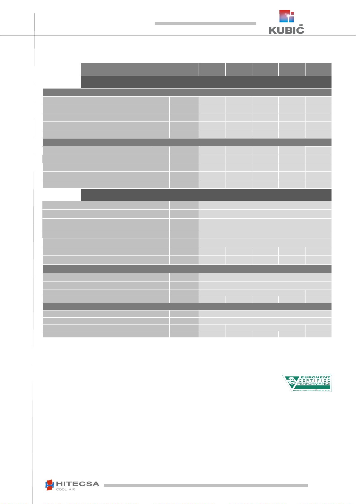
TECHNICAL SPECIFICATIONS
Models 40.3 –77.3
KUBIC HE range
40.3
45.3
57.3
71.3
77.3
CAPACITIES
COOLING MODE (1)
Cooling capacity
kW
39.5
45.2
57.2
71
76.9
Power input
kW
16.4
18.7
23.7
29.4
31.9
EER Coefficient
kW/ kW
2.41
2.41
2.41
2.41
2.41
SEER Seasonal coefficient
kW/ kW
3.41
3.33
3.27
3.14
3.14
Seasonal performance
ηs,c
%
133.5
130.3
127.6
122.4
122.4
HEATING MODE (2)
Heat capacity
kW
42.4
49.3
58.2
76
83.7
Power input
kW
12.4
14.5
18.1
25.2
27.8
COP Coefficient
kW/ kW
3.41
3.41
3.21
3.01
3.01
SCOP Coefficient
kW/ kW
2.99
2.95
2.97
2.95
2.95
Seasonal performance
ηs,h
%
116.4
115.1
115.9
115.1
115.1
REFRIGERATION CIRCUIT
Refrigerant type
-
R-410A
Compressor type
-
Scroll
Number of refrigeration circuits
-
2
Power stages
-
4
GWP (3)
-
2088
Total charge of refrigerant
kg
11
11.7
14
16.5
17.7
Environmental impact (CO2 eq.)
Tn (CO2)
26.52
28.61
32.78
34.87
36.96
REFRIGERATION CIRCUIT nº 1.
Number of compressors
-
2
Oil type
-
PVE - FV68S
Oil volume
litre
3.14
6
Refrigerant charge
kg
5.5
5.7
6.5
8.5
8.2
REFRIGERATION CIRCUIT Nº 2.
Number of compressors
-
1
Oil type
-
POE- 160SZ
Oil volume
litre
3
3.3
3.6
Refrigerant charge
kg
5.5
6
7.5
8
9.5
(1) Calculated according to the UNE-EN-14511 standard for indoor temperature conditions of 27ºC B.S. / 19°C B.H. and 35ºC of outdoor temperature.
(2) Calculated according to the UNE-EN-14511 standard for indoor temperature conditions of 20ºC and 7°C B.S. / 6ºC B.H of outdoor temperature.
(3) Global Warming Potential (climatic) of 1 kg of greenhouse gas relative to 1 kg of CO2, calculated in terms of 100-year warming potential.

13
IOM_RMXRBA HE_40.3a200.4_207816_200308_EN
ROOF TOP UNITS –AXIAL FANS
RMXRBA HE
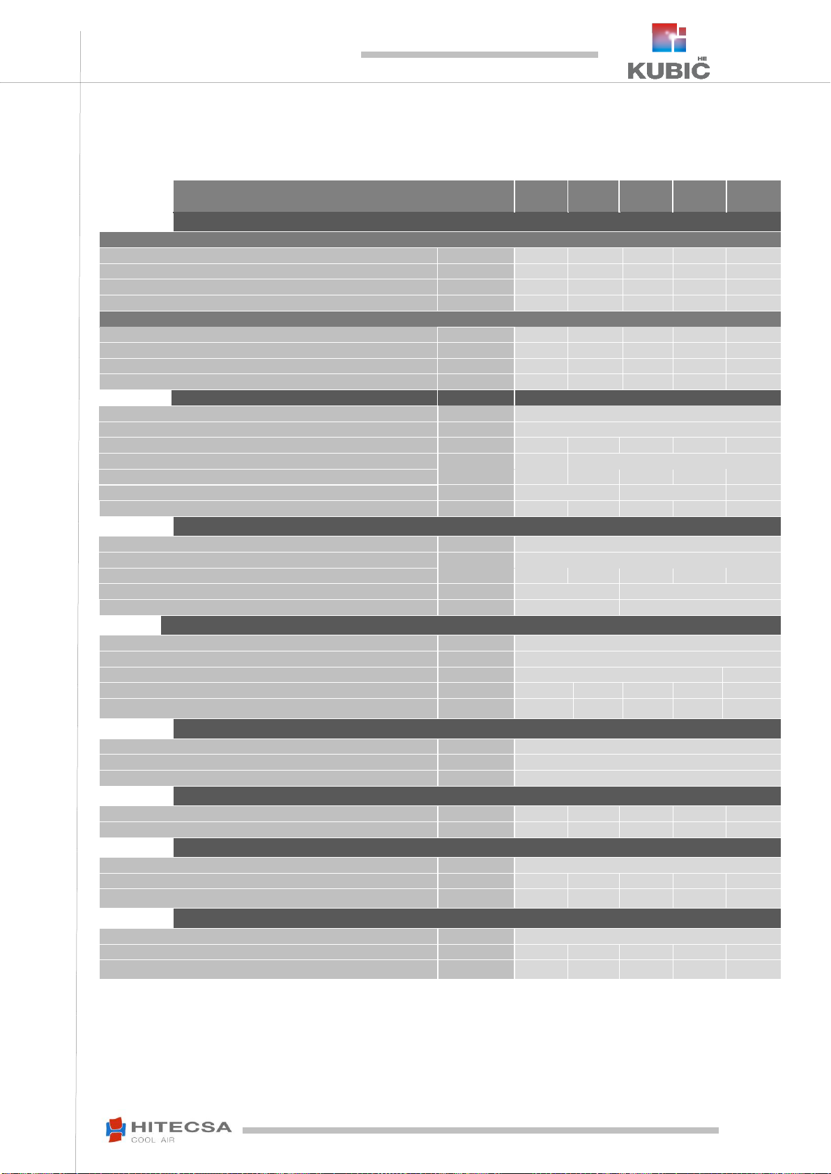
TECHNICAL SPECIFICATIONS
RMXRBA 40.3-77.3
KUBIC HE range
40.3
45.3
57.3
71.3
77.3
OUTDOOR FAN
Type
-
Axial Fan –Aluminium-copper Coil
Quantity
-
2
Maximum air flow
m³/h
27200
32800
Available pressure
Pa
0
Maximum Power input
kW
2x1.25
2x2.06
Maximum absorbed Current
A
2x 3
2x3.8
INDOOR RADIAL FAN
Type
-
Radial EC
Quantity
-
2
Nominal air flow
m³/h
9000
10200
11500
14000
15500
Standard available pressure
Pa
150
200
Total Power input
kW
1.87
2.69
1.95
3.06
4.01
Nominal power
kW
2x 2.5
2x 2.4
2x 3.3
Maximum operating current (unit)
A
2x 3.84
2x 3.74
2x 5.16
Maximum available pressure
Pa
750
600
750
400
550
DIMENSIONS
Length
mm
2910
Width
mm
2220
Height
mm
1300
Connexion diameter –condensate water drain
Ø
3/4" Gas
WEIGHT
Heat pump net weight
kg
1080
1087
1155
1169
1217
ELECTRICAL DATA
Power supply
V /~ /Hz
400V / 3ph + N / 50Hz
Maximum absorbed current
A
51
57
66
78
93
Start current
A
141
189
195
221
271
SOUND POWER LEVEL (Lw)
Surround standard unit
dBA
86.0
86.3
85.9
87.2
88.3
Surround Unit working at 50% (4)
dBA
81.9
81.5
82.2
83.8
85.0
Surround Unit with compressor cover
dBA
85.6
85.8
85.3
86.7
87.6
Surround Unit at 50% (4) and compressor cover
dBA
81.3
81.6
81.2
83.0
84.0
(4) Unit working with the fan at speed 2 and with 50% capacity.
14
IOM_RMXRBA HE_40.3a200.4_207816_200308_EN
ROOF TOP UNITS –AXIAL FANS
RMXRBA HE
TECHNICAL SPECIFICATIONS
RMXRBA HE 40.3-77.3 RCF / VRC modules
KUBIC HE RCF / VRC range
40.3
45.3
57.3
71.3
77.3
NOMINAL CAPACITIES
COOLING MODE (5)
Cooling capacity RCF
kW
52.53
60.11
76.07
94.42
102.27
Total absorbed Power RCF
kW
18.69
21.31
27.01
33.51
36.36
Cooling capacity VRC
kW
41.91
47.96
60.69
75.33
81.59
Total absorbed Power VRC
kW
17.25
20.21
24.72
31.71
35.27
HEATING MODE (6)
Heating capacity RCF
kW
51.03
59.33
70.04
91.47
100.73
Total absorbed Power RCF
kW
16.09
18.71
23.46
32.67
35.98
Heating capacity VRC
kW
44.48
51.91
61.02
80.04
88.46
Total absorbed Power VRC
kW
14.34
17.18
20.69
29.47
33.25
SUPPLY FAN
Type
-
Radial EC
Quantity
-
2
Nominal air flow
m³/h
9000
10200
11500
14000
15500
Standard available pressure
Pa
150
200
Total Power input
kW
1.87
2.69
1.95
3,06
4,01
Nominal power
kW
2x 2.5
2x 2.4
2x 3.3
Max. available pressure
Pa
750
600
750
400
550
RETURN FAN
Type
-
Radial EC
Quantity
-
2
Nominal air flow
m³/h
9000
10200
11500
14000
15500
Standard available pressure
Pa
75
100
Max. operation current
A
2 x 3.84
2 x 5.96
REFRIGERANT CIRCUIT RCF module
Quantity of compressors
-
1
Oil type
-
PVE - FV68S
Oil volume
litre
1,7
1,6
Refrigerant charge
kg
3,0
3,0
3,2
3,3
3,3
Environmental impact (CO2 eq.)
Tn (CO2)
6,26
6,26
6,68
6,89
6,89
DIMENSIONS
Length
mm
3980
Width
mm
2235
Height
mm
1300
WEIGHT
RCF models
kg
1460
1467
1557
1571
1677
VRC models
kg
1380
1387
1455
1469
1517
ELECTRICAL DATA units with RCF module
Power supply
V /~ /Hz
400V / 3ph + N / 50Hz
Maximum absorbed current
A
69
75
90
103
124
Start current
A
159
207
219
245
302
ELECTRICAL DATA units with VRC module
Power supply
V /~ /Hz
400V / 3ph + N / 50Hz
Maximum absorbed current
A
59
65
78
90
105
Start current
A
149
197
207
233
283
5) Calculated with 50% of fresh air and for indoor temperature conditions of 27ºC / 50%HR. y 35ºC / 50% of outdoor temperature.
6) Calculated with 50% of fresh air and for indoor temperature conditions of 20ºC y 10°C B.S. / 6ºC B.H. of outdoor temperature.
15
IOM_RMXRBA HE_40.3a200.4_207816_200308_EN
ROOF TOP UNITS –AXIAL FANS
RMXRBA HE
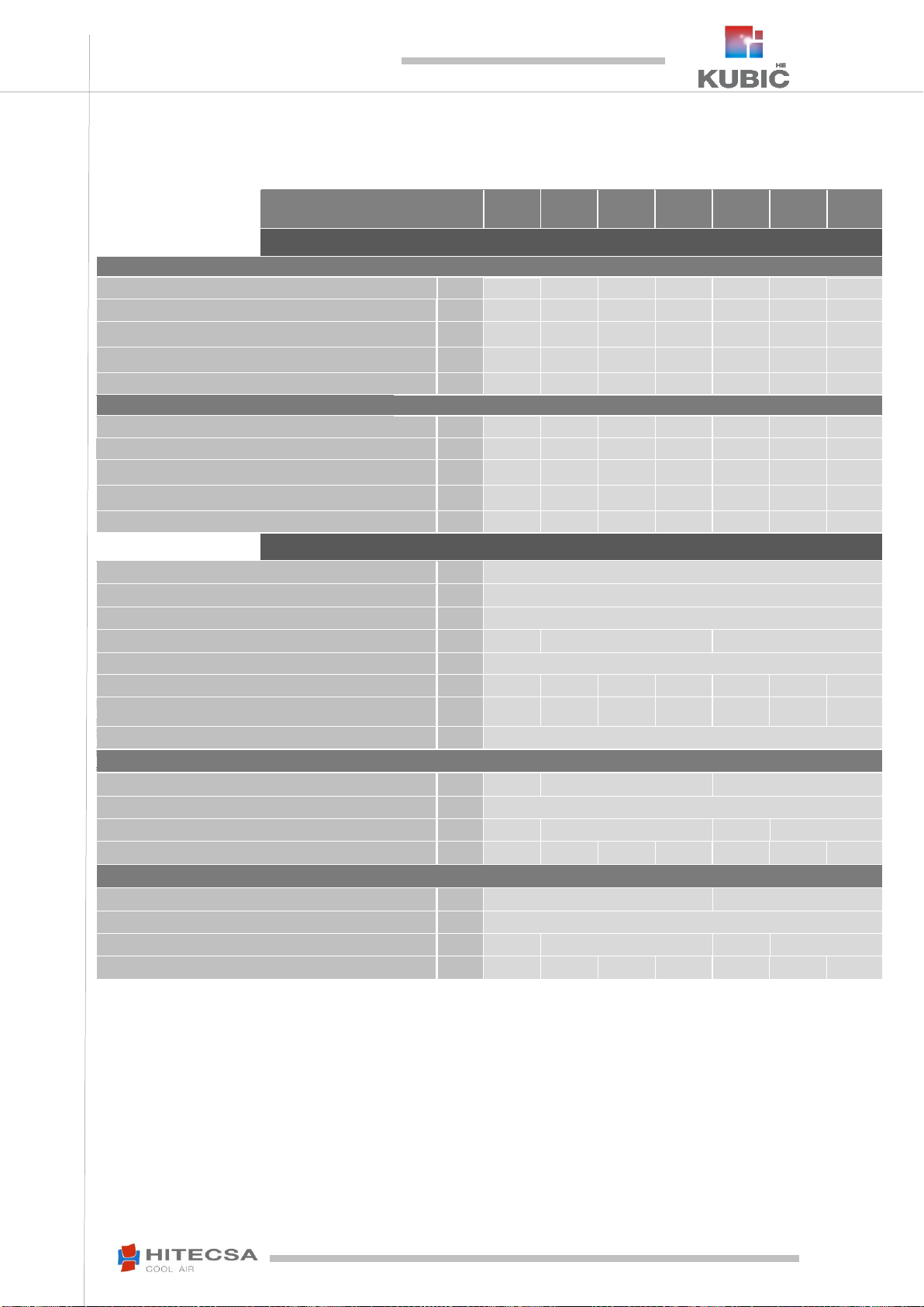
TECHNICAL SPECIFICATIONS
RMXRBA HE 102.3-219.4
KUBIC HE range
102.3
114.2
125.2
135.2
171.4
200.4
219.4
CAPACITIES
COOLING MODE (1)
Cooling capacity
kW
101.5
113.6
125.3
134.8
171
200
218.5
Power input
kW
32.7
39.5
44.4
49.9
53.9
69.1
77.8
EER Coefficient
kW/
kW
3.11
2.88
2.82
2.70
3.17
2.89
2.81
SEER Seasonal coefficient
kW/
kW
4.01
3.30
3.20
3.01
4.18
3.59
3.49
Seasonal performance
ηs,c
%
157.5
128.8
125.0
117.5
164.2
140.4
136.6
HEATING MODE (2)
Heat capacity
kW
100.8
119.1
132.7
143
169.8
205.7
226.7
Power input
kW
29.5
35.6
41.4
45.8
49.8
63.3
70.6
COP Coefficient
kW/
kW
3.41
3.35
3.21
3.12
3.41
3.25
3.21
SCOP Coefficient
kW/
kW
3.23
3.01
2.98
2.96
3.12
3.00
2.96
Seasonal performance
ηs,h
%
126.0
117.2
116.1
115.4
121.7
117.1
115.5
REFRIGERATION CIRCUIT
Refrigerant type
-
R-410A
Compressor type
-
Scroll
Number of refrigeration circuits
-
2
Power stages
-
4
2
4
GWP (3)
-
2088
Total charge of refrigerant
kg
28.5
28
28
33.0
48.0
54.0
56.0
Environmental impact (CO2 eq.)
Tn
(CO2)
59.5
58.5
58.5
68.9
100.2
112.8
116.9
Condensate water drain connection
Ø
3/4" Gas
REFRIGERATION CIRCUIT Nº 1.
Number of compressors
-
2
1
2
Oil type
-
POE oil
Oil volume
litre
6.6
6.7
6.9
13.4
Refrigerant charge
kg
15
14
14
14.5
24.0
27.0
28.0
REFRIGERATION CIRCUIT Nº 2.
Number of compressors
-
1
2
Oil type
-
POE oil
Oil volume
litre
3.6
6.7
6.9
13.4
Refrigerant charge
kg
13,5
14
14
14.5
24.0
27.0
28.0
(1) Calculated according to the UNE-EN-14511 standard for indoor temperature conditions of 27ºC B.S. / 19°C B.H. and 35ºC of outdoor temperature.
(2) Calculated according to the UNE-EN-14511 standard for indoor temperature conditions of 20ºC and 7°C B.S. / 6ºC B.H of outdoor temperature.
(3) Global Warming Potential (climatic) of 1 kg of greenhouse gas relative to 1 kg of CO2, calculated in terms of 100-year warming potential.
16
IOM_RMXRBA HE_40.3a200.4_207816_200308_EN
ROOF TOP UNITS –AXIAL FANS
RMXRBA HE
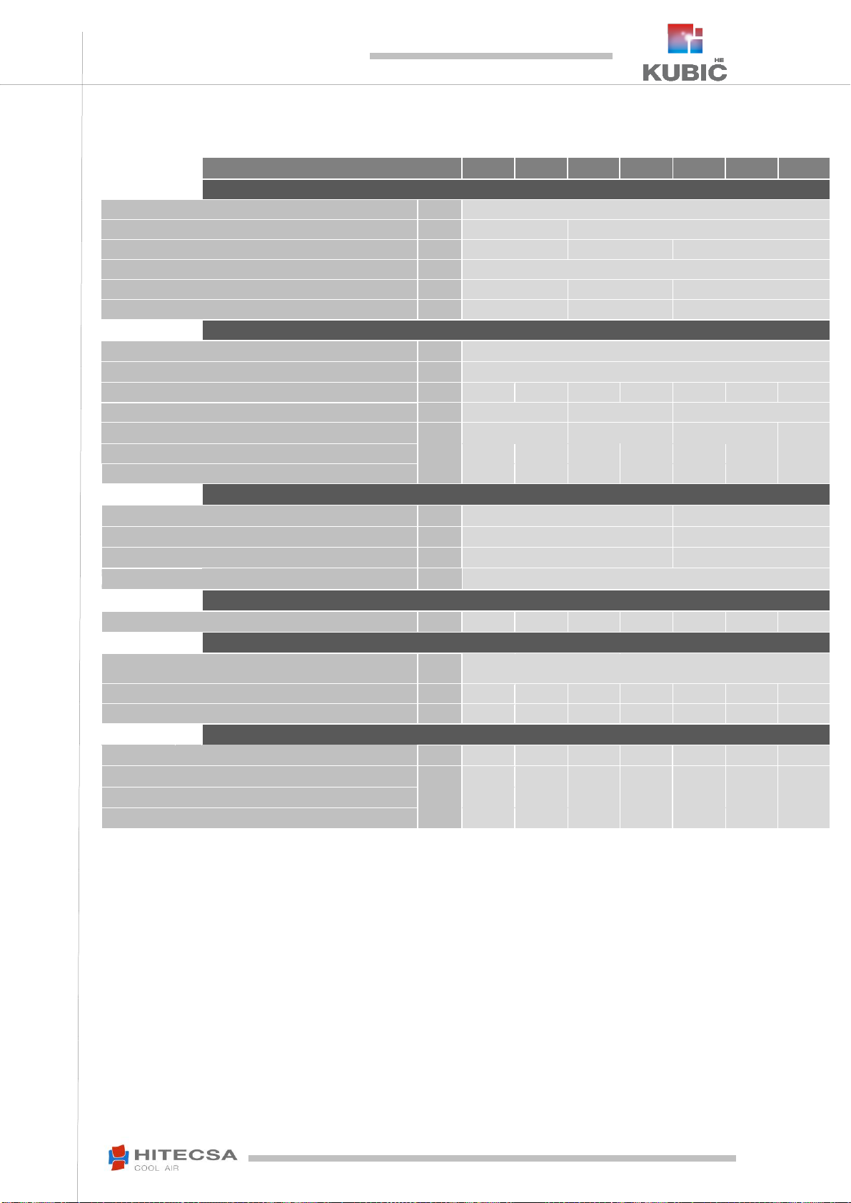
TECHNICAL SPECIFICATIONS
RMXRBA HE 102.3-219.4
KUBIC HE range
102.3
114.2
125.2
135.2
171.4
200.4
219.4
OUTDOOR FAN
Type
-
Axial Fan –Aluminium-copper Coil
Quantity
-
2
4
Nominal air flow
m³/h
45500
58500
76200
Available static pressure
Pa
0
Maximum absorbed power (Unit)
kW
2 x 2.06
4 x 1.25
4 x 2.06
Maximum absorbed Current (Unit)
A
2 x 3.8
4 x 3.0
4 x 3.8
INDOOR FAN
Type
-
Radial EC
Quantity
-
3
Nominal air flow
m³/h
19000
21000
23000
25000
28500
34000
37000
Standard available pressure
Pa
250
300
350
Nominal power
kW
3 x 2
3 x 3.6
3 x 3.4
3 x 5
Total absorbed power
kW
3.44
4.25
5.14
6.2
6.4
8,5
10,05
Max. available pressure
Pa
550
400
800
700
575
430
800
DIMENSIONS
Length
mm
3985
4330
Width
mm
2220
2240
Height
mm
1960
2300
Condensate water drain connection
Ø
3/4" Gas
WEIGHT
Net heat pump
kg
1805
1825
1951
1970
2850
3014
3032
ELECTRICAL DATA
Power supply
V /~/
Hz
400V / 3ph + N / 50Hz
Maximum absorbed current
A
98
116
130
137
146
173
192
Start current
A
274
282
341
341
317
352
376
SOUND POWER LEVEL (Lw)
Surround standard unit
dBA
88.7
89.4
91.2
91.9
89.2
92.8
94.2
Surround Unit working at 50% (4)
dBA
86.4
87.7
89.3
90.3
88.1
91.9
93.4
Surround Unit with compressor cover
dBA
87.9
88.1
90.4
91.2
88.7
91.8
93.3
Surround Unit at 50% (4) and compressor cover
dBA
85.3
86.8
88.6
89.7
87.9
91.3
92.9
(4) Unit working with the fan at speed 2 and with 50% capacity.
17
IOM_RMXRBA HE_40.3a200.4_207816_200308_EN
ROOF TOP UNITS –AXIAL FANS
RMXRBA HE
TECHNICAL SPECIFICATIONS
RMXRBA HE 102.3-219.4 RCF / VRC
KUBIC HE RCF/VRC range
102.3
114.2
125.2
135.2
171.4
200.4
219.4
NOMINAL CAPACITIES
COOLING MODE (5)
Cooling capacity RCF
kW
135,0
151,1
166,6
179,3
227,4
266,0
290,6
Total absorbed Power RCF
kW
37,3
45,0
50,6
56,9
61,4
78,8
88,7
Cooling capacity VRC
kW
107,7
120,5
132,9
143,0
181,4
212,2
231,8
Total absorbed Power VRC
kW
34,7
42,2
48,8
55,5
59,8
76,9
90,7
HEATING MODE (6)
Heating capacity RCF
kW
121,3
143,3
159,7
172,1
204,4
247,6
272,8
Total absorbed Power RCF
kW
38,2
46,1
53,6
59,3
64,4
81,9
91,4
Heating capacity VRC
kW
105,6
124,9
139,7
150,9
178,8
217,0
240,9
Total absorbed Power VRC
kW
33,6
40,9
48,6
54,6
59,2
75,5
88,5
SUPPLY FAN
Type
-
Radial EC
Quantity
-
3
Nominal air flow
m³/h
19000
21000
23000
25000
28500
34000
37000
Standard available pressure
Pa
250
300
350
Power input
kW
3 x 2
3 x 3,6
3 x 3,4
3 x 5
Total absorbed power
kW
3,44
4,25
5,14
6,2
6,4
8,5
10,05
Max. available pressure
Pa
550
400
800
700
575
430
800
RETURN FAN
Type
-
Radial EC
Quantity
-
3
4
Nominal air flow
Pa
19000
21000
23000
25000
28500
34000
37000
Standard available pressure
Pa
100
100
100
100
100
100
100
Max. operation current
A
3 x 3,16
3 x
5,56
3 x 8,04
4 x 5,56
DIMENSIONS
Length
mm
5930
6360
Width
mm
2220
2240
Height
mm
1960
2300
WEIGHT
RCF models Without options
kg
2610
2630
2756
2800
3865
4029
4047
VRC models Without options
kg
2465
2485
2611
2630
3640
3804
3822
ELECTRICAL DATA RCF
Power supply
V /~/ Hz
400V / 3ph + N / 50Hz
Maximum absorbed current
A
132
149
163
181
202
233
263
Start current
A
307
315
374
386
372
412
447
ELECTRICAL DATA VRC
Power supply
V /~/ Hz
400V / 3ph + N / 50Hz
Maximum absorbed current
A
108
125
139
153
171
197
214
Start current
A
283
291
350
358
341
376
398

18
IOM_RMXRBA HE_40.3a200.4_207816_200308_EN
ROOF TOP UNITS –AXIAL FANS
RMXRBA HE
OPERATION LIMITS
COOLING MODE
HEATING MODE
Temperature of return air mixture
Temperature of return air mixture
Outdoor Temperature
Temperature of return air mixture
Temperature of return air mixture

19
IOM_RMXRBA HE_40.3a200.4_207816_200308_EN
ROOF TOP UNITS –AXIAL FANS
RMXRBA HE
TRANSPORT & RECEPTION
INSPECTION AT RECEPTION
It is advisable to examine the equipment carefully upon reception.
Check that the equipment has not been damaged during transport and that it is complete with all the parts specified in
the order and/or the options stated in the order. If this is not the case please contact the transport company
immediately (within 48h).
Verify the correct voltage of the nameplate and make sure it is in accordance with local power supply.
In case of any flaw or anomaly detected, please contact HITECSA.
RIGGING
Before moving the unit, make sure that all panels are fixed properly.
Raise and put the equipment down carefully.
Do not tilt the unit more than 15 degrees during transportation (Fig. 1).
Always transport the unit in its original packaging to the place of installation.
All units come with a particular rigging diagram of that model similar to the one shown below. Be sure to hoist the
machine through the points indicated in the diagram.
Make sure that the unit is balanced, stable and without any deformations during the lifting operations.
STORAGE
If the equipment is going to be stored before the installation, please follow the following instructions in order to avoid
damages, corrosion or deterioration:
Move the equipment carefully.
Do not place the unit in places exposed to ambient temperatures above 50ºC and preferably keep the unit away from
direct sunlight.
Avoid placing the unit with plastic wrapping protection under the sun as the pressure of the circuits could reach values
that could lead to the activation of the safety valves.
Moreover, with decreasing temperatures water condensation may occur inside the machine and the plastic wrap.
Avoid placing other objects on top of the unit (unless this is done within the limits of the overlap planes indicated on the
packaging, etc. Follow these indications).
Avoid prolonged storage before installation, water penetration, dust and objects in general due to invasion or biological,
meteorological and/or human impacts.
Minimum storage temperature: -10ºC (No water must be stocked inside the equipment).
Maximum relative humidity: 90%.
Fig. 1

20
IOM_RMXRBA HE_40.3a200.4_207816_200308_EN
ROOF TOP UNITS –AXIAL FANS
RMXRBA HE
DIMENSIONS AND WEIGHT
WEIGHT OF STANDARD MODELS
MOD.
WEIGHT
REACTIONS (kg)
kg.
R1
R2
R3
R4
R5
R6
R7
R8
40.3
1080
168
240
137
166
234
136
-
-
45.3
1087
166
238
138
167
241
139
-
-
57.3
1155
176
253
147
177
256
147
-
-
71.3
1169
177
255
149
179
260
149
-
-
77.3
1217
185
267
155
186
269
155
-
-
102.3
1577
218
404
183
213
379
180
-
-
114.2
1594
220
409
185
216
383
182
-
-
125.2
1704
238
440
196
232
405
193
-
-
135.2
1721
241
443
197
235
410
194
-
-
171.4
2454
351
633
271
343
588
267
-
-
200.4
2624
380
674
288
371
627
284
-
-
219.4
2844
414
729
312
404
679
307
-
-
WEIGHT OF UNITS WITH RCF MODULE
MOD.
WEIGHT
REACTIONS (kg)
RCF
kg.
R1
R2
R3
R4
R5
R6
R7
R8
40.3
1460
145
261
201
126
145
257
199
126
45.3
1467
144
257
201
127
145
261
204
127
57.3
1557
153
272
214
135
154
277
216
135
71.3
1571
155
275
215
136
156
281
218
136
77.3
1677
163
290
234
147
163
295
237
148
102.3
2610
227
474
425
198
225
454
410
197
114.2
2630
229
480
427
199
227
459
412
198
125.2
2756
245
519
436
205
242
489
418
203
135.2
2800
248
524
444
209
245
496
427
207
171.4
3865
374
656
649
281
369
632
625
279
200.4
4029
396
700
658
289
391
673
635
287
219.4
4047
399
707
657
289
394
679
634
287
WEIGHT OF UNITS WITH VRC MODULE
MOD.
WEIGHT
REACTIONS (kg)
VRC
kg.
R1
R2
R3
R4
R5
R6
R7
R8
40.3
1380
143
253
182
115
142
249
180
115
45.3
1387
142
249
182
116
143
254
184
116
57.3
1455
150
262
190
121
151
267
192
121
71.3
1469
152
264
191
122
153
271
194
122
77.3
1517
158
275
197
125
159
279
198
126
102.3
2465
223
473
376
180
220
451
364
178
114.2
2485
225
479
377
181
223
455
366
179
125.2
2611
241
518
387
187
237
485
372
185
135.2
2630
243
523
387
187
240
491
373
186
171.4
3640
370
664
561
252
365
635
543
251
200.4
3804
392
708
571
259
386
677
554
258
219.4
3822
395
715
570
260
389
683
553
258
This manual suits for next models
36
Table of contents
Other Hitecsa Air Conditioner manuals

Hitecsa
Hitecsa ECV-SP 1001 User manual

Hitecsa
Hitecsa ACHIA 601 Installation and operating instructions

Hitecsa
Hitecsa Verne WPHA HE Series User manual

Hitecsa
Hitecsa WCHZ Series Owner's manual

Hitecsa
Hitecsa FPW 20 Owner's manual

Hitecsa
Hitecsa CCHBA/CCHA 201 Instruction manual

Hitecsa
Hitecsa EKWXA 1001.1 Instruction manual

Hitecsa
Hitecsa ACVA STD 401 Manual

Hitecsa
Hitecsa WCVZ Series Owner's manual

Hitecsa
Hitecsa DXCZ 171 Manual


