Hitecsa EQU-PF Series Operating instructions

MANUAL DE INSTALACIÓN, USO Y MANTENIMIENTO
IOM_EQU-PF EQUH PF_233a2160_207959_190702_ES-EN
EQU-PF EQUH PF
Enfriadoras de agua y bombas de calor reversibles monobloque de
alto
rendimientoconcondensaciónporaireyventiladorescentrífugos
tipoPlug-Fan
conmotoresEC.
Air-cooled chillers and heat pumps with radial fans.
Modelos: 233│238│245│250│260│265│270│280│290│2100│2115│2130│2145│2160
Models: 233│238│245│250│260│265│270│280│290│2100│2115│2130│2145│2160
SOLO FRIO
MANUAL DE INSTALACIÓN, USO Y MANTENIMIENTO
INSTALLATION, USER AND MAINTENANCE MANUAL

CONTENTS
4
English Page 4
Español página 28
CONTENTS SYMBOLS USED
I SECTION I: USER 5
I.1 Versions available.......................................................................................................5
I.2 Machine identification.................................................................................................5
I.3 Intended conditions of use.........................................................................................5
I.4 Operating limits...........................................................................................................6
I.5 Warnings regarding potentiallytoxic substances....................................................7
I.6 Residual risks and hazards that cannotbe eliminated ............................................8
I.7 PED Categories of Pressure Components................................................................8
I.8 Description of commands and controls....................................................................8
I.8.1 Main disconnection switch......................................................................................8
I.8.2 High and low pressure switches..............................................................................8
I.8.3 High and low pressure gauges (GM accessory) High pressure gauge: indicates the
high pressure value.................................................................................................8
II SECTION II: Installation and maintenance 9
II.1 Construction features.................................................................................................9
II.1.1 Available set-ups ....................................................................................................9
II.1.2 Electrical panel .......................................................................................................9
II.2 Accessories...............................................................................................................10
II.2.1 Factory fitted accessories.....................................................................................10
II.2.2 Accessories supplied separately...........................................................................10
II.3 Transport - Handling - Storage.................................................................................11
II.4 Installation.................................................................................................................11
II.4.1 Installation site requirements ................................................................................11
II.4.2 Indoor installation..................................................................................................11
II.4.3 Clearances and positioning...................................................................................11
II.4.4 Reduction of the unit's sound level........................................................................12
II.5 Electrical connections..............................................................................................13
II.6 Hydraulic connections..............................................................................................14
II.6.1 Connection to the system.....................................................................................14
II.6.2 Water data............................................................................................................15
II.6.3 Protection against corrosion .................................................................................15
II.6.4 Protecting the unit fromfreezing...........................................................................15
II.6.5 Heat recovery system...........................................................................................16
II.6.6 Installation suggestions.........................................................................................17
II.7 Start-up Procedure....................................................................................................18
II.7.2 General conditions of the unit...............................................................................19
II.8 Instructions for fine tuningand adjustments..........................................................22
II.8.1 Calibration of safety and control devices ..............................................................22
II.8.2 Operation of components......................................................................................22
II.9 Maintenance ..............................................................................................................23
II.9.1 Routine maintenance............................................................................................23
II.9.2 Special Maintenance ............................................................................................24
II.9.3 Repairing and replacing components....................................................................25
II.10 Dismantling the unit..................................................................................................25
II.11 Schematic troubleshooting......................................................................................26
ATTACHMENTS
A1 Technical data…................................................................................................52
A2 Dimensions and clearance… .............................................................................60
REFERENCE STANDARDS
UNI EN ISO 12100
Safety of machinery - General principles of design - Risk assessment
and risk reduction.
UNI EN ISO 13857
Safety of machinery - Safety distances to prevent hazard zones
being reached by upper and lower limbs.
UNI EN 563
Safety of machinery. Temperature of contact surfaces. Ergonomic
data to establish limit values for temperatures of hot surfaces.
UNI EN 1050
Safety of machinery. Principles of risk assessment.
UNI 10893
Product technical documentation. User instructions
EN 13133
Brazing. Brazer approval
EN 12797
Brazing. Destructive tests of brazed joints.
EN 378-1
Refrigeration systems and heat pumps –safety and environmental
requirements. Basic requirements, definitions, classification and
selection criteria
EN 378-2
Refrigeration systems and heat pumps –safety and environmental
requirements. Design, construction, testing, installing, marking and
documentation
IEC EN 60204-1
Safety of machinery. Electrical equipment of machines. Part 1:
General requirements
UNI EN ISO 9614
Determination of sound power levels of noise sources using sound
intensity.
EN 50081-1:1992
Electromagnetic compatibility - Generic emission standard Part 1:
Residential, commercial and light industry
EN 61000
Electromagnetic compatibility (EMC)
SYMBOL
MEANING
DANGER!
The DANGER sign warns the operator and
maintenance personnel about risks that may cause
death, physical injury, or immediate or latent
illnesses of any kind.
DANGER: LIVE COMPONENTS!
The DANGER: LIVE COMPONENTS sign warns the
operator and maintenance personnel about risks
due to the presence of live voltage.
DANGER: SHARP EDGES!
The DANGER: SHARP EDGES sign warns the
operator and maintenance personnel about the
presence of potentially dangerous sharp edges.
DANGER: HOT SURFACES!
The DANGER: HOT SURFACES sign warns the
operator and maintenance personnel about the
presence of potentially dangerous hot surfaces.
DANGER: MOVING COMPONENTS!
The DANGER: MOVING PARTS sign is used to
inform the operator and maintenance personnel of
hazards posed by the presence of moving parts.
IMPORTANT WARNING!
The IMPORTANT WARNING sign indicates actions
or hazards that could damage the unit or its
equipment.
ENVIRONMENTAL PROTECTION!
The environmental protection sign provides
instructions on how to use the machine in an
environmentally friendlymanner.

5
SECTION I: USER
I SECTION I: USER
I.1
VERSIONS AVAILABLE
2 33
2 38
2 45
2 50
2 60
2 65
2 70
2 80
2 90
2 100
2 115
2 130
2 145
2 160
(*) The power value used to identify the model is approximate. For the
exact value, identify the machine and consult the attachments
(A1Technical Data).
Available set-ups:
Standard:
Installation without pump and without storage tank.
Pump:
P1 –Installation with pump.
P2 –Installation with increased head pump.
DP1 –Installation with double pump, including one in standby with
automatic activation.
DP2 –Installation with increased head double pump, including one in
standby with automatic activation.
Tank & Pump:
ASP1 –Installation with pump and storage tank.
ASP2 –Installation with increased head pump and storage tank.
ASDP1 –Installation with double pump, including one in standby with
automatic activation, and storage tank.
ASDP2 –Installation with increased head double pump, including one
in standby with automatic activation, and storage tank.
In addition to that supplied with the Pump accessory, the unit also
includes:
1100 l flow inertial storage tank, expansion tank, safety valve, water
side pressure gauge, bleed valve, water drain valve and electrical
resistance connection.
I.2
MACHINE IDENTIFICATION
The identification data is found on the serial number plate, which is
located near the electrical panel. The serial number plate must not be
removed for any reason whatsoever; it must be destroyed when the unit
is scrapped.
I.3
INTENDED CONDITIONS OF USE
The EQU-PF units are packaged air-cooled water chillers with high
temperature/efficiency radial fans.
The EQUH-PF units are packaged reversible heat pumps on the
cooling circuit with air evaporation/condensation and radialfans.
They are intended to be used in air conditioning or industrial process
systems where chilled water (EQU-PF) or chilled and hot water
(EQUH-PF) is required, not for humanconsumption.
The units are designed for indoor installation.
DANGER!
The machine has been designed and constructed to
solely function as an air-cooled water chiller or as
an air-cooled heat pump; any other use is strictly
PROHIBITED.
It is prohibited to install the machine in an
explosive environment.
DANGER!
The machine is designed to be installed outdoors.
Segregate the unit if installed in areas accessible to
persons under 14 years of age.
IMPORTANT!
The unit will only function correctly if the
instructions for use stipulated in this manual are
strictly followed together with the specified
clearances during installation and the operating
limits.
n° of compressors Cooling capacity (kW) (*)

6
SECTION I: USER
I.4
OPERATING LIMITS
EQU-PF –EQUH-PF 233÷238 Models
In Summer mode In Winter mode
EQU-PF –EQUH-PF 245÷265 Models
In Summer mode In Winter mode
EQU-PF –EQUH-PF 270÷2160 Models
In Summer mode In Summer mode with BT accessory
T (°C) = Air temperature (D.B.).
t (°C) = Temperature of the water produced.
oMinimum water pressure 0.5 Barg.
oMaximum water pressure 6 Barg.
oMaximum water pressure on recoveries and desuperheater 3 Barg.
In Summer mode:
Maximum water inlet temperature 20°C.
In Winter mode:
Minimum water inlet temperature 20°C.
Maximum water inlet temperature 47°C.
If the water inlet temperature to the condensers is lower than the permitted
values, it is recommended to use a three-way modulating valve toguarantee
EQU-PF - EQUH-PF 270÷2160 Models
In Winter mode
the minimum water temperature required.
Operation with partialised cooling capacity.
Temperature differentials permitted through the exchangers
oTemperature differential at the evaporator ∆T = 3 ÷ 8°C (with all compressors on) for machines with a “Standard” set-up. The maximum and
minimum temperature differential for “Pump” and “Tank&Pump” machines is related to the performance of the pumps which always must be checked by
means of the selection software.
Nota bene: For t(°C) < 5°C use anti-freeze solutions (see "Use of anti-freeze solutions").

7
SECTION I: USER
I.5
WARNINGS REGARDING POTENTIALLY TOXIC
SUBSTANCES
DANGER!
Read the following ecological information and
requirements about the refrigerants employed
carefully.
I.5.1.1
Identification of the Type of Refrigerant
Fluid Used
Difluoromethane (HFC 32) 50% byweight
CAS No°: 000075-10-5
Pentafluoroethane (HFC 125) 50% byweight
CAS No°: 000354-33-6
I.5.1.2
Identification of the Type of Oil Used
The lubricant used in the unit is polyester oil; please refer to the
indications on the compressor data plate.
DANGER!
For further information regarding the
characteristics of the refrigerant and oil used, refer
to the safety data sheets available from the
refrigerant and oil manufacturers.
I.5.1.3
Main Ecological Information Regarding the
Types of Refrigerant Fluids Used
Persistence, degradation and environmental impact
Fluid Chemical formula GWP (over 100
years)
R32 CH2F2 550
R125 C2HF5 3400
HFC R32 and R125 refrigerants are the single components which make
up R410A when mixed at 50%. They belong to the hydrofluorocarbons
group and are regulated by the Kyoto protocol (1997 and subsequent
revisions) being gases that contribute to the greenhouse effect. The
index that measures the behaviour of the refrigerant to the
anthropogenic greenhouse effect is the GWP (Global Warming
Potential). The standard GWP index for carbon dioxide (CO2) is 1.
The value of GWP assigned to each refrigerant represents the
equivalent amount in kg of CO2 released over a period of 100 years, in
order to have the same greenhouse effect of 1 kg refrigerant released
over the same period of time.
The R410A mixture does not contain elements that are harmful to the
ozone, such as chlorine, therefore its ODP (Ozone Depletion Potential)
is zero (ODP=0).
Refrigerant R410A
Components R32 /
R125
Composition 50/50
ODP 0
GWP (over 100 years) 2000
SAFEGUARD THE ENVIRONMENT!
The hydrofluorocarbons contained in the unit
cannot be released into the atmosphere as they are
fluid that contributes to the greenhouse effect.
R32 and R125 are derived from hydrocarbons that decompose
relatively quickly into the lower atmosphere (troposphere).
Decomposition products are highly dispersible and therefore have a
very low concentration. They do not affect the photochemical smog, i.e.
they are not classified among VOC volatile organic compounds,
according to the UNECE agreement.
Effects on effluent treatment
Product waste released into the atmosphere does not cause long-term
water contamination.
Personal protection/exposure control
Use protective clothing and gloves; protect eyes and face.
Professional exposure limits:
R410A
HFC 32 TWA 1000 ppm
HFC 125 TWA 1000 ppm
Handling
DANGER!
Users and maintenance personnel must be
adequately trained about the risks involved when
handling potentially toxic substances. Failure to
comply with the above-mentioned guidelines can
cause personal injury or damage the unit.
Avoid inhalation of high concentrations of vapour. The atmospheric
concentration must be minimised and maintained at this minimum level,
below the occupational exposure limits. The vapours are heavier than
air, and therefore high concentrations may form close to the floor where
overall ventilation is poor. In this case, ensure adequate ventilation.
Avoid contact with naked flames and hot surfaces, which could lead to
the formation of irritant and toxic decomposition by-products. Do not
allow the liquid to come into contact with eyes or skin.
Measures to be taken in case of an accidental leak
Ensure adequate personal protection (using means of respiratory
protection) during clean-up operations. If the conditions are sufficiently
safe, isolate the source of leak.
If the amount of the spill is limited, let the material evaporate, as long as
adequate ventilation can be ensured. If the spill is considerable,
ventilate the area adequately.
Contain the spilt material with sand, soil, or other suitable absorbent
material.
Prevent the liquid from entering drains, sewers, basements or work pits,
as they can create a stifling environment.
I.5.1.4
Main Toxicological Information on the Type
of Refrigerant Used
Inhalation
A high atmospheric concentration can cause anaesthetic effects with
possible loss of consciousness. Prolonged exposure may lead to an
irregular heartbeat and cause sudden death.
Higher concentrations can cause asphyxia due to the reduced oxygen
content in the atmosphere.
Contact with skin
Splashes of nebulised liquid can produce frostbite. Unlikely to be
hazardous if absorbed through the skin. Repeated or prolonged contact
may remove the skin's natural oils, with consequent dryness, cracking
and dermatitis.
Contact with eyes
Splashes of liquid can cause frostbite.
Ingestion
While highly improbable, may produce frostbite.
I.5.1.5
First Aid Measures
Inhalation
Move the person away from the source of exposure, keep him/her warm
and let him/her rest. Administer oxygen if necessary. Attempt artificial
respiration if breathing has stopped or shows signs of stopping.
In the case of cardiac arrest carry out heart massage and seek
immediate medical assistance.
Contact with skin
In case of contact with skin, wash immediately with lukewarm water.
Thaw tissue using water. Remove contaminated clothing. Clothing may
stick to the skin in case of frostbite. If irritation, swelling or blisters
appear, seek medical assistance.
Contact with eyes
Rinse immediately using an eyewash or clean water, keeping eyelids
open, for at least ten minutes.
Seek medical assistance.
Ingestion
Do not induce vomiting. If the injured person is conscious, rinse his/her
mouth with water and make him/her drink 200-300 ml of water.
Seek immediate medical assistance.
Further medical treatment
Treat symptoms and carry out support therapy as indicated. Do not
administer adrenaline or similar sympathomimetic drugs following
exposure, due to the risk of cardiac arrhythmia.

8
SECTION II: INSTALLATION ANDMAINTENANCE
I.6
RESIDUAL RISKS AND HAZARDS THAT
CANNOT BE ELIMINATED
IMPORTANT!
Pay the utmost attention to the signs and symbols
located on the appliance.
Indelible safety instructions have been affixed identifying the potentially
dangerous parts if risks are still posed by the unit, which cannot be
technically eliminated, despite all the precautions taken during the
design phase. The warning labels must not be removed for any reason
whatsoever. A new label must be duly requested from the Spare Parts
Service if it should no longer be legible after having used, for example,
aggressive detergents.
I.8
DESCRIPTION OF COMMANDS AND
CONTROLS
The commands consist of the user interface panel (ref. 1), the general
circuit breaker (ref. 2).
I.8.1
Main disconnection switch
DANGER!
The instructions provided in the unit's wiring
diagrams must be strictly complied with if any
accessories not supplied are connected.
Manually controlled b-type power isolating device (ref. EN 60204-1 §
5.3.2). This switch disconnects the appliance from the mains electrical
power supply.
Indicates the presence of live components.
Indicates the presence of moving parts
(belts, fans).
Indicates the presence of hot surfaces
(refrigeration circuit, compressor heads).
Indicates the presence of sharp edges on finned
coils.
I.7 PED CATEGORIES OF PRESSURE
COMPONENTS
List of PED critical components (Directive 2014/68/UE).
Compressor I (233÷260) II (265÷2160)
Safety valve IV
High pressure switch IV
Low pressure switch -
Liquid receiver II
Liquid separator II
Finned coil Art. 3 Para. 3
Evaporator I (233÷250) II (260÷2160)
Oil separator -
0
1
I.8.2
High and low pressure switches.
DANGER!
The pressure switch is a safety device which
complies with standards in force. If tampered with
and/or modified, it could determine personal
danger.
The unit is equipped with two pressure switches for each individual
circuit. This device monitors two distinct functions:
High pressure switch: it trips to prevent working pressure from rising
excessively in the refrigeration circuit.
Low pressure switch: it monitors so that the low pressure side does
not drop below a certain value.
I.8.3
High and low pressure gauges (GM
accessory)
High pressure gauge: indicates the high pressure value.
Low pressure gauge: indicates the low pressure value.
Component PED category
1
2
MODE
Prg
ON
OFF

9
SECTION II: INSTALLATION ANDMAINTENANCE
II SECTION II: INSTALLATION AND
MAINTENANCE
II.1
CONSTRUCTION FEATURES
oLoad-bearing structure and panels in galvanised and RAL 9018
painted sheet metal; galvanised steel sheet metal base.
oThe structure consists of two sections:
technical compartment in galvanised sheet metal insulated internally
with noise-absorbing material for housing the compressors, the
electrical panel and the main components of the coolingcircuit;
Aeraulic compartment for housing the heat exchange coils, the plate
exchangers, the centrifugal Plug-Fans and accessories of the pumping
unit (if present).
oHermetic, Scroll-type rotary compressors complete with internal
thermal protection and crankcase resistance activated automatically
when the unit stops (provided the unit remains powered).
oAdequately insulated water side braze-welded plate heatexchanger
in stainless steel. Air side heat exchanger consisting of a coil in copper
pipes and aluminium fins.
oBrushless centrifugal Plug-Fans with internal thermal protection set
in a single row with horizontal flow.
oHorizontal condensation/evaporation flow opposite the finned coil or
vertical flow that can be transformed on site.
oElectronic proportional device for pressure and continuous
adjustment of the fan rotation speed, up to a minimum outdoor air
temperature of -10°C/-15°C when operating as a chiller, and up to a
maximum outdoor air temperature of 40°C when operating as a heat
pump.
oVictaulic-type hydraulic connections.
oThe differential pressure switch that protects the unit from any water
flow interruptions.
oSingle cooling circuit made of a mild copper tube (EN 12735-1-2)
complete with: cartridge drier filter, load connections, manually reset
high pressure safety switch, automatically reset low pressure switch,
safety valve/s, tap on the liquid line (only on 270-2160), thermostatic
expansion valve (1 for EQU-PF and 2 for EQUH-PF), cycle inversion
valve (for EQUH-PF), liquid receiver (for EQUH-PF) and non-return
valves (2 only on EQUH- PF), liquid indicator, gas separator in
compressor intake and solenoid valve on the liquid line (EQUH-PF
270-2160) and intake line insulation.
oUnit with IP24 protection rating.
oThe unit is complete with R410A refrigerant fluid.
oDucted drain for the condensation(EQUH-PF).
II.1.1
Available set-ups
Standard:
Installation without pump and without storage tank.
Pump:
P1 –Installation with pump.
P2 –Installation with increased head pump.
DP1 –Installation with double pump, one of which in standby with
automatic activation.
DP2 –Installation with increased head double pump, one of which in
standby with automatic activation.
The pumping unit is also complete with:
Expansion tank, safety valve and water side pressure gauge.
In the case of a single pump, the unit is also complete with a delivery
shut-off valve.
In the case of a double pump, the unit is complete with a non-return
valve and an intake valve for each pump.
Tank & Pump:
ASP1 –Installation with pump and storage tank.
ASP2 –Installation with increased head pump and storage tank.
ASDP1 –Installation with double pump, one of which in standby with
automatic activation and storage tank.
ASDP2 –Installation with increased head double pump, one of which in
standby with automatic activation and storage tank.
In addition to that supplied with the Pump accessory, the unit also
includes:
Flow inertial storage tank (150 l for models 233-265; 250 l for models
270÷2100, 450 l for models 2115÷2160), relief valve, water drain valve
and electrical resistance connection.
II.1.2
Electrical panel
oElectrical panel accessed by opening the front panel, compliant with
IEC Standards in force, can be opened and closed with a suitabletool.
oComplete with:
electrical wiring for 400V-3ph+N-50Hz power voltage;
230V-1ph+N-50Hz auxiliary circuit power supply from the main
power supply;
24V-1ph-50Hz control power supply from the main power supply;
main isolating switch on the power supply, complete with a door
locking safety device;
automatic circuit breaker switch protecting the compressors and
fans;
protection fuse for the auxiliary circuit;
compressor power contactor;
machine remote controls: ON/OFF and summer/winterselector;
remote machine controls: compressors work light and general block
light.
oProgrammable electronic board with microprocessor, controlled by
the machine keyboard.
oThe board performs the following functions:
regulation and control of the machine outlet water temperature
settings; of the cycle inversion (EQUH-PF); of the safety timers; of the
circulation pump; of the system compressor and pump hour-run meter;
of the pressurised defrost cycles; electronic anti-freeze protection that is
automatically activated when the machine is off; and of the functions
that control the operations of the individual parts making up the
machine;
complete protection of the machine, possible shutdown and display
of all the triggered alarms;
compressor protection phase sequence monitor;
unit protection against low or high supply voltage on the phases;
display of the programmed settings; of the in/out water temperatures
via the display; of the condensation and condensation/evaporation
pressures (EQUH-PF); of the voltage values in the three phases of the
electrical circuit that powers the unit; of the alarms via the display; and
of the chiller or heat pump operation via the display (EQUH-PF);
user interface menu;
automatic pump operating time balance (DP1-DP2, ASDP1- ASDP2
set-ups);
pump standby automatic activation in case of an alarm (DP1-DP2,
ASDP1-ASDP2 set-ups);
displayed inlet water temperature at the recovery
unit/desuperheater;
alarm code and description;
alarm history management (manufacturer password-protected
menu).

10
SECTION II: INSTALLATION ANDMAINTENANCE
oThe following is memorised for each alarm:
date and time of intervention (if the KSC accessory ispresent);
in/out water temperature values as soon as the alarm istriggered;
the condensation pressure values at the time of the alarm
alarm delay from when the connected device is switched on;
compressor status at the time of the alarm;
oAdvanced functions:
Hi-Pressure Prevent function with forced cooling capacity
partialisation for a high outdoor temperature (in summermode),
set-up for serial connection (KRS485, KFTT10, KRS232, KUSB
accessory);
possibility to have a digital input for remote management of the
double Set point (see the Pre-sales Department);
possibility to have an analogue input for the shifting Set-point via a
4-20mA remote signal (contact Pre-sales Department);
set-up for management of time bands and operating parameters with
the possibility of daily/weekly operating programs (KSC accessory);
check-up and verification of the scheduled maintenancestatus;
computer-assisted machine testing;
self-diagnosis with continuous monitoring of the machine operating
status.
II.2
ACCESSORIES
II.2.1
Factory fitted accessories
P1 –Installation with pump.
P2 –Installation with increased head pump.
DP1 –Installation with double pump, one of which in standby with
automatic activation.
DP2 –Installation with increased head double pump, one of which in
standby with automatic activation.
ASP1 –Installation with pump and storage tank.
ASP2 –Installation with increased head pump and storage tank.
ASDP1 –Installation with double pump, one of which in standby with
automatic activation and storage tank.
ASDP2 –Installation with increased head double pump, one of which in
standby with automatic activation and storage tank.
INS–Soundproofed compressors with noise-absorbing ear muff
(solution that reduced the noise of the compressors).
RA –Evaporator anti-freeze resistance, prevents the risk of ice
formation inside the exchanger when the machine is switched off
(provided the unit remains powered).
RDR –Desuperheater/recovery unit anti-freeze resistance (DS or
RC100), prevents the risk of ice formation inside the recovery unit
exchanger when the machine is switched off (provided the unit remains
powered).
RAS –300W storage tank anti-freeze resistance (available for ASP1-
ASDP1- ASP2-ASDP2 set-ups); prevents the risk of ice formation inside
the exchanger tank when the machine is switched off (provided the unit
remains powered).
RAE 1 –27W electric pump anti-freeze resistance (available for P1-
DP1-ASP1-ASDP1 set-ups); prevents the risk of the water inside the
pump becoming ice when the machine is switched off (provided the unit
remains powered).
RAE 2 –27W double electric pump anti-freeze resistance (available for
P2-DP2-ASP2-ASDP2 set-ups); prevents the risk of the water inside the
pumps becoming ice when the machine is switched off (provided the
unit remains powered).
DS –Desuperheater; it is not active during heat pump operation.
RC100 –Heat recovery unit with 100% recovery; the accessory is
complete with a differential pressure switch on the recovery unit
exchanger. It does not work as a heat pump.
GM –Cooling circuit high and low pressure gauges.
SFS –Soft-Start device to reduce the peak current in the start-up phase
(weight 40 Kg).
FTT10 –FTT10 serial interface board for connection to supervision
systems (LonWorks® system compliant with Lonmark® 8090-10 protocol
with chiller profile).
SS –RS485 serial interface board to create dialogue networks between
boards (maximum: 200 units for a max. distance of 1000 m) and the
building automation or external supervision systems.
CR –Power factor correction capacitors (cosΦ > 0.91).
EEV –Electronic thermostatic valve.
RAP –Unit with copper/pre-painted aluminium coils.
BRR –Unit with copper/copper coils.
DSP –Double Set-point via digital consensus (incompatible with the CS
accessory).
BT –low temperature of water produced (only for models 270÷2160).
CS –4-20 mA analogue signal for shifting Set-point (incompatible with
the DSP accessory). The EEV accessory may have to be also installed,
depending on the required values.
RPB –Coil protection mesh with accident-prevention function.
IMB –Protective packaging.
II.2.2
Accessories supplied separately
KFA - Water filter (only for models 233÷265).
KRAS - Fitting for connection to the inlet duct.
KRMA - Antivibration fitting for connection to the outlet duct.
KSA –Rubber antivibration mountings.
KRIT –Additional electrical resistance heater for heat pump only for
233÷265.
KEAP –Outdoor air temperature probe for Set-point compensation
(incompatible with the CS accessory).
KTR –Remote control keyboard with backlit LCD display (same
functions as that on the machine).
KSC –Clock card to display the date/time and machine time band
management with daily and weekly start/stop time bands, with the
possibility of changing the Set-points.
KRS485 –RS485 serial interface board to create dialogue networks
between boards (maximum: 200 units for a max. distance of 1000 m)
and the building automation or external supervision systems.
KFTT10 –FTT10 serial interface board for connection to supervision
systems (LonWorks® system compliant with Lonmark® 8090-10 protocol
with chiller profile).
KISI –CAN bus serial interface (Controller Area Network).
KRS232 –RS485/RS232 serial converter for interconnection between
the RS485 serial network and supervision systems with serial
connection to the PC via the RS232 serial port (RS232 cable supplied).
KUSB –RS485/USB serial converter for interconnection between the
RS485 serial network and supervision systems with serial connection to
the PC via the USB port (USB cable supplied).
KMDM –GSM 900-1800 modem kit to be connected to the unit for
remote management of the parameters and any alarm signals. The kit
consists of a GSM modem with relative RS232 board. A SIM data card,
not supplied must be purchased.
KRS –Supervision software for the monitoring and remote
management of the units. The kit consists of a CD-Rom and hardware
key.

11
SECTION II: INSTALLATION ANDMAINTENANCE
II.3
TRANSPORT - HANDLING - STORAGE
DANGER!
The unit must be transported and handled by
skilled personnel trained to carry out this type of
work.
IMPORTANT!
Be careful to avoid damage by accidental collision.
II.3.1.1
Packaging, components
DANGER!
Do not open or tamper with the packaging before
installation. Do not leave the packaging within
reach of children.
ENVIRONMENTAL PROTECTION
Dispose of the packaging materials in compliance
with the national or local legislation in force in your
country.
Each unit is supplied complete with:
User instructions;
Wiring diagram;
List of authorised service centres;
Warranty documents;
Safety valve certificates;
Use and maintenance manuals for the pumps, fans and safety
valves.
II.3.1.2
Lifting and handling
ATTENTION!
The unit was not designed to be lifted with a forklift
truck.
DANGER!
The unit must be handled with care, in order to
prevent damaging the external structure and the
internal mechanical and electrical components.
Also make sure that there are no obstacles or
people blocking the route, to avoid the danger of
collision or crushing. Make sure that there is no
possibility of the lifting-gear overturning.
Pass the straps through the slots in the base of the unit, having first
checked their suitability (capacity and wear and tear). Tension the
straps, checking that they remain properly attached to the upper edge
of the passage; lift the unit a few centimetres and, only after checking
the stability of the load, move the unit carefully to the installation site.
Lower the unit carefully and fix it into place. Be careful not to interpose
body parts one handling in order to eliminate any possible risk of
crushing or any other injury if the load drops or shifts suddenly.
II.3.1.3
Storage conditions
The units cannot be stacked. The temperature limits for storage are: -20
÷ 50°C.
II.4
INSTALLATION
DANGER!
Installation must only be carried out by skilled
technicians, qualified to work on air conditioning
and refrigeration systems. An incorrect installation
could cause the unit to malfunction with a
significant deterioration in performance.
DANGER!
The unit must be installed according to national or
local regulations in force at the time of installation.
Some internal parts of the unit can cause cuts. Use
suitable individual protective equipment.
If the unit is not secured on the antivibration mounts, it must be firmly
anchored to the floor once it is placed on the ground.
It must not be installed on brackets or shelves.
II.4.1
Installation site requirements
The installation site must be chosen in accordance with the provisions
of Standard EN 378-1 and in line with those of Standard
EN 378-3. When selecting the installation site, risks posed by an
accidental leakage of refrigerant gas from the unit must also be taken
into consideration. Do not install the unit near flammable materials or
others that could cause a fire. Provide the specific fire-prevention safety
devices.
II.4.2
Indoor installation
The technical rooms intended for the installation of cooling units must
always be constructed in compliance with accident prevention
legislation in force in the country in question.
Technical rooms are not normally constructed exclusively for the
installation of cooling machines. In many cases, there can also be other
equipment present, such as burners that run on gas, solid fuel or liquid
fuel, with a consequent increase in risks to personal safety.
II.4.3
Clearances and positioning
IMPORTANT!
Before installing the unit, verify the noise limits
allowed in the place in which it will be used.
IMPORTANT!
The unit must be positioned in compliance withthe
minimum recommended clearance, bearing in mind
the access to the water and electricalconnections.
IMPORTANT
If the technical spaces are not complied with during
installation, then unit could malfunction with an
increase in absorbed power and a significant
reduction in cooling capacity.
The unit is designed for indoor installation. The unit must be installed in
compliance with the minimum recommended clearance, bearing in mind
the access to the water and electrical connections on the right side of
the machine. The unit should be correctly levelled and positioned on a
supporting surface capable of sustaining its full weight. It must not be
installed on brackets or shelves.
To allow the EQU-PF - EQUH-PF to run smoothly it is recommended
not to mix the drawn air with the expelled air, therefore it is
recommended for the fan supply air to be channelled out of the room
where the unit is installed.

12
SECTION II: INSTALLATION ANDMAINTENANCE
The section of the supply channel must always be constant and equal
of the walls of the room.
However it is installed, the coil inlet air temperature (ambient air) must
remain within the set limits.
II.4.4
Reduction of the unit's sound level
Correct installation involves taking precautions aimed at reducing the
noise deriving from the unit's standard operation.
IMPORTANT!
Incorrect positioning or installation of the unit can
amplify noise levels or vibrations generated during
operation.
When installing the unit, bear the following in mind:
non-soundproofed reflecting walls near the unit, such as terrace
walls or building perimeter walls, can increase the total sound pressure
level read near the appliance by 3 dB(A) for every surface (e.g. 2 corner
walls correspond to a 6 dB(A) increase);
install suitable antivibration mounts under the unit to prevent
vibrations from being transmitted to the building structure;
solid floor frames can be set up on top of buildings to support the
unit and distribute its weight to the bearing elements of thebuilding;
make all water connections using elastic joints; pipes must be firmly
supported by solid structures. If the pipes are routed through walls or
panels, insulate with elastic sleeves
If, after installation and start-up of the unit, structural vibrations are
noted in the building, which cause such strong resonance to generate
noise in certain parts of the building, contact a qualified acoustic
technician for a complete analysis of the problem.
The following accessories are available to reduce noise and
KSA - Antivibration supports.
KRAS –Inlet antivibration connection
KRAM –Outlet antivibration connection
When installing the unit, bear the following in mind:
non-soundproofed reflecting walls near the unit can increase the
total sound pressure level read near the appliance by 3 dB(A) for every
surface;
install suitable antivibration mounts under the unit to prevent
vibrations from being transmitted to the building structure; make all
water connections using elastic joints; pipes must be firmly supported
by solid structures. If the pipes are passed through walls or panels,
insulate with elastic sleeves. If, after installation and start-up of the unit,
structural vibrations are noted in the building, which cause such strong
resonance to generate noise in certain parts of the building, contact a
qualified acoustic technician for a complete analysis of theproblem.
vibration:
to that of the fan. The KRAM kit (outlet antivibrationconnection) is Model L1
L2
L3
L4
available to prevent vibrations from being transmitted andallows the 233 mm 1000
1500
1500
1000
unit to be separated from the channel. It is however recommended to 238
mm
1000
1500
1500
1000
introduce flexible connections on the air channel at thecrossing points 245
mm
1000
1500
1500
1000
The room in which the unit is to be installed must have anopening that 250
mm
1000
1500
1500
1000
allows the air to be drawn from the outside through a section that is
260
mm
1000
1500
1500
1000
equal to the surface of the finned coil.
265
mm
1000
1500
1500
1000
The intake can be channelled. The KRAS kit (inlet antivibration
270
mm
1000
1500
1500
1000
connection) is available to prevent vibrations from being transmitted.
280
mm
1000
1500
1500
1000
When the channelling is implemented, the total air pressure drops at
290
mm
1000
1500
1500
1000
nominal flow rate must be evaluated, which must be less than the
2100
mm
1000
1500
1500
1000
available head at the same capacity.
2115
mm
1000
1500
1500
1000
2130
mm
1000
1500
1500
1000
2145
mm
1000
1500
1500
1000
2160
mm
1000
1500
1500
1000

13
SECTION II: INSTALLATION ANDMAINTENANCE
II.5
ELECTRICAL CONNECTIONS
IMPORTANT!
Always install a general circuit breaker in a
protected area near the device with a delayed
characteristic curve, adequate capacity and
breaking power. There should be a minimum
distance of 3 mm between the contacts. The earth
connection is mandatory by law and protects the
user while the machine is in use
IMPORTANT!
Refer to the wiring diagrams attached to the unit, in
which the terminals to be set up by the installer are
highlighted.
DANGER!
The electrical connection of the unit must be
carried out by qualified personnel in compliance
with the regulations in force in the country where
the unit is installed. Shall not be held liable for
damage to persons or property caused by a non-
compliant electrical connection. In making the
electrical connections to the board, cables must be
routed so that they do not touch the hot parts of the
machine (compressor, flow pipe and liquid line).
Protect the wires from any foam.
All the connections carried out during installation must be secured
against accidental loosening. It is particularly important for the earth
wire to be longer than the others so that it is the last to stretch if
detached.
The electrical connection wires must pass through ducts having a
minimum protective rating of IP33 (in accordance with EN60529).
Pay particular attention for the presence of sharp edges, burrs,
rough surfaces in general or threads in order to make sure the wire
insulation is not damaged.
Cable ducts must be anchored securely to the floor or walls.
If people walk through the area where the cable is installed, it must
be set at least 2 metres above the work area.
H07RN-F-type cables or in any case a cable with “no vertical flame
propagation on a single cable” must be used, in accordance with test
IEC 20-35/1-1 (EN 50265-2-1), provided in standards IEC 20-19,
CENELEC HD22 with a minimum cross-section according to that
stipulated in the wiring diagrams attached to the unit.
It is mandatory for the unit to be earthed. It must be set-up during
installation using the specific clamp with the earthingmark.
The power supply cables must pass through external cableglands
underneath the electrical panel.
IMPORTANT!
Before connecting the main power supply cables
L1-L2-L3 to the terminals of the general circuit
breaker, make sure that they are in the right order.
245 mm² 10 10 1,5
2130 mm² 35 16 1,5
II.5.1.1
Remote management through connections
set up by the installer
The connections between board and switch or remote light must be
carried out with the screened cable consisting of 2 twisted 1.5 mm²
wires and the screen. The screening must be connected to the earth
screw on the panel (on one side only). The maximum permitted
distance is 30 m.
CS Shifting Set-point (4÷20 mA signal);
SDS Double Set-point selector (control with potential free
contact);
SCR Remote control selector (control with potential-free
contact);
SEI Remote summer/winter selector
(control with potential freecontact);
LBG General lockout light (230 Vac);
LFC1 Compressor 1 work light (230 Vac);
LFC2 Compressor 2 work light (230Vac);
Remote ON/OFF enabling (SCR).
IMPORTANT!
When the unit is switched OFF using the remote
control selector, the message OFF by digital input
appears on the control panel display on the
machine.
Remove the terminal bridge on the board in the electrical panel and
connect the wires coming from the remote control ON/OFF selector
(selector to be installed by the installer).
ATTENTION
Open contact: the unit is OFF.
Closed contact: the unit is ON.
Remote summer/winter enabling on EQUH-PF Connect the
wires coming from the remote summer/winter selector on to the
terminals in the electric panel.
Then modify the Rem. Summer/Winter parameter
ATTENTION
Open contact: heating cycle
Closed contact: cooling cycle
LBG –LCF1 –LCF2 remote control
To remotely control the two signals, connect the two lamps according to
the instructions provided in the wiring diagram supplied with the
machine.
II.5.1.2
Remote control with the control panel
installed on the machine or with a second
keyboard (KTR: remote keyboard)
The remote keyboard (KTR) allows all the unit's digital and analogue
process variables to be remote controlled and displayed. This
accessory precisely reproduces the functions of the keyboard and the
microprocessor electronic controller installed on the machine. It is
therefore possible to control all the unit functions directly in the room.
The control panel installed on the machine can be remote controlled
after having removed it from the unit, making sure not to damage it.
Close the hole on the door of the electrical panel so that humidity
does not infiltrate.
If you wish to remote control a second keyboard (KTR), remove the
telephone cable connector from its seat in the unit control panel and
insert the remote control connector.
ATTENTION!
Make sure the electrical supply has been
disconnected from the system before starting any
operation.
Follow these guidelines to connect the Area Terminal:
use a 6-wire telephone cable and RJ12-type connectors;
head the cable according to the figures below;
the length of the cable must not exceed 50 m (*);
keep the telephone cable separate from the inductive and power
loads inside the unit;
use the cable ducts intended for the signal cables inside the
electrical panel;
never insert the telephone and power cables in the same cable
ducts when connecting the Area Terminal and the chiller/heat
pump board.
Commands and
controls
PE
Line
Model

14
SECTION II: INSTALLATION ANDMAINTENANCE
N
N
O
C
0
S9
Proceed as follows to connect the Area Terminal to the Chiller/heat
pump board:
remove the panel that protects the electrical panel;
pass the telephone cable coming from the Area Terminal through
the cable glands on the electrical panel and thestructure;
engage the end of the telephone cable with the J13 female
connector on the unit electronic board;
re-mount the previously-removedpanels.
Rx/Tx-
Rx/Tx+
GND
(*) Note: an AWG 20/22 shielded cable (4 wires + shield) and two
branching boards (use the E968573484 KIT) must be used to connect
the KTAU and the electronic board of the chiller/heat pump when the
length exceeds 50 m and reaches a maximum of 200 m. As shown in
the diagram below.
200 m
II.6
HYDRAULIC CONNECTIONS
II.6.1
Connection to the system
IMPORTANT!
The hydraulic system and the connection of the unit
to the system must be carried out in compliance
with local and national regulations in force.
IMPORTANT!
Shut-off valves that isolate the unit from the rest of
the system must be installed. It is mandatory to
install square mesh filters (longest side = 0.8 mm),
which are suitably sized and of adequate pressure
drops for the system. Clean the filter from time to
time.
The standard unit is equipped with Victaulic fittings with welding carbon
steel fittings (refer to the attached tables for the position and size of the
fittings).
The pipes must be mechanically insulated and supported to prevent the
unit from being subjected to anomalous stress.
Shut-off valves that isolate the unit from the rest of the system and
elastic connection joints must be installed, as well as system/machine
drain taps.
The rate of the water that flows through the heat exchanger must not
drop below the value corresponding to a temperature differential of 8°C
(with both compressors on).
The unit must be correctly levelled and positioned on a supporting
surface capable of sustaining its full weight.
During long periods of inactivity, it is advisable to drain the water from
the system.
Ethylene glycol must be added to the hydraulic circuit in order to avoid
draining the water.
oTo allow the units to run smoothly it is recommended not to mix the
drawn air with the expelled air, therefore the supply air must be
channelled and expelled out of the room where the unit is installed.
oThe section of the supply channel must always be equal to or
greater than that of the fan. The KRAM kit (outlet antivibration
connection) is available to prevent vibrations from being transmitted and
allows the unit to be separated from the channel. The room in which the
unit is to be installed must have an opening that allows the air to be
drawn from the outside through a section that is at least equal to the
surface of the finned coil.
oThe intake can be channelled. The KRAS kit (inlet antivibration
connection) is available to prevent vibrations from beingtransmitted.
oRefer to the total air flow rates according to the desired speeds and
pressure drops in the expulsion system to size thechannelling.
C = AWG 20/22 shielded cable (4 wires + shield) (not supplied)
S = shield of the shielded cable
D = branching board (E968573484)
T = telephone cable (E968573484)
AP1 = Electronic chiller/heat pump board
2 1
0,8 m
0,8 m
1
2
3
4
5
6
Bianco White Blanc Weiss Blanco
1
2
3
4
5
6
Nero Black Noir Schwarz Negro
Rosso Red Rouge Rot Rojo
Giallo Yellow Jaune Gelb Amarillo
Blu Blue Bleu Blau Azul marino

15
SECTION II: INSTALLATION ANDMAINTENANCE
II.6.1.1
Installing and controlling the utility pump
The circulation pump installed on the chilled water circuit must have
characteristics that are not affected by any pressure drops of the entire
system and the machine heat exchanger, at the nominal flow.
The differential pressure switch that protects the unit also protects it
from any water flow interruptions. It is automatically reset and the unit
restarts automatically only when the water flow exceeds the calibration
setting differential.
In any case, after it intervenes, the control panel displays the
corresponding alarm to signal possible problems in the hydraulic
system.
The operation of the user pump must be subordinated to the
operation of the unit; the microprocessor controller checks the operation
of the pump according to the following logic:
at start-up, the first device to start in the system is the pump, which
has priority over the rest of the system.
during start-up, the minimum water flow differential pressure switch
installed on the unit is ignored for a preset time, in order to prevent
variations caused by air bubbles or turbulence in the watercircuit.
once the set time elapses, final consent for the machine to start-upis
accepted and 60 seconds after the pump is started up, the fans are
activated (the anti-freeze alarm is bypassed during this phase). After a
further 60 seconds the compressors are activated according to the
safety times. The pump remains on for as long as the unit keeps
running and only shuts down at the switch-off command.
when the machine is switched off, the pump will continue to run for a
pre-set time before finally stopping, in order to disperse the residual
cold in the evaporator.
II.6.1.2
Minimum water circuit content
For the unit to run smoothly, a minimum amount of water must be in the
water system. The minimum water content is established on the basis
of the unit's nominal cooling capacity (A Technical Data), multiplied by
the coefficient expressed in l/kW.
If the minimum content in the system is below the minimum value
indicated or calculated, it is advisable to select the TANK&PUMP
accessory complete with inertial storage tank, and possibly install an
additional tank. However, in process applications it is always advisable
to use a storage tank or a greater system water content to guarantee
higher system thermal inertia.
The minimum water content of the circuit is 2 l/kW
Volume less than 2 l/kW would cause large thermal variation and
could reduce the life of the compressor.
IMPORTANT!
Volume less than 2 l/kW would cause large thermal
variation and could reduce the life of the
compressor.
II.6.2
Water data
II.6.3
Protection against corrosion
Do not use water that is corrosive or contains deposits or debris.
Specific heat exchangers must be used if the water used contains
chloride or is demineralised (stipulated in the documentation, where
available). The corrosive limits for braze-welded stainless steel
exchangers are found below:
pH 7.5 ÷ 9.0
SO4-- < 70 ppm
HCO3-/SO4-- > 1.0 ppm
Total hardness 4.0 ÷ 8.5 dH
CI- < 50 ppm
PO43- < 2.0 ppm
NH3 < 0.5 ppm
Fe+++ < 0.2 ppm
Mn++ < 0.05 ppm
CO2 < 5 ppm
H2S < 50 ppb
Temperature < 65 °C
Oxygen content < 0.1 ppm
Alkalinity (HCO3) 70 ÷ 300 ppm
Electrical Conductivity 10 ÷ 500 µS/cm
Nitrate (NO3) < 100 ppm
If you are uncertain about the quality of the water in the above table or
you have doubts regarding the presence of different materials that could
cause gradual corrosion over time in the exchanger, it is always good
practice to insert an intermediate exchanger that can be inspected and
is made of suitable resistant material.
II.6.4
Protecting the unit from freezing
II.6.4.1
Indications for unit when idle
IMPORTANT!
If the unit is not used during the winter period, the
water contained in the system may freeze.
The entire circuit must be drained in good time. A drainage point below
the water exchanger must be used to make sure all the water empties
out. Moreover, use the valves placed in the lower part of the water
exchanger so that is empties completely.
If the draining operation is felt to be too much trouble, ethylene glycol
can be mixed with the water in suitable proportions in order to
guarantee protection from freezing.
Units are available with an antifreeze resistance (RA accessory) to keep
the evaporator intact, should the temperature drop excessively.
IMPORTANT!
The unit must not be disconnected from the
electrical power supply during the entire seasonal
break

16
SECTION II: INSTALLATION ANDMAINTENANCE
II.6.4.2
Indications for unit when operating
In this case, it is the microprocessor control board which protects the
evaporator from freezing. When the set temperature has been reached,
the antifreeze alarm is triggered stopping the unit, while the pump
keeps running normally.
The use of ethylene glycol is recommended if you do not wish to drain
the water from the hydraulic system during the winter break or if the unit
must supply chilled water at temperatures lower than 5°C (the latter
case is not considered here and depends on the size of the unit
system).
Table “H” indicates the multipliers that allow the unit performance
changes to be determined in proportion to the required percentage of
ethylene glycol.
The multipliers refer to the following conditions: condenser inlet air
temperature 35°C; chilled water temperature 7°C; temperature
differential at evaporator 5°C.
For different operating conditions, the same coefficients can be used as
their variations are negligible.
IMPORTANT!
Mixing the water with glycol modifies the
performance of the unit.
Use of anti-freeze solutions with BT accessory
The table indicates the ethylene/propylene glycol percentages to be
used in units with the BT accessory based on the produced chilled
water temperature. Contact pre-sales service for information regarding
performance of the units.
From -3°C to -8°C 30%
From 0°C to -2°C 20%
From 4°C to 1°C 10%
Table “H”
Minimum outdoor air temperature °C
2
0
-3
-6
-10
-15
-20
% glycol in weight
10
15
20
25
30
35
40
Freezing temperature in °C
-5
-7
-10
-13
-16
-20
-25
fc G
1,025
1,039
1,054
1,072
1,093
1,116
1,14
fc ∆pw
1,085
1,128
1,191
1,255
1,319
1,383
1,468
fc QF
0,975
0,967
0,963
0,956
0,948
0,944
0,937
fc P
0,993
0,991
0,99
0,988
0,986
0,983
0,981
fc QF = Cooling capacity correction factor.
fc P = Correction factor for the total absorbed electrical current.
fc ∆pw = Correction factor of the pressure drops in the evaporator.
fc G = Correction factor of the glycol water flow to the evaporator.
II.6.5
Heat recovery system
II.6.5.1
Operation
To recover the heat from the compressor and consequently produce hot
water, the differential pressure switch (PD) must give its consent to the
electronic board; to achieve this result, the circulating pump (P) must be
active and the water must circulate normally in the recovery exchanger.
The electronic board also controls the recovery unit and/or
desuperheater (ST8) outlet temperature so as to guarantee the
maximum outlet temperature.
II.6.5.2
Installation precautions
DANGER!
The recovery unit / desuperheater is set directly in
series with the compressors; therefore, the internal
temperature of the recovery exchanger can reach
120°C at a pressure of 2 bar, in particular faulty
conditions. This could lead to the formation of
steam from overheated water.
Minimum % glycol in
weight
Evaporator glycol
water outlet temperature

17
SECTION II: INSTALLATION ANDMAINTENANCE
II.6.6
Installation suggestions
Particular attention must be paid to the system operating pressure,
which must not exceed the values indicated on the plate of the
individual components and must be within limits so as to prevent the
water in the recovery unit from boiling.
Continuous circulation of water through the recovery unit or the
desuperheater must be guaranteed by means of mixing units.
Closed circuit system (e.g. for heating)
RC100 –Recovery unit
DS –Desuperheater
M –Pressure gauge
VS –Safety valve
VE –Expansion tank
VSTB –DHW boiler temperature relief valve
VSTR –Recovery unit temperature relief valve
VSM –Manual air bleed valve
VSAM –Automatic/manual air bleed valve
TSB –DHW boiler safety thermostat
VR –Non-return valve
VM –Three-way mixer valve
PU –Circulation pump
PD –RC100/DS consensus differential pressure switch
FC –Fan coil
UT –Upon use
RI –From the water mains
ST –Temperature probe
SI –Intermediate exchanger
ST8 –RC100/DS outlet temperature probe
VSAC –Water safety valve
C –Water supply/drain valve
ST –Temperature probe
FA –Water filter
Open circuit system (e.g. for DHW)
(*) In the case of hot water for human consumption, an intermediate exchanger (BL) should be installed for hygienic reasons (BL). For the same reason,
it is important not to forget to periodically raise the water temperature in the tank in order to disinfect against bacteria such as Legionella Pneumophila.
(**) It is advisable to use a three-way mixer valve to guarantee the minimum recovery (RC100) or desuperheater (DS) inlet temperature.
IMPORTANT!
The type of system described below could lead to
lime scale forming in the water/refrigerant heat
exchanger. It is therefore recommended to adopt
the most suitable measures to limit this
phenomenon.
When operating as a heat pump, it is advisable to
drain the recovery circuit.

18
SECTION II: INSTALLATION ANDMAINTENANCE
II.7
START-UP PROCEDURE
IMPORTANT!
Machine commissioning or the first start up (where
provided for) must be carried out by skilled
personnel from workshops authorised, qualified to
work on this type of products.
IMPORTANT!
The use and maintenance manuals for the pumps,
fans and any safety valves are attached to this
manual and should be read throughout.
DANGER!
Before starting up, make sure that the installation
and electrical connections conform to the wiring
diagram. Also make sure that no unauthorised
persons are near the unit during the above-
mentioned operations.
DANGER!
The units are equipped with safety valves located
inside the technical compartment and coil
compartment. When they trip, they cause a loud
noise and violent refrigerant and oil leaks. Do not
approach the safety valve tripping pressure value.
The safety valves can be channelled in accordance
with that stipulated by the valve manufacturers.
IMPORTANT!
A few hours before starting up the unit (at least 12),
supply power to the machine in order to power the
electrical resistances designed to heat up the
compressor crankcase. Each time the unit starts up
the crankcase resistances switch off automatically.
Before starting the unit, perform the following checks:
oThe electrical supply must comply with the specifications on the data
plate and/or the wiring diagram and it must fall within the following
limits:
variation of the power supply frequency. ±2 Hz;
variation of the power supply voltage: ±10% of the nominalvoltage;
unbalance between the supply phases: <2%.
oThe electrical supply must supply adequate current to withstand the
load.
oOpen the electric panel and make sure the terminals of the power
supply and of the contactors are tightened (they may loosen during
transport, which could lead to malfunctions).
IMPORTANT!
The electrical connections must be made in
compliance with the installation regulations in force
in the place where the unit is installed, and with the
wiring diagram supplied with the unit.
When all the connections have been made, the unit may be
commissioned after the following points have been checked.
II.7.1.1 Adjusting the number of revolutions of the
fan
Instructions for adjusting the number of revolutions of the fans
according to the residual head request.
The fans are adjustable with a 0-10V signal but the flow rate / head at
10 V can be higher than necessary as the fan is adjustable with a wide
range of available head (from 50 to 250 Pa).
The unit is factory-set with an available head of 250 Pa.
When the available head required is less than that available it is
appropriate to limit the maximum rotation speed of the fan to prevent
the flow rate, and therefore the noise as well as power consumption,
from exceeding the design values.
The following operations must be carried out with the compressors
switched off:
The limitation must be carried out during machine installation with the
final channels already installed.
Calibration must be performed on site as follows:
Install a differential pressure switch, measuring the pressure in the
intake and outlet channels of the machine immediately before and after
the unit, making sure that the capacity indicated in the technical
documentation corresponds with the detected value.
Or in summer, adjust with the nominal condition (12/7 35°C amb) and
Dt between condensation and air between 15-17°C.
The identified signal value must be saved as the maximum outlet value
from the control.
The condensation/evaporation control will then adjust the fan speed
between this maximum value and 0.

19
SECTION II: INSTALLATION ANDMAINTENANCE
II.7.2
General conditions of the unit
YES
YES
YES
NO
NO
NO
YES
NO
II.7.2.1
Checking compressor oil level
YES
YES
NO
NO
II.7.2.2
Checking hydraulic connections
YES
YES
YES
YES
YES
YES
YES
NO
NO
NO
NO
NO
NO
NO
START
The general status of the unit is compliant!
START
The compressor is ready to start!
START
The hydraulic connection is compliant!
Danger! Do not start the unit! Restore
the unit!
Restore or replace the component.
Are the water filters upstream the heat exchanger and the recovery unit in
good working order and installed correctly?
Restore or replace the component.
Are the flow meters (if installed) active and correctly connected?
Restore the rotation direction.
Do the pumps turn the right way?
Restore the water flow rate.
Is the water flow rate compliant with that indicated in the user manual?
Fill the circuits and/or bleed the air.
Are the circuits full of water and has any residual air been bled?
Correct the inlet-outlet direction.
Is the water inlet/outlet direction correct?
Adjust the connections.
Have the hydraulic connections been implemented according to the state-of-
the-art?
Activate pre-heating and wait 12 hours.
Was pre-heating activated at least 12 hours before start-
up?
Top-up as necessary
Is the oil level sufficient?
Is the unit damaged due to transport/installation?
Remove the obstructions.
Are the fan grilles free from obstructions?
Clean the finned coils.
Is the finned coil free from obstructions?
Restore the technical clearance distances indicated.
Have the technical clearance distances indicated in the manual been
respected?

20
SECTION II: INSTALLATION ANDMAINTENANCE
II.7.2.3
Checking electric connections
NO
YES
YES
YES
YES
YES
The electric connection is compliant!
II.7.2.4
Commissioning
START
Activate the compressor power circuit breaker switches again.
Simulate an empty start in order to ensure that the power
contactors have been inserted correctly.
Are the power contactors inserted correctly?
NO
Check the component and replace it if necessary.
YES
Disconnect the power from the auxiliary circuit again.
Activate the compressor power circuit breaker switches again.
Power the auxiliary circuit.
Start up the machine using the control panel
(ON/OFF key).
All ON/OFF operations must be carried out
EXCLUSIVELY using the ON/OFF key on the control
panel.
NO
Does the earthing conform to current regulations?
Are the power circuit electric conductors of the size
indicated in the manual?
Is the circuit breaker positioned upstream the unit and
of the right size?
Choose the operating mode (MODE key).
Starting procedure completed!
START
Is the phase sequence correct?
Restore the correct power supply.
Check the component and replace it if necessary.
Check the correct rotation of the pumps and fans, the flows and
the operation of the heat exchangers sensors.
Is the unit powered according to the values on the
data plate?
NO
Restore the correct phase sequence.
NO
Danger! Restore earthing!
NO
Danger! Replace the cables immediately!
NO
Danger! Replace the component immediately!

21
SECTION II: INSTALLATION ANDMAINTENANCE
II.7.2.5
Checks to be made with the unit running
YES
NO
YES
YES
NO
NO
Starting procedure completed!
Ask all unauthorised personnel to leave the area.
Is the working pressure reading correct?
Stop the unit and verify the cause of
this anomaly.
If you take the pressure on the high pressure side to
approx. 8 bar, are there gas leaks > 3 grams/year?
Stop the unit and verify the cause of
the leak (according to EN 378-2).
Do alarms appear on the unit display?
Check the cause of the alarm.
See the alarm table.
START
Check the component and/or
replace it if necessary.
Does the water differential pressure switch trip
regularly?
Intervention test: use the
water gate valves to
reduce the flow to the
evaporator.
NO
YES
YES

22
SECTION II: INSTALLATION ANDMAINTENANCE
II.8
INSTRUCTIONS FOR FINE TUNING AND
ADJUSTMENTS
II.8.1
Calibration of safety and control devices
The units are tested in the factory, where they are also calibrated and
the default parameter settings are put in. These guarantee that the
appliances run correctly in rated working conditions.
The devices which monitor safety of the unit are the following:
High pressure switch (PA)
Low pressure switch (PB)
High pressure safety valve
Safety component calibration settings
Pressure switch Tripping Reset
high pressure 40.2 Bar 28.1 bar - Manual
low pressure 2 bar 3.3 bar –Automatic
water differential 80 mbar 105 mbar - Automatic
High pressure safety valve 41.7 bar -
DANGER!
The safety valve on the high pressure side is
calibrated at 41.7 bar. It can intervene if the
calibration value is reached while the refrigerant is
being filled, causing a burst that could cause burns
(just like the other valves of the circuit).
II.8.2
Operation of components
II.8.2.1
Compressor operation
Scroll compressors are equipped with internal circuit breaker protection.
Once the circuit breaker has tripped, normal operation is automatically
resumed when the temperature of the windings drops below the preset
safety value (this can take from a few minutes to several hours).
II.8.2.2
Operation of the work, antifreezeand
pressure probes
The water temperature probes are inserted within a socket in contact
with conductive paste and sealed from the outside with silicon.
One is placed at the inlet of the heat exchanger and measures the
temperature of the return water from the system;
the other is placed at the exit of the evaporator and acts as an
operational and anti-freeze probe in units with no storage tank and only
as an antifreeze probe in units with storage tank.
Always check that both wires are firmly welded to the connector and
that this is properly inserted in the housing on the electronic board (see
wiring diagram provided). In order to verify the efficiency of a probe, use
a precision thermometer immersed with the probe in a container full of
water at a certain temperature, after having removed the probe from the
socket, taking care not to damage it in the process. The probe must be
carefully repositioned by placing some conductive paste in the socket,
inserting the probe and re-sealing the external part with silicon to avoid
unscrewing. If the antifreeze alarm is triggered, this must be reset
through the control panel. The unit starts up again only when the water
temperature exceeds the triggering difference.
II.8.2.3
Operation of the thermostatic valve (only for
heat pumps)
The thermostatic expansion valve is calibrated to maintain the gas
superheated by at least 6°C, to avoid any liquid being sucked into the
compressor.
If the superheating setting needs to be changed, adjust the valve as
follows:
turn in an anticlockwise direction to reduce superheating;
turn in a clockwise direction to increase superheating.
Remove the screw cap on the side of the valve and then turn the
adjustment screw using a screwdriver. By increasing or decreasing the
amount of refrigerant, the superheating temperature value is either
decreased or increased. The temperature and pressure inside the
evaporator remains more or less the same, regardless of changes to
the thermal load.
After any adjustments to the valve it is advisable to allow a few minutes
to elapse to give the system the chance to re-stabilise.
II.8.2.4
Operation of the electronic thermostatic
valve
The electronic thermostatic expansion valve is calibrated to maintain
the gas superheated by at least 6K, to avoid any liquid being sucked
into the compressor. The operator is not required to perform calibration
since the control software of the valve monitors these operations
automatically.
II.8.2.5
Operation of the PA: high pressure switch
After the high pressure switch has tripped, it needs to be reset manually
by firmly pressing the black button on the pressure switch itself and
resetting the alarm on the control panel. Refer to the Troubleshooting
section to identify the problem and perform the necessary maintenance.
II.8.2.6
Operation of the PB: low pressure switch
After the low pressure switch has tripped, the alarm must be reset at the
control panel; the pressure switch is reset automatically, but only when
the suction pressure reaches the set differential value. Refer to the
Troubleshooting section to identify the problem and perform the
necessary maintenance.
This manual suits for next models
29
Table of contents
Languages:
Other Hitecsa Chiller manuals
Popular Chiller manuals by other brands
Hydac
Hydac RFCS Series Installation and maintenance manual
Primax
Primax BF-R031 INSTRUCTIONS FOR THE INSTALLATION, USE AND MAINTENANCE

Sinclair
Sinclair SCV-EB Series Service manual

RCS
RCS Cooper Cooler HC01 Instruction booklet
ACS
ACS GP Series Operation and installation manual

Johnson Controls
Johnson Controls York YKEP Operation and maintenance
KKT chillers
KKT chillers SC Series Operating instruction

Hellenbrand
Hellenbrand H-151 Series owner's manual
Trane
Trane Airfinity XL IC140 manual
Moffat
Moffat Friginox TSR-11A Specifications
MYDAX
MYDAX 1M150W Instruction and operation manual
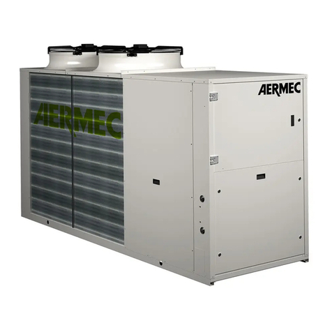
AERMEC
AERMEC Variable Multi Flow ANL Series Installation and maintenance manual
