Hitecsa MINI KRONO 2-i EKWXBAi Series User manual

EKWXBAi
Heat Pump
WATER CHILLERS WITH AXIAL FANS
Range: MINI KRONO2INVERTER
Models: 18i│22i│27i
Cooling capacities: from 18.0 kW to 26.3 kW
Heating capacities: from 21.2 kW to 31.2 kW
INSTALLATION, OPERATION AND MAINTENANCE MANUAL
SOLO
FRIO
IOM_EKWXBAi_18ia27i_207847_190202_EN

Thank you for trusting the Hitecsa Products. Our company has been offering the market an extended range of specialized equipment
for air conditioning and cooling installations for over 35 years. Our approach is based on efficiency, flexibility and on practical solutions.
This has been the hallmark of our product catalogue.
The versatility of our factory allows us to deliver solutions that can meet any requirement and we endeavour solving any problem that
may arise in designing and implementing air conditioning installations.
From all of us at Hiplus Aire Acondicionado, once again, thank you very much.

1
EKWXBAi–MINI KRONO2
REVERSIBLE WATER CHILLERS
AXIAL FANS
IOM_EKWXBAi_18ia27i_207847_190202_EN
INDEX
INDEX ..........................................................................................................................................1
INTRODUCTION..........................................................................................................................3
Name Plate........................................................................................................................4
REGULATIONS AND CERTIFICATIONS....................................................................................5
RULES AND REGULATIONS:.........................................................................................5
SAFETY INSTRUCTIONS ...........................................................................................................6
NOMENCLATURE.......................................................................................................................8
KRONO 2 HE RANGE .................................................................................................................8
TECHNICAL SPECIFICATIONS..................................................................................................9
DIMENSIONS.......................................................................................................................11
REFRIGERATION SCHEME................................................................................................12
TRANSPORT.............................................................................................................................13
INSPECTION AT RECEPTION.............................................................................................13
LIFTING AND HANDLING ..............................................................................................13
STORAGE............................................................................................................................13
INSTALLATION.........................................................................................................................14
INSTALLATION SITE............................................................................................................14
WEIGHTDISTRIBUTION .....................................................................................................14
SERVICE AREA (MM)...........................................................................................................14
UNITSETTLEMENT.............................................................................................................14
INSTALLATION OFWATER PIPES......................................................................................15
SAFETY COMPONENTS................................................................................................15
OTHER COMPONENTS.................................................................................................15
INSTALLATION OF WATER PIPES...............................................................................................16
RISK OF FROST ............................................................................................................16
Glycol additions...............................................................................................................16
Water connections ..........................................................................................................16
Installation LIMITS ..........................................................................................................16
ELECTRICAL INSTALLATION .............................................................................................17
Electrical specifications...................................................................................................17
ELECTRICALWIRING..........................................................................................................17
CONNECTION OF THE pGD CONTROLLER................................................................18
EKWXBAi- MINI KRONO2INVERTER

2
EKWXBAi–MINI KRONO2
REVERSIBLE WATER CHILLERS
AXIAL FANS
IOM_EKWXBAi_18ia27i_207847_190202_EN
OPERATION..............................................................................................................................19
START-UP............................................................................................................................19
ELECTRICAL SET-UP..........................................................................................................19
HYDRONIC SYSTEM...........................................................................................................19
VENTILATION SYSTEM.......................................................................................................19
THERMOSTATAND CONTROL ..........................................................................................20
Mini pGD or pGD1 thermostat.........................................................................................20
KEYBOARD....................................................................................................................20
START SCREEN ............................................................................................................20
MAIN MENU....................................................................................................................21
START-UP......................................................................................................................21
System operating modes change....................................................................................21
Setpoint temperature setting...........................................................................................21
Date and hour setting......................................................................................................22
Time schedule.................................................................................................................22
Configuration of Inputs and Outputs................................................................................23
Alarms.............................................................................................................................24
EC MOTOR FANS .....................................................................................................................27
TROUBLE SHOOTING ................................................................................................................27
ROTATION CAUSED BY AIR FLOW IN THE WRONG DIRECTION.............................28
MAINTENANCE.........................................................................................................................29
CONSERVATION ANDCLEANING......................................................................................29
MAINTENANCE OF THE ECFAN ........................................................................................30
REFRIGERANTCHARGING................................................................................................31
OPTIONS ...................................................................................................................................32
APPENDIX: SAFETY DATA R410A..........................................................................................33
EKWXBAi- MINI KRONO2INVERTER

3
EKWXBAi–MINI KRONO2
REVERSIBLE WATER CHILLERS
AXIAL FANS
IOM_EKWXBAi_18ia27i_207847_190202_EN
INTRODUCTION
Purpose of this Manual
The present manual together with any other technical document such as refrigeration or hydraulic lines
drawings and electrical diagrams among others have been issued to provide the necessary information for
installation, start-up and maintenance of the unit. Therefore it is essential to read the instructions very
carefully. Please contact us if your machine is equipped with an option or any special modification that are
not mentioned in the present manual.
Make sure that all the necessary information for the correct installation of the system is included in the
manuals that have been supplied together with this unit and/or the rest of the indoor units, accessories, etc.
The manufacturer declines anyresponsibility in case of people/animals injuries or material damages resulting
from an incorrect use of the unit and/or non-compliance with these instructions.
In case of different interpretations and/or errors, the priority order of validity of the given documents will be:
1. Name plate of the unit stating the specifications. 2. IOM (the present document), 3. EDM, technical
catalogue, 4. UM user manuals.
Storage of the Manual
This manual and the electrical diagram of the unit must be preserved and remain available to the operator for any further
consultation.
Updating the Data
The continuous improvement in design and performance to which we are committed to gives us the right to modify the
specifications of our products without prior notice.
Electrical Supply
Check that the electrical network features comply with the data shown in the data nameplate of the unit.
Local Safety Regulations
Observe and analyse all the possible causes of accidents that may arise in the place or places of installation of the units,
check all the medium and the tools that will be used, etc. It is not possible to anticipate each one of the potential
circumstances of danger in this manual. Respect the valid local security standards during installation.
Principles of Security on Installation
The unit has been designed and built so that it does not represent any risk to the health and safety of people. Appropriate
solutions for the project have been adopted to eliminate the possible causes of risk in the installation.
Packaging and Replacement of Equipment
The material of the package (plastic bags, insulating materials, nails, etc.) is a potential source of danger.
Consequently, it should be kept out of the reach of children and properly recycled according to the valid
local safety regulations.
Do not mix this product with household waste at the end of its life. Due to the refrigerant, oil and other
components contained in this product, it must be dismantled by professional installers. All the
waste, depending on its nature shall be sent to recycling, composting or treatment plants, or to an
authorized management agency in accordance with the current local legislations.
Utilization
The unit will be used only for the purpose it has been designed for. Any other use does not imply any kind of liability or
responsibility from the manufacturer.
Incorrect Operation
In case of breakdowns or operation faults, turn the unit off.
4
EKWXBAi–MINI KRONO2
REVERSIBLE WATER CHILLERS
AXIAL FANS
IOM_EKWXBAi_18ia27i_207847_190202_EN
INTRODUCTION
Periodic Inspections and Maintenance
Carry out periodic inspections to detect possible damaged or broken parts. If these parts are not repaired,
people injuries or material damages could be caused. Disconnect the power supply of the unit before
carrying out any maintenance operation.
Make sure that the maintenance areas are accessible. If these areas have to be necessarily invaded by
the air supply and/or lateral return ducts, verify that the design of the ducts allows the access to the fans
and that they are not a hindrance when replacing the filters. If that is not possible make sure access is
from the other side.
All operations shall be carried out in accordance with local safety regulations.
Repairing Operations
The reparations shall always and exclusively be completed by trained personnel previously authorized by
the manufacturer and only original spares shall be used. The safety devices of the unit may be damaged
in case of non-compliance with these warnings.
Modifications
The manufacturer will not respond to possible warranty claims and damages of the unit in case of electrical and/or
mechanical modifications. The unauthorized manipulation, reparation or modification of the unit will automatically invalidate
the warranty.
Refrigerant
This product is hermetically sealed and contains R-410A which is a HFC fluorinated greenhouse gas.
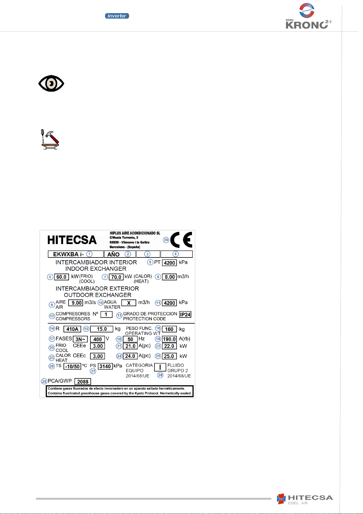
Name Plate
Description of the name plate stuck to the unit.
1. Name of the Unit.
2. Year of production
3. Unit code.
4. Serial Number.
5. Test Pressure, Refrigerant Side.
6. Cooling Capacity in Rated Conditions (EN-14511)
7. Heating Capacity in Rated Conditions (EN-14511)
8. Water Flow in the Indoor Heat Exchanger.
9. Air Flow in the Outdoor Heat Exchanger (“X” If not applicable).
10. Water Flow in the Outdoor Heat Exchanger (“X” If not
applicable).
11. Maximum Operating Pressure on the Refrigerant Side of the
Outdoor Heat Exchanger
12. Total Number of Compressors.
13. Protection Code IP (Dust or water tightness).
14. Type of refrigerant needed for unit operation.
15. Refrigerant charge needed for optimum operation of the unit. In
case of difference with the catalogue value, the value indicated on the
name plate is the most accurate for the particular unit.
16. Total weight of the unit + Option and accessories in operating
conditions.
17. Number of phases (three-phase ± N, single phase, etc.) and
voltage at which this unit must be powered.
18. Frequency of the electrical network to which the machine must
be connected.
19. Maximum starting current (all electrical components running at
maximum current and commissioning of the last stage of
compressors)
20. Performance of the equipment (incl. uprated + options + accessories) in the cooling mode.
21. Maximum operating current in the cooling mode.
22. Unit power input (standard unit operating in rated cold conditions ± optional, etc.)
23. Performance of the equipment + accessories in heating mode.
24. Maximum operating current in the heating mode.
25. Unit power input (standard unit operating in rated heat conditions ± optional, etc.)
26. Lower / higher temperature according to the
27. Maximum permitted Design Pressure (PED).
28. Unit Category (PED) and fluid group (refrigerant)
29. Global warming potential of refrigerant relative to CO2.
30. CE label and number of the notified entity (only for category II or higher).

5
EKWXBAi–MINI KRONO2
REVERSIBLE WATER CHILLERS
AXIAL FANS
IOM_EKWXBAi_18ia27i_207847_190202_EN
REGULATIONS AND CERTIFICATIONS
ISO 9001 CERTIFICATION: HIPLUS AIRE ACONDICIONADO S.L., by endeavouring to always gain the maximum
satisfaction from their customers, obtained the ISO 9001: Quality System for its production activity. That result shows our
continuous determination to improve quality and the reliability of all our products. Our commercial activities, design, raw
materials, production processes and after-sales service represent the means to reach our goal.
CE MARKING: Our products are CE marked according to the essential requirements of the applicable EC directives and
their last modifications and comply with the national legislation of each country.
EUROVENT CERTIFICATION: HITECSA participates in the EUROVENT Certification program. Please check which
models are certified on the web.
RULES AND REGULATIONS:
Commission Regulation (EU) 2016/2281 Ecodesign requirements for energy-related products, with regard to ecodesign
requirements for air heating products, cooling products, high temperature process chillers and fan coil units Text with EEA
(European Economic Area) relevance.
Commission Regulation (EU) No 813/2013 Ecodesign requirements for space heaters and combination heaters (Text with
EEA relevance).
Regulation UNE-EN 14511:2014 Air conditioners, Water Chillers and Heat Pumps equipped with an electrical powered
compressor meant for heating or cooling of premises.
Regulation UNE-EN 14825:2016 Air conditioners, Water Chillers and Heat Pumps equipped with an electrical powered
compressor meant for heating or cooling of premises. Tests and classification completed in partial load conditions and
calculation of the seasonal performance.
Regulation UNE-EN 60204 :2007 Machine safety. Electrical part of the machines.
Directive 2014/68/UE of the European Parliament and of the Council of 15 May 2014 on the harmonisation of the laws of
the Member States relating to the making available on the market of pressure equipment (Text with EEA relevance).

6
EKWXBAi–MINI KRONO2
REVERSIBLE WATER CHILLERS
AXIAL FANS
IOM_EKWXBAi_18ia27i_207847_190202_EN
SAFETY INSTRUCTIONS
Before starting any installation, service or maintenance operation, turn the main power switch off in order
to avoid electrical discharges that may cause personal injuries.
Should it be necessary to open the electrical box in order to get inside the equipment, it is COMPULSORY to plug
the main power cable out prior to this operation. The equipment MUST ALWAYS BE FREE OF VOLTAGE when
opening the electrical box.
It is absolutely forbidden to carry out work on electrical live parts. The protection class of the opened unit is IP00!
Check the safe isolation from the supply by using a two-pole voltage detector.
DANGER
Do not touch or adjust the safety devices inside the unit. For repairs use only original spare parts and install them
properly in the same position where the old parts were fitted.
The installation and maintenance of air conditioning equipment may be dangerous due to the pressure of the
system, the high temperature of some of its parts and the electrical components.
Do not install the unit in an explosive atmosphere.
If the motor of the fan runs independently after the unit has been switched off because it is pushed by airflow for
example, dangerous voltage of more than 50 V may be present in some of the internal connection parts of the
motor. In that case the fan is working as a generator.
When the unit is equipped with EC motors or motors with variable speed control, the ground wire (depending on the
switching frequency, the current source voltage and the motor capacity) is conducting high discharge currents.
Therefore check that the earth grounding is complying with the EN standards even for testing and trial operations
(EN 50 178, Art. 5.2.11). Without grounding dangerous voltages may be present in the motor housing.
The use of capacitors implies a danger of death even after switching the device off in case of direct contact with
conductive parts or with parts that carry voltage due to fault conditions. Removing or opening the housing of the
controller and the terminal box for example is only permitted after the power supply cable has been disconnected
for 3 minutes.

7
EKWXBAi–MINI KRONO2
REVERSIBLE WATER CHILLERS
AXIAL FANS
IOM_EKWXBAi_18ia27i_207847_190202_EN
SAFETY INSTRUCTIONS
Only qualified and trained service staff (technical service) is authorized to carry out installation, commissioning and
maintenance. Unqualified personnel will carry out basic tasks only such as cleaning and replacement of filters, or
filter cleaning (excluding the refrigerant filters), etc…
Prevent access to children to avoid that they play with the equipment.
For all visits, follow carefully all recommended precautions: the instructions recommended in the installation,
operation and maintenance manual, as well as the precautions stated on the stickers placed on the unit. Do not
forget to strictly follow any other legal safety instructions.
DO NOT introduce objects into the air inlets or outlets that might be drawn into the fan, people, etc.
Add antifreeze to the units equipped with water-air, water-water, or refrigerant-water heat exchangers until the
freezing temperature decreases to minimum -2°C (6% when using Ethylene Glycol).
Moreover when the ambient temperature in any part of the installation may reach values lower than 0°C it is
COMPULSORY to protect the unit and the whole installation properly against possible breaks due to frost by
adding additional antifreeze so that the freezing points is 3 grades lower than the minimum temperature that the
ambient temperature may reach. Additional measures may be taken as well such as heating tubes and draining
the unit and the whole installation for water (when the unit will not be uses).
The fan / motor may start and stop automatically due to functional reasons.
After a power failure or a main disconnection an automatic restart of the fan takes place when power supply
returns!
Never approach the fan until it has stopped completely! Beware as it may be rotating even without electric power
but airflow for example.
When the motor is provided with an external rotor, the rotor rotates during operation.
Use safety glasses, work gloves and any other safety accessory that may be necessary for the operation
For brazing operations use a quenching cloth and make sure you have a fire extinguisher close to you.
This product contains fluorinated greenhouse gases. In case of leakage air may be displaced which may cause lack
of oxygen.
The decomposition of fluorinated gases when being burned during brazing operations for example may cause the
presence of highly toxic and corrosive gases.
All the safety recommendations must be followed carefully.
ATTENTION!
The warranty of the unit will not cover the damages caused by frozen water.
A broken exchanger due to frozen water may cause a refrigerant or oil leakage that would
harm the ecosystem.
WARNING!
The responsibility for all personal and material damages caused by an unexpected or
inappropriate use will be born by the person or the operating company of the unit and not by the
manufacturer.
WARNING!

8
EKWXBAi–MINI KRONO2
REVERSIBLE WATER CHILLERS
AXIAL FANS
IOM_EKWXBAi_18ia27i_207847_190202_EN
NOMENCLATURE
MINI KRONO INVERTER Range
E
K
W
X
B
A
i
- 27 i
Water Chiller KRONO –KRONO2
Internal water exchanger (plates)
Air condensed with axial fan
Heat pump
R410A
Inverter compressor
Maximum heating capacity (kW)
KRONO 2 HE RANGE
KRONO 2 HE range WATER CHILLERS
VARIABLE CAPACITY and REVERSIBLE CYCLE with EXTERNAL AXIAL FAN
EKWXBAi
EKWXBA HE
38.2
44.2
47.2
55.2
59.2
67.2
18 i
22 i
27 i
EKWXBA HE
75.2
EKWXBA HE
95.2
109.2
EKWXBA HE
121.4
132.4
171.4
EKWXBA HE
193.4
207.4

9
EKWXBAi–MINI KRONO2
REVERSIBLE WATER CHILLERS
AXIAL FANS
IOM_EKWXBAi_18ia27i_207847_190202_EN
TECHNICAL SPECIFICATIONS
MINI KRONO INVERTER RANGE
18i
22i
27i
CAPACITIES
COOLING CAPACITY (1)
AC application = Water temperature 12/7°C –Air temp. 35°C
Maximum cooling CAPACITY
kW
18.0
21.7
26.3
Total Absorbed Power
kW
8.7
10.3
13.2
EER
2.06
2.10
2.00
Evaporator water flow
m³/h
3.0
3.6
4.4
Available pressure (with pump)
kPa
186
169
146
SEER
3.93
4.14
3.97
ηs cooling
%
154.3
162.6
155.6
HEATING CAPACITY (2)
Application IT = Water Temp. 40/45°C –Air Temp. 7°C b.s./6°C b.h.
Heating CAPACITY
kW
21.2
26.4
31.2
Total Absorbed Power
kW
10.5
11.9
13.9
COP
2.0
2.2
2.2
Water flow
m³/h
3.9
4.8
5.6
Available static pressure
kPa
167
140
109
HEATING CAPACITY
Application LT = Water Temp. 30/35°C - Air Temp. 7°C b.s./6°C b.h.
Heating CAPACITY
kW
22.0
27,2
32,3
Total Absorbed Power
kW
8.1
10.0
11.8
COP
2.7
2.7
2.7
Water flow
m³/h
3.9
4.8
5.6
Available static pressure
kPa
161
130
99
SCOP
3.2
3.2
3.2
ηs heating
%
125.0
REFRIGERATION CIRCUIT
REFRIGERANT
Number of circuits
-
1
Type of refrigerating gas
-
R-410A
GWP (3)
-
2088
Refrigerant charge (without any option)
kg
7.5
9.2
9.3
COMPRESSORS
Type
-
Scroll Inverter BLDCM
Number total of compressors
1
Number of power stages
-
Variable 20-120rps
Oil type
FV50S
Oil volume
L
1.7
2.3
CIRCUIT SAFETY DEVICES
Expansion device
Electronic expansion valve
Filter dryer
Biflow
ELECTRICAL DATA
Power supply
V / ~/Hz
400 / 3N / 50
Maximum current
A
19
25
27
Start current
A
Soft start
Main switch
A
63
1. Calculated according to the UNE-EN-14511-2013 standard for the following conditions: inlet water temperature
12ºC, water outlet 7ºC and outdoor air temperature 35ºC.
2. Calculated according to the UNE-EN-14511-2013 standard, for the following conditions: 40ºC, water outlet 45ºC,
outdoor air temperature 7ºC B.S. and 6ºC B.H..
3. GWP: Global warming potential (climatic) of 1 kg of greenhouse gas relative to 1 kg of CO2, calculated in terms
of 100-year warming potential.

10
EKWXBAi–MINI KRONO2
REVERSIBLE WATER CHILLERS
AXIAL FANS
IOM_EKWXBAi_18ia27i_207847_190202_EN
TECHNICAL SPECIFICATIONS
SERIE MINI KRONO INVERTER
18i
22i
27i
OUTDOOR EXCHANGER
Type
COIL of finned copper tubes
Number
1
OUTDOOR FAN
Type
-
AXIAL with EC motor
Total number
-
1
Maximum air flow
m3/h
19500
18500
18500
Available static pressure
Pa
0
Nominal capacity
kW
1.95
Maximum current
A
3.3
WATER CIRCUIT
Connection type
GROOVED –VICTAULIC TYPE
Connection outer diameter
"
1 1/2 ''
Minimum water volume
l
70
80
100
Minimum water flow
m³/ h
2.7
3.2
3.9
4.4
5.3
6.5
Maximum water flow
m³/ h
WATER PUMP
Number
1
Maximum operating current
A
1.6
OPTION, WITHOUT PUMP
NO
OPTION, HIGH PRESSURE PUMP
YES
OPTION, RESERVE PUMP
YES
INDOOR EXCHANGER
Type
PLATES (Water/Refrigerant)
Quantity
-
1
Antifrost resistance
W
100
HIGH PRESSURE CIRCULATING PUMP
(OPTION)
Number
1
Maximum operating current
A
2.37
Maximum available pressure (AC application)
kPa
278
260
235
Maximum available pressure (IT application)
kPa
258
229
196
Maximum available pressure (LT application)
kPa
252
218
185
0
SOUND LEVEL
Sound power (Lw)
dB(A)
78
0
DIMENSIONS AND WEIGHT
Length
mm
1214
Width
mm
1083
Height
mm
1483
WEIGHT (Without options or charge)
kg
365
381
386
TOTAL WEIGHT incl. all options
kg
419
435
441

11
EKWXBAi–MINI KRONO2
REVERSIBLE WATER CHILLERS
AXIAL FANS
IOM_EKWXBAi_18ia27i_207847_190202_EN
TECHNICAL SPECIFICATIONS
DIMENSIONS
1. External probe
2. Electrical box
3. Main switch
4. Electrical connection inlet
5. Water outlet –Victaulic connection 1 1/2”
6. Water inlet –Victaulic connection 1 1/2”

12
EKWXBAi–MINI KRONO2
REVERSIBLE WATER CHILLERS
AXIAL FANS
IOM_EKWXBAi_18ia27i_207847_190202_EN
TECHNICAL SPECIFICATIONS
REFRIGERATION SCHEME
1 - Compressor.
2 - 4-way valve.
3 - Electronic expansion valve.
4 - Check valve.
5 - Filter.
6 - Liquid tank.
7 - Plate heat exchanger.
8 - Suction accumulator.
9 - EC external fan
10 - Condensing coil
B1 - Circulating pump
HP - High pressure switch
HPS - High pressure sensor
LPS - Lower pressure sensor
TD - Discharge temperature
TE - Outdoor temperature
TS - Suction temperature
TEA - Water inlet temperature
TSA - Water outlet temperature
VS - Safety valve
OPTIONS:
PD - DIFFERENTIAL PRESSURE SWITCH
Vc - MANUAL DAMPER VALVE
VEx - EXPANSION TANK
Vf - FLAP VALVE
FM - FLOWMETER
ACCESSORIES:
FS - FLOW SWITCH
FT -WATER FILTER

13
EKWXBAi–MINI KRONO2
REVERSIBLE WATER CHILLERS
AXIAL FANS
IOM_EKWXBAi_18ia27i_207847_190202_EN
TRANSPORT
INSPECTION AT RECEPTION
It is advisable to examine the equipment carefully upon reception.
Check that the equipment has not been damaged during transport and that it is complete with all the parts specified
in the order and/or the options stated in the order. If this is not the case please contact the transport company
immediately (within 48h).
Verify the correct voltage of the nameplate and make sure it is in accordance with local power supply.
In case of any flaw or anomaly detected, please contact HITECSA.
LIFTING AND HANDLING
Before moving the unit, make sure that all panels are fixed properly.
Raise and put the equipment down carefully.
Do not tilt the unit more than 15 degrees during transportation.
Always transport the unit in its original packaging to the place of installation.
All units come with a particular rigging diagram of that model similar to the one shown below. Be sure to hoist the machine
through the points indicated in the diagram.
STORAGE
If the equipment is going to be stored before the installation, please follow the following instructions in order to avoid
damages, corrosion or deterioration:
Move the equipment carefully.
Do not place the unit in places exposed to ambient temperatures above 50ºC and preferably keep the unit away from
direct sunlight.
Avoid placing the unit with plastic wrapping protection under the sun as the pressure of the circuits could reach values
that could lead to the activation of the safety valves.
Moreover, with decreasing temperatures water condensation may occur inside the machine and the plastic wrap.
Avoid placing other objects on top of the unit (unless this is done within the limits of the overlap planes indicated on the
packaging, etc. Follow these indications).
Avoid prolonged storage before installation, water penetration, dust and objects in general due to invasion or biological,
meteorological and/or human impacts.
Minimum storage temperature: 5ºC.
Maximum relative humidity: 90%.
The equipment warranty will not cover any damage caused by frozen water.
WARNING

14
EKWXBAi–MINI KRONO2
REVERSIBLE WATER CHILLERS
AXIAL FANS
IOM_EKWXBAi_18ia27i_207847_190202_EN
INSTALLATION
INSTALLATION SITE
Consult and respect the rules and local regulations which regulate the installation of air conditioning systems.
Choose a site without dust and debris.
Respect the appropriate service area for the equipment that is to be installed.
Verify that the ground or structure on which the unit will be installed is able to support its weight in operation.
Fit shock absorbers throughout the installation to prevent the transmission of noise and vibration.
Check that the direction of the sound level is not going to disturb anyone.
WEIGHT DISTRIBUTION
Standard equipment
Equipment fitted with all the options
WEIGHT DISTRIBUTION (kg)
MODEL
R1
R2
R3
R4
Total
18i
89
110
73
93
365
22i
92
112
79
98
381
27i
93
114
79
100
386
WEIGHT DISTRIBUTION (kg)
MODEL
R1
R2
R3
R4
Total
18i
107
111
99
102
419
22i
111
114
104
106
435
27i
114
116
104
107
441
SERVICE AREA (MM)
Respect the following dimensions to make sure the
equipment works properly.
UNIT SETTLEMENT
The bed frame shall be strong enough to support the unit
weight and garanty the even distribution of the weight.
Make sure that after settlement the unit drain is working
properly.
Shock absorbers shall be used to avoid the transmission
of noise and vibrations.

15
EKWXBAi–MINI KRONO2
REVERSIBLE WATER CHILLERS
AXIAL FANS
IOM_EKWXBAi_18ia27i_207847_190202_EN
INSTALLATION
INSTALLATION OF WATER PIPES
The selection and installation of the components of the installation must be carried out by a qualified installer, respecting
the current legislation at the place of work and rules of good practice.
The design and calculation of pipes shall be carried out in such a way that the pressure drop of the installation never
exceeds that which can overcome the pump built into the unit. In addition, a poor design of the pressure drop of the branch
pipes that go to the indoor units can cause the malfunction of some of them.
SAFETY COMPONENTS
The installation of the following safety devices is MANDATORY when these elements ARE NOT included as standard
features. Not complying with this condition will entail the LOSS OF WARRANTY.
Water filter
At the water inlet of the unit, to protect the heat exchanger or other critical components from obstructions and/or clogging.
Flow switch or differential pressure switch
Protection of the water exchanger against breakage due to insufficient water flow, which can lead to total disabling of the
equipment. In case when there are more than one plate heat exchanger each of them shall be protected individually.
It is mandatory to install the flow switch at the water outlet of the machine with a straight horizontal section of 6 Ø (inlet)
and 5 Ø (inlet) horizontal length without section changes to ensure that the water/liquid flow regime is similar. In case of
using flow switches that have not been supplied by HITECSA, please follow the manufacturer’s instructions making sure
that the above mentioned lengths are not reduced.
OTHER COMPONENTS
Shut-off valves
Installed at the inlet and the outlet of each component, they allow to carry out the maintenance operations without having
to empty the installation.
Thermometers and pressure gauges
Installed at the inlet and the outlet of the main elements. They make maintenance and control operations easier.
Air release valves
Installed at the highest points of the installation. They enable air drainage of the circuit.
Drainage valves
Install them at all the low points to empty the circuit.
Supports
The weight of the pipes must not be supported by the connections of the unit. Therefore supporting brides shall be used.
Expansion vessel
Maintains the correct pressure of the installation, we recommend filling at 2.15 bar, when the water temperature varies from
cold to pump and vice versa. The expansion vessel has to bedimensioned according to the water content of the installation.
In special circumstances it may be necessary to install one or more additional vessels even tif the unit already is equipped
with one.

16
EKWXBAi–MINI KRONO2
REVERSIBLE WATER CHILLERS
AXIAL FANS
IOM_EKWXBAi_18ia27i_207847_190202_EN
INSTALLATION
INSTALLATION OF WATER PIPES
RISK OF FROST
If the unit or the water installation are exposed to temperatures around 4°C it is necessary to take the appropriate measures
against the risk of frost.
For example:
Mix the water of the installation with glycol.
Protect the pipes with heating cables placed under the insulation lining.
Empty the installation and control at the same time that:
There are no closed valves that may retain water even after draining the installation.
There are no low spots where water may stagnate even after draining; if necessary proceed to purging the installation.
Glycol additions
Keep in mind that the use of glycol solutions increases the pressure drop and reduces the unit performance.
Make sure that the type of glycol you will use is compatible with hydraulic circuit components (pumps, filters, etc.) and that
it is a non-corrosive product.
PROPORTION OF THE WATER-GLYCOL MIXTURE
TARGET FREEZING TEMPERATURE
0ºC
-2ºC
-5ºC
-10ºC
-15ºC
-20ºC
-25ºC
-30ºC
ETHYLENE GLYCOL
0%
6%
14%
24%
31%
36%
41%
45%
PROPYLENE GLYCOL
0%
7%
15%
25%
33%
39%
44%
48%
Consider security margins when adding Glycol.
Water connections
The units are delivered with Victaulic type flanges.
Connection is made by joining both grooved tubes (unit with the installation) by using the rubber
O-ring and the delivered fastening flange.
A gas male thread tube adaptor is available as an option.
Installation LIMITS
18i
22i
27i
Minimum water flow
m3/h
2,7
3,2
3,9
Maximum water flow
m3/h
4,4
5,3
6,5
Minimum water volumen
L
70
80
100
Mínimum water temperature (6% Ethylene glycol)
°C
2
Minimum water temperature (20% Ethylene glycol)
°C
-5
Minimum water temperature (30% Ethylene glycol)
°C
-10
Minimum water temperature (35% Ethylene glycol l)
°C
-15
EXPANSION TANK
L
12
Maximum water volume (7-50°C)
L
490
Maximum water volume (4-55°C)
L
410
Expansion coefficient Water (between 7-50°C)
ΔV/V
0,0121
Expansion coefficient Water (between 4-55°C)
ΔV/V
0,0145
50% absorbtion capacity in the EXPANSION TANK.
Add to the water minimum 6% Ethylene Glycol (7% Propylene Glycol).

17
EKWXBAi–MINI KRONO2
REVERSIBLE WATER CHILLERS
AXIAL FANS
IOM_EKWXBAi_18ia27i_207847_190202_EN
INSTALLATION
ELECTRICAL INSTALLATION
Electrical specifications
ELECTRICAL SPECIFICATIONS
MODELS
18-i
22-i
27-i
Power supply
V / ~/Hz
400 / 3N / 50
Maximum current
A
19
25
27
Start current
A
Soft start
Main switch
A
63
63
63
Select the connection cable section according to the voltaje drop limits defined by the local Low Voltage Electrical
Regulations.
Prepare a good grounding (according to the current regulations). Since the machine is equipped with frequency converters
we recommend you use differentials with protection against harmonics (superimunized).
ELECTRICAL WIRING
The unit power supply should be within 10% of volts indicated on the unit nameplate. Damage caused by the start-up
of the unit in an incorrect voltage line is not covered by the Hitecsa’s warranty.
Always refer to the unit wiring diagram when making electrical connections.
Make sure that the compressor crankcase heater can be energized before unit starts.
The installer shall use the protection line devices according to the current regulations.
The interconnecting wires have to be placed in the protection tube or electrical cable conduits, cable trays. etc.
D Put the main power switch in the OFF position before starting any type of operations.
WARNING!
1. Main power upply 400/3/50 + neutral + Grouding
2.
Main switch
3. Mini PGD Controller (Refer to the control scheme)

18
EKWXBAi–MINI KRONO2
REVERSIBLE WATER CHILLERS
AXIAL FANS
IOM_EKWXBAi_18ia27i_207847_190202_EN
INSTALLATION
CONNECTION OF THE pGD CONTROLLER
The mini pGD terminal is the standard user control display (pGD1 available as an option).
Connection to the central unit’s board (µPC) with a 6 wire-telephone cable.
For distances longer than 50 m and shorter than 200 m intersperse with TCONN bypass
(through 2 shielded and twisted pairs).
This manual suits for next models
3
Table of contents
Other Hitecsa Chiller manuals


Popular Chiller manuals by other brands

Skope
Skope SERENE SC112G Service manual

lancer
lancer S8H Installation, operation & service manual

Trane
Trane Arctic Manhattan Gen II Installation, operation and maintenance

Trane
Trane PRGD series Installation, operation and maintenance

USA Lab
USA Lab UC Series manual

Robur
Robur ACF 60-00 Installation, use and maintenance manual

Daikin
Daikin EWLD120MBYNN Operation manual

Thermo
Thermo NESLAB RTE Series Installation, Operation, Basic Maintenance

Iom
Iom AQCL 25 Installation and maintenance manual

Dunham-Bush
Dunham-Bush WCFX-E Series manual

Daikin
Daikin WCT Installation, operation and maintenance manual

Electrolux
Electrolux 10 GN 1/1 Brochure & specs


