Hitecsa EKWXA User manual
1
04.14 000000 Rev. 000
INSTALLATION, OPERATION AND MAINTENANCE MANUAL
Modelos 801.1 │1001.1 │1201.1 │1501.1
Cooling Capacities: 26,0kW a 40,0kW
Pot. Caloríficas: 28,1kW a 43,1kW
11.15 207443 Rev102
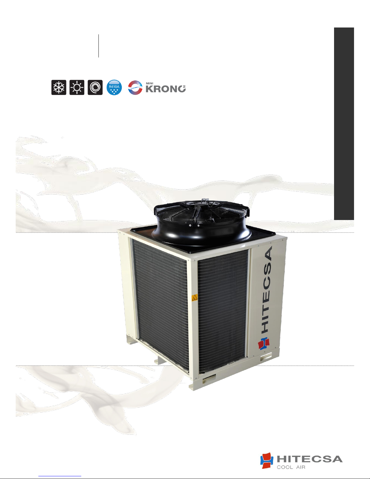
EKWXA EKWXBA
AIR COOLED WATER CHILLERS –AXIAL FANS
Cooling only
Sólo frío
With Heat pump
Bomba de calor

2
AIR COOLED WATER CHILLERS –AXIAL FANS
EKWXA/EKWXBA
11.15 207443 Rev104
TABLE OF CONTENTS
INTRODUCTION .....................................................................................................................................3
GENERAL DESCRIPTION ............................................................................................................................3
SAFETY PRECAUTIONS ...........................................................................................................................5
GENERAL CHARACTERISTICS ..................................................................................................................6
COMPONENT DESCRIPTIONS ...................................................................................................................6
VERSIONS .................................................................................................................................................9
ACCESSORIES /OPTIONALS ......................................................................................................................9
ELECTRICAL DATA...................................................................................................................................10
APPLICATION LIMITS ..............................................................................................................................11
UNIT RECEPTION..................................................................................................................................12
INSPECTION UPON ARRIVAL...................................................................................................................12
STORAGE ................................................................................................................................................12
RIGGING .................................................................................................................................................12
INSTALLATION LOCATION ......................................................................................................................13
UNIT SETTLEMENT..................................................................................................................................13
SERVICE AREA.........................................................................................................................................13
WEIGHT DISTRIBUTION (KG) ...................................................................................................................14
REFRIGERANT CHARGE ........................................................................................................................15
COMPRESSOR LUBRICANT......................................................................................................................15
START UP .............................................................................................................................................16
LCX CONTROL .........................................................................................................................................16
MCX CONTROL (OPTIONAL UPGRADE)...................................................................................................17
MAINTENANCE ....................................................................................................................................18
APPENDIX: SAFETY CHART R410A ........................................................................................................18

3
AIR COOLED WATER CHILLERS –AXIAL FANS
EKWXA/EKWXBA
11.15 207443 Rev104
INTRODUCTION
GENERAL DESCRIPTION
► Manual purpose
This manual and the 88610 and 88611 documents have been created to guide in the correct installation,
start-up and maintenance of the unit. For this reason is essential to read the instructions paying due
attention. The manufacturer waives any liability, for possible damages on persons or stuff, as a
consequence of an improper use of this unit and/or non-compliance with these instructions.
► Manual preservation
This manual and the electric diagram of the unit must be retained and remain available to the operator for
further consultation.
► Local safety standards
Follow the local security standards during installation.
► Electrical network
Check that electrical network features are in accordance to data shown in the data nameplate of the unit.
►Packaging
Packaging material (plastic bags, cellular polystyrene, cloves, etc.) constitutes a dangerous source, for
that it should be kept out of the reach of children and recycled correctly according to local security
standards.
► Maintenance
Before executing any maintenance operation, cut off the unit power supply. Operations have to be carried
out following local security standards.
► Periodic inspections
Carry out periodic inspections to detect possible damaged or broken pieces. If they are not repaired it
could result in damage to people or stuff.
► Incorrect operation
In case of breakdowns or operation faults, turn off unit.
► Repairs
Reparations should be always realized for trained personal authorized by the manufacturer using original
spares. Failure to comply with these warnings could affect the safety features of the unit.
► Modifications
All manufacturer responsibility is declined when the warranty has been expired in case of electrical and/or
mechanical modifications. Alterations in general not expressly allowed and not respecting what is
instructed here, they cause the warranty expiration.
► Use
The unit will only be used for the purpose it has been conceived. Any other use does not imply any kind of
compromise or liability for the manufacturer.
4
AIR COOLED WATER CHILLERS –AXIAL FANS
EKWXA/EKWXBA
11.15 207443 Rev104
► Principles of security on installation
The unit is designed and built so that a risk to health and security for people are not supposed. Suitable
project solutions have been adopted to delete possible causes of risk in the system.
► Data actualization
Continuous improvements to the product may determine variations in the data given even without notice
by the manufacturer.
► Standards and certifications
CE QUALIFICATION: Our units have CE brand in accordance with the expected for the relevant
community directive, and its last modifications, as well as for each country's national legislation.
5
AIR COOLED WATER CHILLERS –AXIAL FANS
EKWXA/EKWXBA
11.15 207443 Rev104
• Installation and maintenance of air conditioning equipment can be dangerous because the liquid
circulating through the system is pressurized, some elements work at high temperatures and includes
electrical components.
•Only qualified and trained service personnel should install, start up and do maintenance tasks on this air
conditioning equipment.
• During every visit follow recommendations from the Installation Operation Maintenance manual, pay
attention to the indications shown on unit’s stickers and take safety precautions according general
legislation.
• Strictly follow all safety codes.
• Use safety glasses, work gloves and any other work safety accessory.
• For brazing operations use a quenching cloth and have a fire extinguisher at a close distance in case of
emergencies.
• When repairing the unit use only original spare parts and install them properly in the same place and
position where the old parts were located.
• Do not install the unit in explosive atmosphere.
SAFETY PRECAUTIONS
Before starting installation, service or maintenance turn off system’s main power
switch to avoid electrical shock which may result in personal injury.
WARNING!
6
AIR COOLED WATER CHILLERS –AXIAL FANS
EKWXA/EKWXBA
11.15 207443 Rev104
EKWXBA compact units are reversible air cooled water / heat water production and designed for its
installation outdoor. It is provided with R-410A refrigerant charge already for its installation. These units
are manufactured under strict quality control throughout the whole process and when they are finished
they are tested in the factory, checking the correct working of all their components.
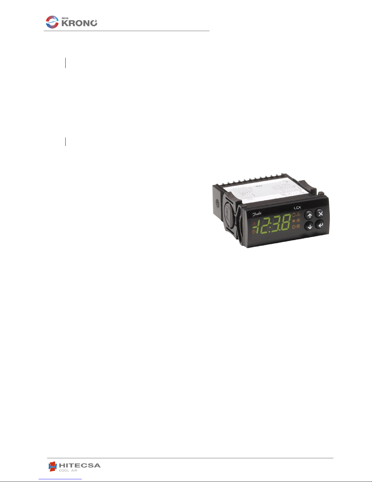
1. Remote Control System.
LCX Control System
- Main on-off switch.
- Device control phase sequence.
- Monopolar magnetothermal of control protection.
- Monopolar magntothermal of protection of
compressors crankcase resistors.
- Safety and isolation transformer for 24
Vac power to control itself.
- Contactors for compressors and outdoor fans.
- Controller with LED display of 3 ½ digits and 8 icons
to show all the information on the display itself.
- Display by default: Outdoor water temperature.
- Self-diagnostics with alarm code display.
Main Functions of the Control System
- Regulation Water temperature.
- Counting the hours of operation for maintenance of compressors and pumps if the unit is built with this
optional.
- Visualization of inlet and outlet water temperatures on the unit and Condenser and Evaporation
pressures.
- Timings of starts of compressors.
- Security protection of High Pressure.
- Compressors Electronic protection.
- Outdoor fans protection.
- Water flow protection.
- Intervention for antifreeze security.
- ON/OFF remote.
- Remote changing of operation mode Cool/Heat.
- Condensation and evaporation pressure control with 2 ventilation stages..
- Reversible valve of cycle inversion (Only for het pump models).
- Discharge maneuver. Start and ending of Pressure discharge. Control of run times between defrosts.
COMPONENT DESCRIPTIONS
GENERAL CHARACTERISTICS

7
AIR COOLED WATER CHILLERS –AXIAL FANS
EKWXA/EKWXBA
11.15 207443 Rev104
MCX Control System (OPTIONAL UPGRADE)
- Controller is composed of user interface and electronic board.
- Power supply : 20/30 Vdc –24 Vac.
- Panel mounting type.
- Screen with display that allows the inputs and outputs to be
visualized.
- Operating mode : 2 compressors, cooling only and heat pump.
- Defrosting by pressure transducers.
- Management of water circulating pump and hydraulic module.
- Clock programming.
- Programmable controller with 3 access levels: User,
Maintenance and Manufacturer.
Main Functions of the Control System
- Regulates wáter temperature
- Service hour counter for compressors and wáter pumps (optional)
- Intake and outlet water temperature reading displays, as well as, pressure reading displays in evaporator
and condenser stages
- Compressor start timers
- Pressure overload safety protection
- Electronic compressor protection
- External fan protection
- Water flow protection
- Anti-freeze active protection
- Remote ON/OFF
- Remote COOL/HEAT mode toggle
- Condensing and evaporating pressure control by incorporating 2 ventilation stages
- Check valve for cycle reversion (only available for Heat Pump units)
- Anti-frost feature. Anti-frost start and stop settings through pressure readings.
- Anti-frost duration time control.
2. Compressor
Hermetically sealed, alternative compressor with wide operation limits. Equipped with thermal protection, -
any other additional protection is not needed-, it includes its oil charge for the perfect lubrication and
internal shock-absorbing system. The compressor is mounted on the base with antivibration supports and
it is acoustically isolated, guaranteeing a silent and vibration-free operation.
3. Outdoor coils
Coils built with seamless copper tubes and expanded in aluminum fins. They incorporate a distributor with
neck and calibrated orifice (nozzle) to improve gas distribution in Cool mode.
4. Refrigerant-water heat exchanger
Stainless steel plate heat exchanger (AISI 316) welded with a bronze based technique. It’s perfectly
isolated with insulating material to avoid thermal exchange with its surroundings. It incorporates a resistor
to frost protection mode to avoid dangers of breaking by water freezing in case of lack of water flow.
5. Motorfan
Mounted on a square-based embouchure; with a circular opening, which is ideal for optimal aerodynamic
performance of air flow supplied by the fan. Weatherproof completely sealed and permanently lubricated.
They consist of aluminum blades designed for low noise, inserted into the outdoor rotor of a high-efficiency
motor with IP-54 protection and Class F coil insulation. Internal thermal sensors have built-in for their
protection and an external safety grate.
8
AIR COOLED WATER CHILLERS –AXIAL FANS
EKWXA/EKWXBA
11.15 207443 Rev104
6. Expansion devices
The unit is equipped with thermostatic expansion valves with MOP on in the inlet of plate heat exchanger
for functioning in refrigeration mode. The expansion in the outdoor coil, when necessary (functioning in
heating mode), is done through orifice (nozzle).
7. High pressure pressostat
Security pressostat connected to the compressor output (maximum pressure point) manual reset. Shut off
is calibrated to a pressure of 42 bars.
8. Dehydrator filter
Bidirectional type filters are mounted in the liquid line. It has a desiccant solid core that minimizes vibration
and friction during operation, as well as absorbing the excess moisture and filter possible impurities.
9. Liquid container
It is, basically, a tank to hold the difference of refrigerant charge required by the unit to operate between
Cooling/Heating.
10. Check valves
Only in heat pump units to carry out the bypass to the expansion system of the secondary exchanger
block. In cooling mode it carries out the bypass to the coil, in heating mode, to the expansion valves.
11. Sheet structure
The unit’s structure is weather resistant and it consists of galvanized steel sheet applying an oven-cured
painting process by polymerizing paint providing excellent coating to whole set and, especially, in edges
and corners. The freestanding base is built with high stiffness steel and the rest of the structure is made of
galvanized steel. The design is intended for easy maintenance. The color of the finished set is RAL 1013.

9
AIR COOLED WATER CHILLERS –AXIAL FANS
EKWXA/EKWXBA
11.15 207443 Rev104
STANDARD
Outdoor fans of motors of 6 poles and without compressor isolation
IC
Outdoor fans with 6 poles and with compressor isolation
Type 1: Basic Compressor Isolation [Sound level reduction 2 dB (A)]
Type 2: “Low Noise” Compressor Isolation [Sound level reduction 6 dB (A)]
SIL
Outdoor fans of Bionic Profile of 8 poles and with Compressor Isolation
Type 1: Basic Compressor Isolation [Sound level reduction 3 dB (A)]
Tipo 2: “Low Noise” Compressor Isolation [Sound level reduction 8 dB (A)]
SS
Electronic Fans of Bionic Profile and Compressor Isolation “Low Noise”
CONDENSATION CONTROL
STANDARD, IC and SIL: Outdoor fans AC with variable speed
SS: Speed regulation standard incorporated
EMPOWERED FAN
Incorporation of Electronic Fans EC of bionic profile with more available pressure
This accessory includes Condensation Control of the Unit.
SOFT STARTER
Soft Starters to minimize the intensity peaks at the start of the compressor
ELECTRONIC EXPANSION
Expansion by Electronic Injection valve
HYDRONIC KIT
Option 1: Pumop + Container + Expansion vessel
Option 2: Pump + Expansion vessel
WATER MANOMETER
Manometer incorporation for pressure reading of inlet and outlet water
VICTAULIC
Outdoor Connections of type VICTAULIC Inlet Water
AGRESSIVE
ENVIRONMENTS
Coils coated with Blycol of finned package
Coils with Aluzinc fins
Coils with copper fins
COIL PROTECTIONS
Incorporation of grilles as a protection to avoid bumps in condenser coils
SUPERVISION
External supervision system
MANAGEMENT OF
SEVERAL UNITS
Modular control system via master/slave
*Apart from this options consult our Commercial Department for any other configuration or function not described as available.
ACCESSORIES / OPTIONALS
VERSIONS
10
AIR COOLED WATER CHILLERS –AXIAL FANS
EKWXA/EKWXBA
11.15 207443 Rev104
• The electrical power supply to the unit must be within the 10% of the voltage indicated on the nameplate.
Unit start-up at incorrect voltage is not covered by our guarantee.
• When making electrical connections always use unit wiring diagram.
• Be sure that compressor crankcase heater is energized before unit start.
• The installer has to install line protection elements according to local laws.
• The interconnecting wires have to be in protection tube or inside groove channel.
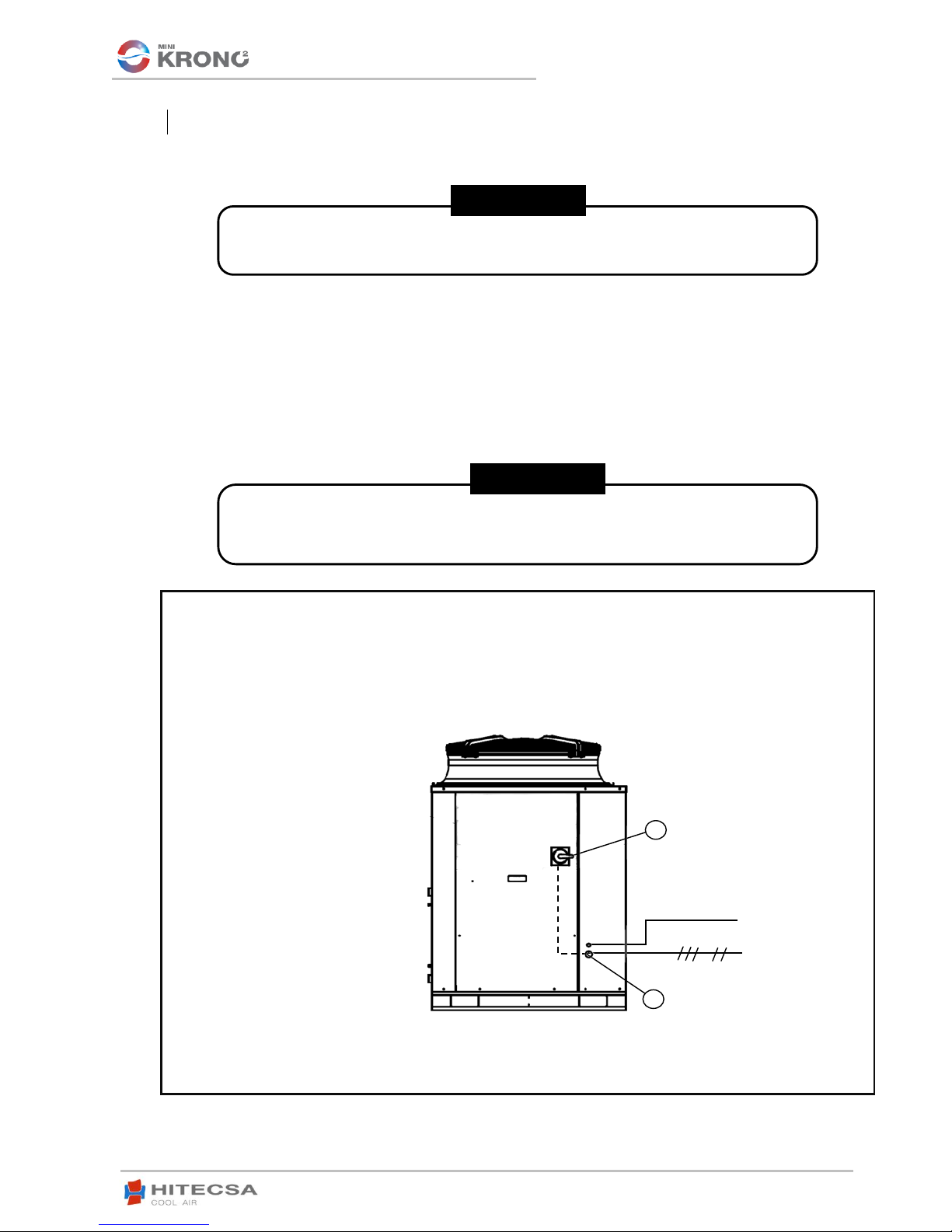
ELECTRICAL DATA
Before starting any type of operation switch off main power switch.
1. Main power supply 400/3/50 + neutral + ground
2. Main power switch
1
2
L1 L2 L3 N T
It is mandatory to install flow switch at the machine water inlet and with previous straight
section of 1,5m without changes in cross section to assure the water or fluid is laminar.
Failure to comply with this causes loss of the equipment warranty.
CONTROL MANEUVER
WARNING!
WARNING!
11
AIR COOLED WATER CHILLERS –AXIAL FANS
EKWXA/EKWXBA
11.15 207443 Rev104
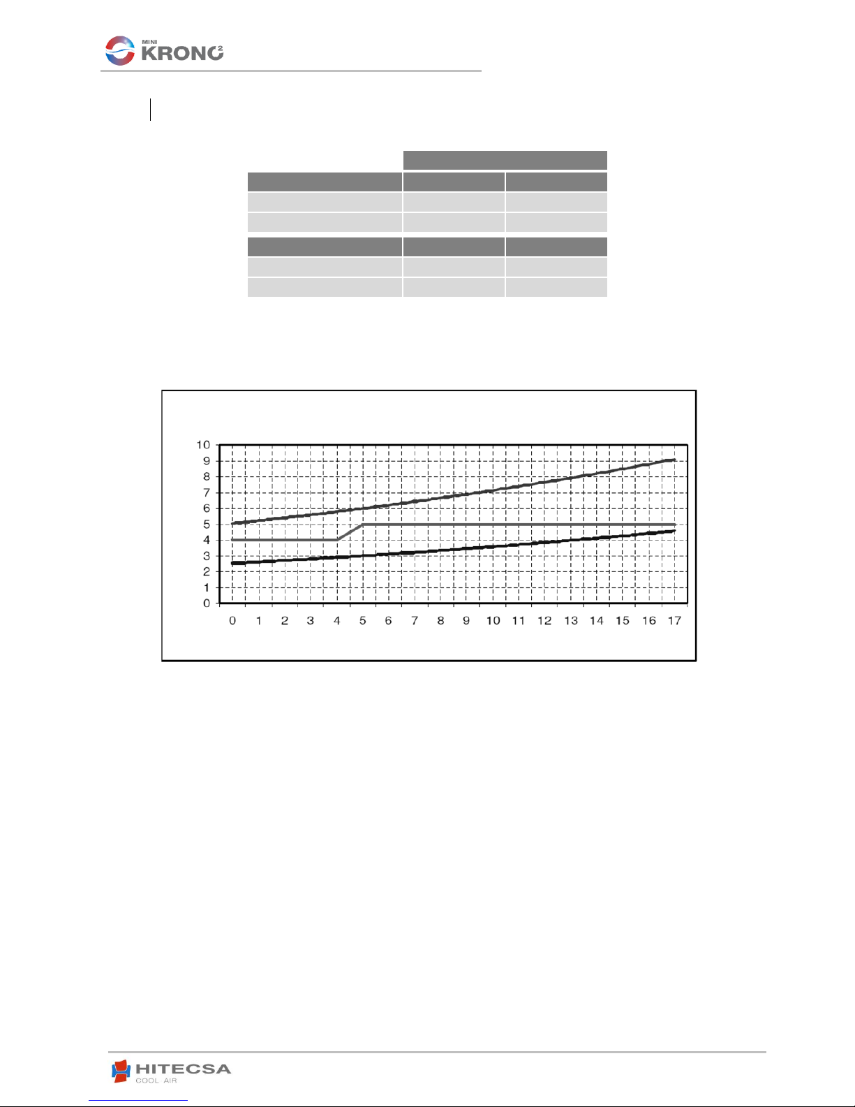
APPLICATION LIMITS
TEMPERATURE
COOLING CYCLE
MÍN.
MÁX.
Outgoing chilled water
5ºC*
16ºC
Outdoor air dry bulb
19ºC**
46ºC
HEATING CYCLE
MÍN.
MÁX.
Outgoing hot water
35ºC
55ºC
Outdoor air water bulb
-10ºC
18ºC***
*For lower temperatures it is necessary to use water glycol mixture.
** For lower temperature use optional low ambient control.
***For lower temperature use optional evaporating pressure.
EVAPORATOR OPERATING LIMITS
Inlet water temperature
Water I/O differential

12
AIR COOLED WATER CHILLERS –AXIAL FANS
EKWXA/EKWXBA
11.15 207443 Rev104
• It is advisable to examine carefully the unit upon receipt.
• Inspect equipment received for damage or missing element. If units are damaged or shipment is
incomplete, immediately file the claim with the transport company. (Within the first 48h)
• Check if unit nameplate voltage is correct and agrees with local power supply.
• In case of detecting any damage or anomaly it is recommended to contact our customer support.
If the unit is to be stored before installation, several precautions must be kept to avoid any damages,
corrosion or any other type of deterioration:
• Do not store the unit in locations with temperatures over 50ºC and preferably without exposure to direct
sunlight.
• Minimum storage temperature: -10ºC
• Maximum humidity: 90%
Moreover it is recommended:
- Move it carefully
- Avoid placing other objects on the unit (Unless this is done within the overlay limits indicated in the
packaging)
- Avoid placing the unit with heat shrink protection under the sun, as the pressure of the circuits might
assume values that could lead to activation of the safety valves
• Before moving the unit be sure that all units panels are well fixed.
• Raise and set down the equipment carefully.
• Never tilt the unit more than 15 degrees during transportation (Fig. 2).
• When lifting the unit ensure that it is balanced and steady, keep in mind that the heaviest part is where
the compressor is installed.
• Always transport unit to installation place in original packaging.
RIGGING
STORAGE
INSPECTION UPON ARRIVAL
UNIT RECEPTION

13
AIR COOLED WATER CHILLERS –AXIAL FANS
EKWXA/EKWXBA
11.15 207443 Rev104
• Check if construction is able to support unit weight.
• Check that the service area is the one indicated for this unit.
• Choose a place free of dust and waste.
• Consult and respect all regulations concerning installation of air conditioning systems.
• Install shock absorbers in all the installation to avoid noise transmission.
• Check if sound level direction will not disturb any person.
• Make sure the unit is correctly levelled.
• The bed frame should be strong and solid enough to support the weight of the machine.
• Assure the drainages work correctly.
Make sure to respect the following measures for the correct operation of the unit.
1000 mm → Coil sides.
1200 mm → Connections and electrical panel side.
1200 mm → Electrical panel side.
SERVICE AREA
UNIT SETTLEMENT
INSTALLATION LOCATION
14
AIR COOLED WATER CHILLERS –AXIAL FANS
EKWXA/EKWXBA
11.15 207443 Rev104
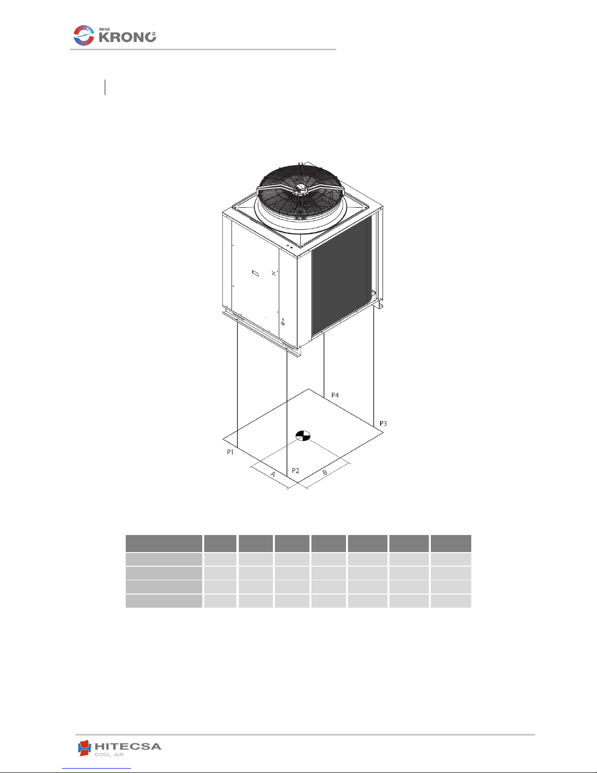
POMPE À
CHALEUR
1
2
3
4
A
B
TOTAL
801.1
62
52
50
60
569
598
224
1001.1
64
61
59
62
546
572
246
1201.1
68
68
62
62
525
567
260
1501.1
69
69
63
63
525
567
264
WEIGHT DISTRIBUTION (kg)
15
AIR COOLED WATER CHILLERS –AXIAL FANS
EKWXA/EKWXBA
11.15 207443 Rev104
• If is necessary to add or recuperate refrigerant 410A always do it in LIQUID phase. Supplying refrigerant
in gas or vapor form, by mistake, will result in wrong mixture conditions.
• Due to its high pressure and quick evaporation, refrigerant R410A cannot be kept in liquid phase inside
charge cylinder because bubbles would form, altering the readings.
• The electronic scale is reinforced with a four support-point structure for the weight sensor of the
refrigerant bottle.
• In addition, it can also be used for any type of refrigerant’s charge. The refrigerant’s charge is carried out
opening and closing the valve manually.
• Immediately repair all refrigerant leaks.
• Never overcharge the system.
• Never use compressor as vacuum pump.
• If during operation will appear symptoms of refrigerant loss is necessary to make leak test. Leak
detectors usually employed with CFC and HCFC cannot be used with R410a, due to chlorine in its
composition. A leak detector for R134A may be used but the sensibility will be lower (when sensibility is 1
for R134A, it falls to 0,6 for R410A).
• To find small leaks, you will need a detector for HCF. Sensibility for R410A is approximately 23 grams
per year.
• If gas leak is detected is necessary to remove and recuperate complete refrigerant charge. Pressurize
system with dry nitrogen. If leakage has been not detected break a vacuum, dehydrate and charge with
refrigerant.
Compressors with R410A refrigerant use polyester synthetic oil. Each compressor’s manufacturer
recommends a specific type of oil for its products. The compressor or the system should not be left opened
to atmosphere more than 15 minutes. Synthetic lubricants are used as ester (POE, Polyol Ester) that have
a high solubility with R410A. Since these types of oils are very hygroscopic, more care should be taken
rather than with the conventional ones. Furthermore, when these synthetic oils are mixed with minerals or
alkylbenzene, they deteriorate producing capillary obstruction or failures in the compressor. Do not mix
them under any circumstance.
COMPRESSOR LUBRICANT
REFRIGERANT CHARGE
Never use oxygen to pressurize system or purge lines for leak test. Oxygen reacts
violently with oil, which can cause an explosion resulting in damage, personal injury
or death.
If it is necessary to make brazing operation, first fill the circuit with dry nitrogen.
Burning refrigerant 410A results in toxic gas emissions.
ATTENTION!
ATTENTION!
16
AIR COOLED WATER CHILLERS –AXIAL FANS
EKWXA/EKWXBA
11.15 207443 Rev104
START UP
• Start up to be performed by qualified technical people.
• Make start-up check list and use similar check up for service and maintenance. Record chilled water inlet
and outlet temperatures and pressures, outdoor air temperature, volts and amps of each compressor and
fan motor, suction and discharge pressure of each compressor.
• Should remind that after four hours of system operation is necessary to clean air filters.
• Observe at least 3 cooling cycle operations.
• Due to the fact that the unit has frequency converters for compressors and fans, it’s essential that the
supply be at a minimum of 300 mA to prevent supply cuts caused by the differential switch.
LCX CONTROL
► START UP:
► SHUTDOWN:
•Check if all wires are well tightened.
•Check if all panels are firmly secured with screws.
•Verify if there is no refrigerant or oil leakage.
•Verify if unit is installed on level.
•Verify if there is enough space for service and maintenance.
• Check if drain holes in unit base are not blocked.
• Check if the cranckcase heater of each compressor has been energized at least 24 hours before unit start up.
• Check if air filters are clean and correctly mounted.
• Check all grills, air diffusers, air ducts and flexible connections.
• Be sure that electrical power source agrees with unit nameplate rating.
•Fans rotate in the right direction.
BEFORE START –UP

17
AIR COOLED WATER CHILLERS –AXIAL FANS
EKWXA/EKWXBA
11.15 207443 Rev104
MCX CONTROL (OPTIONAL UPGRADE)
► START MENU
Keypad utility
(UP) By pressing and holding this key for, at least, 3 seconds the unit will start up if it
was shutdown or it shuts down if it is running.
(DOWN) By pressing and holding this key, at least, 3 seconds the unit will toggle
between cooling and heating mode. If the unit is running, it needs to stop prior to
switching modes and then it must be started up once again.
(ESC) Pressing this key leads to a shortcut to the ALARMS menu.
(RETURN) This key takes the user to the MAIN MENU screen if it is pressed in the
START MENU screen. It is also used to enter menus for other selected options.
►MAIN MENU
Keypad utility
(UP) Used to scroll UP between highlighted
options.
(DOWN) Used to scroll DOWN between
highlighted options.
(ESC) Returns to the previous screen of a
highlighted option.
(RETURN) Advances to the next screen or sublevel of a highlighted option.
ON. Starts up the unit using the last settings.
OFF. Shuts off the unit according to the established time parameters.
Heat/Cool.
Toggles between operating modes.
18
AIR COOLED WATER CHILLERS –AXIAL FANS
EKWXA/EKWXBA
11.15 207443 Rev104
►PASSWORD LEVEL
There are 3 clearance levels for different parameters or system setting options.
Level L0: User Access, no password required.
Level L1: User-Maintenance Access.
Level L2: Manufacturer authorized Access ONLY.
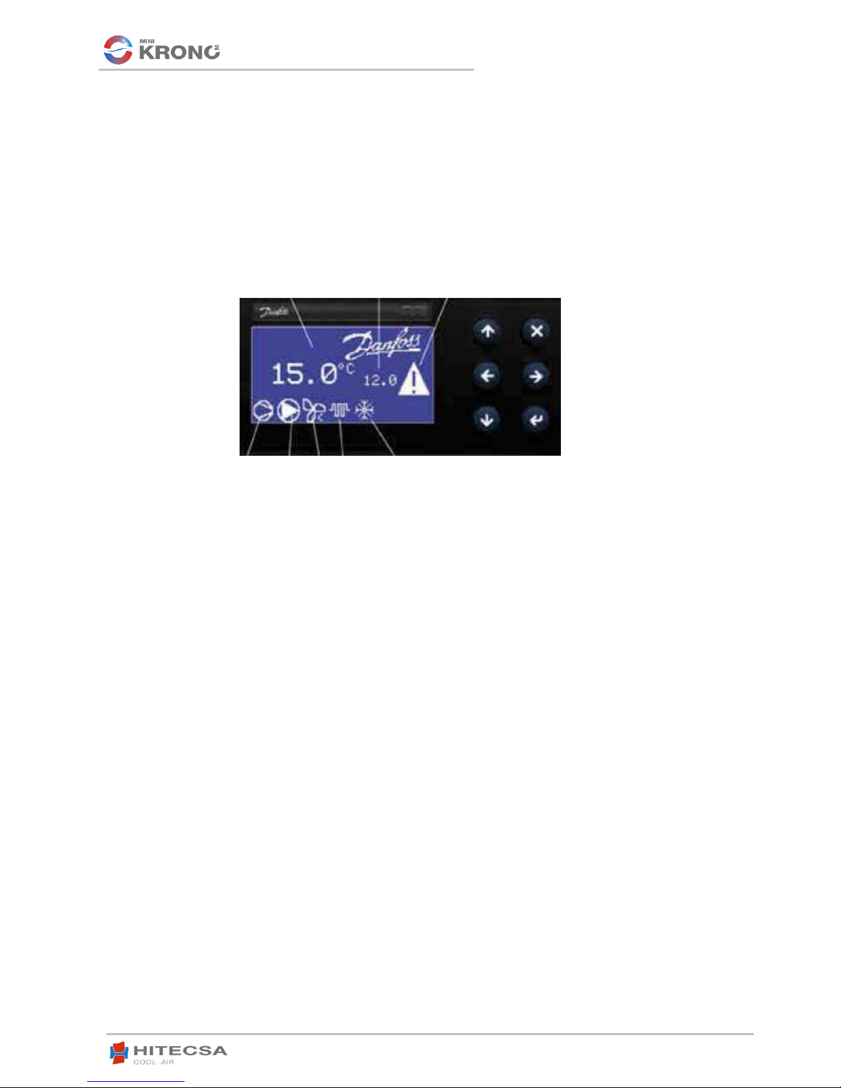
DISPLAY “A” DISPLAY “B” ALARMAS/NOTIFICATIONS
COMPRESSOR
WATER PUMP
EXTERNAL FAN
ANTI-FREEZE HEATER
COOL / HEAT / ANTI-FROST MODE

19
AIR COOLED WATER CHILLERS –AXIAL FANS
EKWXA/EKWXBA
11.15 207443 Rev104
►INPUTS / OUTPUTS
**The MCX controller automatically alternates
water pumps for the next start up cycle, after
24 service hours have been logged, in order
to prolong the life of the components. (Only
available for units with more than 1 water
pump)
POSITION
ANALOG INPUTS
DIGITAL INPUTS
ANALOG OUTPUTS
DIGITAL OUTPUTS
1
Intake water
temperature.
Differential pressostat / Flow
switch.
NO OUTPUTS. ONLY
when Condensation
Control OPTIONAL Kit
is installed, there is a
reading in ANALOG
OUTPUT slot #3.
Compressor 1
2
Outlet water
temperature.
Thermal protection
Compressor 1.
Compressor 2. (for
units with 2
compressors)
3
Cond / Evap
pressure Cool /
Heat.
Thermal protection
Compressor 2. (for units with
2 Compressors)
4 way valve (ONLY
available with Heat
Pump units)
4
Evap / Cond
pressure Cool /
Heat.
External fan termal sensors.
Anti-freeze heater
5
---
Safety pressostat. High
Pressure readings.
Water pump for 1-
pump KIT. (No Kit,
shows no output. If 2-
pump Kit is installed,
outputs are shown in
#9 and #10 slots.)
6
---
Remote Start-Stop.
External fans ALL set
to lowest speed
setting.
7
---
Remote Cool/Heat selection.
ONE fan in high
speed, the rest in the
lowest.
8
---
Second SETPOINT.
ALL fans in the high
speed setting
9
---
Thermal protection for Water
pump 1 (for 2-pump Kit).
---
10
---
Thermal protection for Water
pump 2 (for 2-pump Kit).
---
ANALOG INPUTS
DIGITAL INPUTS
0= Not Active
1= Active
ANALOG
OUTPUTS
DIGITAL OUTPUTS
0= OFF
1=ON
20
AIR COOLED WATER CHILLERS –AXIAL FANS
EKWXA/EKWXBA
11.15 207443 Rev104
►SYSTEM PARAMETERS
Display screen
Display screen “A”.
Select the Reading to be shown in Display
screen A when the unit is running. By default,
the reading shown on Display screen A when
the unit is shut down is “OFF”.
Display screen “B”.
Select the Reading to be shown in Display
screen B when the unit is running.
. Password
Displays Installer-Maintenance password.
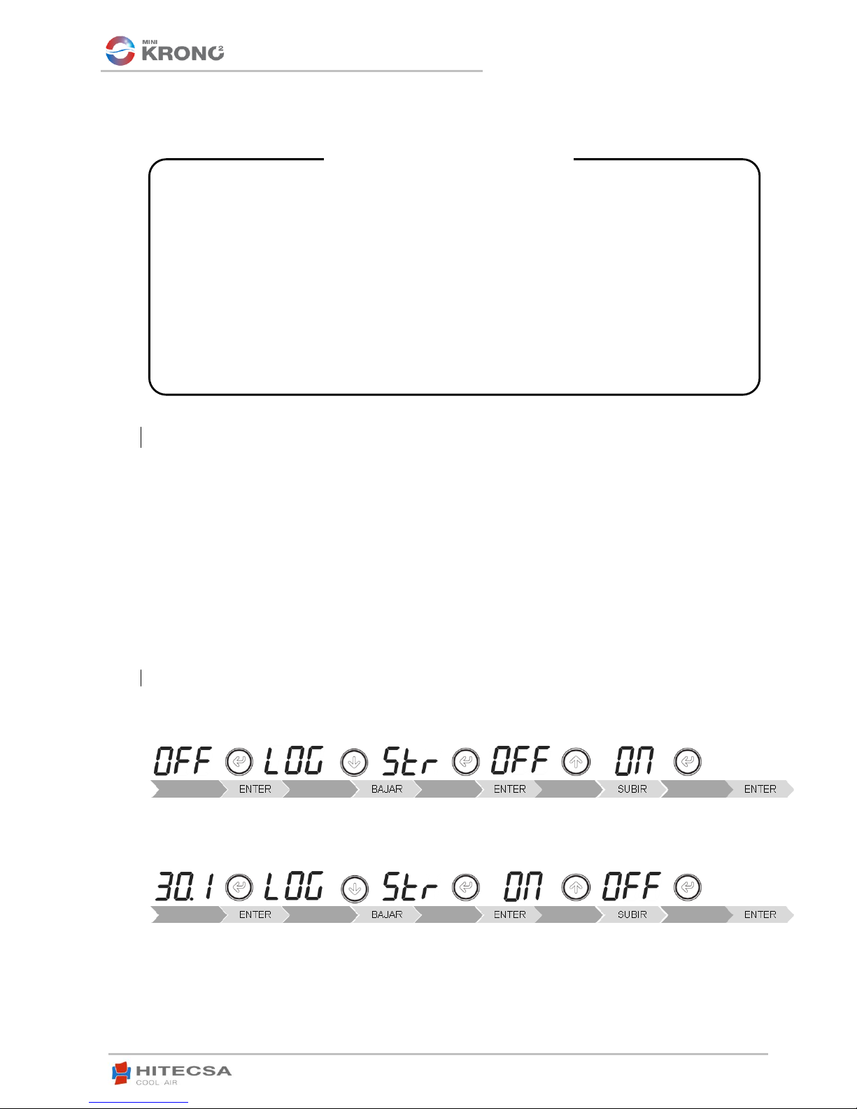
Setup
System ON/OFF.
Indicates wether the unit is running (ON) or if it is
shutdown (OFF), it also allows starting up or
shutting down the unit by selecting ON/OFF.
Restart After Disconnection Mode.
Following a sudden power outage, this indicates
the operational mode for restart.
System HEAT/COOL
Indicates current operating mode HEAT/COOL
and, it also allows switching between modes.
If the unit is running, it stops before switching
operating modes and then it is started up in the
new mode.
Scheduler Enable.
Enables/Disables Programming Mode.
►REGULATION PARAMETERS
Configuration
Temperature Regulation Entry
This is used to tell the system whether regulation
will be applied to IN or OUT water temperature.
Calibration of the Regulation Probes.
Adjusts probe regulation values in the range
between -99,9 and 99,9.
Setpoint.
Cooling Setpoint Temperature.
Sets the value of the operating Cooling Setpoint
temperature in ºC, by default this value is set to
7ºC. Values can range between 6,0 and up to
17,0ºC.
Lower Limit Setpoint Temperature.
This is used to set the lowest limit of the Setpoint
temperature in Cooling more.
By default this value is 6,0ºC.
High Limit Setpoint Temperature.
This is used to set the highest limit of the
Setpoint temperature in Cooling more.
By default this value is 17,0ºC.
Heating Setpoint Temperature.
Sets the value of the operating Cooling Setpoint
temperature in ºC, by default this value is set to
45ºC. Values can range between 35,0 and up to
55,0ºC.
Lower Limit Setpoint Temperature.
This is used to set the lowest limit of the Setpoint
temperature in Heating more.
By default this value is 35,0ºC.
High Limit Setpoint Temperature.
This is used to set the highest limit of the
Setpoint temperature in Heating more.
By default this value is 55,0ºC.
►COMPRESSORS
Activation
Activation of Compressor 1.
Activates or disables compressor 1.
AI1: Regulation of INTAKE water.
AI2: Regulation of OUTLET water.
OFF: No reading shown.
IdOF: ON/OFF state.
Set: Setpoint value for current operating mode.
reg: (Varies according to the model of the unit)
AI1: Intake water temperature. (Default setting)
AI2: Outlet water temperature.
OFF: No reading shown.
IdOF: ON/OFF state.
Set: Setpoint value for current operating mode. (Default
setting)
reg: (Varies according to the model of the unit)
AI1: Intake water temperature.
AI2: Outlet water temperature
OFF: The unit is set to Standby or OFF mode.
ON: The unit starts up.
EQUA: The unit resumes operation under the same settings
as the last time it was running before loss of power.
This manual suits for next models
1
Table of contents
Other Hitecsa Chiller manuals


Popular Chiller manuals by other brands


Daikin
Daikin EWAQ005AAV3P Operation manual

Carrier
Carrier PERFORMANCE 50VT-A24 installation instructions

Telemark
Telemark Cryogenics instruction manual

KoolMore
KoolMore OF-700 Instructions for use

Lennox
Lennox ECOLOGIC Series Installation, operation & maintenance manual

Skope
Skope Pegasus PG100HC-2 user manual


