Hitecsa ETN-24 SUPER-SI Series User manual

ETN-24 SUPER-SI SERIES
USER’S MANUAL
05.15 207403 Rev104

2
04.15 207403 Rev104
CONTENIDO
INSTALLATION INSTRUCTIONS................................................................................................................................3
WIRING CONNECTIONS ............................................................................................................................................3
MICRO SWITCH DIP ADJUSTMENTS........................................................................................................................4
OPERATION INSTRUCTIONS ....................................................................................................................................5
SWITCH ON / SWITCH OFF ......................................................................................................................................................5
TEMPERATURE ADJUSTMENT ................................................................................................................................................5
OPERATING MODES.................................................................................................................................................................5
TEMPERATURE LIMITS AND OFFSET .....................................................................................................................................5
FAN / AUTOFAN VENTILATION.................................................................................................................................................6
LOCKING / UNLOCKING THE THERMOSTAT’S BUTTONS......................................................................................................6
POWER SUPPLY .......................................................................................................................................................................6

3
04.15 207403 Rev104
INSTALLATION INSTRUCTIONS
Separate the terminal front panel from the back panel by pressing the blockage tab located at the
top of the thermostat case.
Remove the back panel.
In order to fasten the back panel to the wall, align it on the wall.
Install 3 fixing screws through the mounting holes.
Realize electrical connections as shown in electrical wiring diagram.
(see WIRING CONNECTIONS section).
In order to place the front cover, fit together the two bottom tabs on the bottom slots, and then
press to align the upper blockage tab in the upper slot.
Push until it would be fixed on the wall.
WIRING CONNECTIONS
Y1 COMPRESSOR 1
G FAN
Y2 COMPRESSOR 2
T EXTERNAL SENSOR
To
W2 ELECTRIC RESISTANCE – STEP 2
IN WINDOW CONTACT
INo
W1 ELECTRIC RESISTANCE – STEP 1
W3 ELECTRIC RESISTANCE – STEP 3
B/O
4 WAY VALVE CONNECTION
(B : heat pump power supply / O : cooling power supply)
C COMMON (power supply)
R LINE (power supply)
4
04.15 207403 Rev104
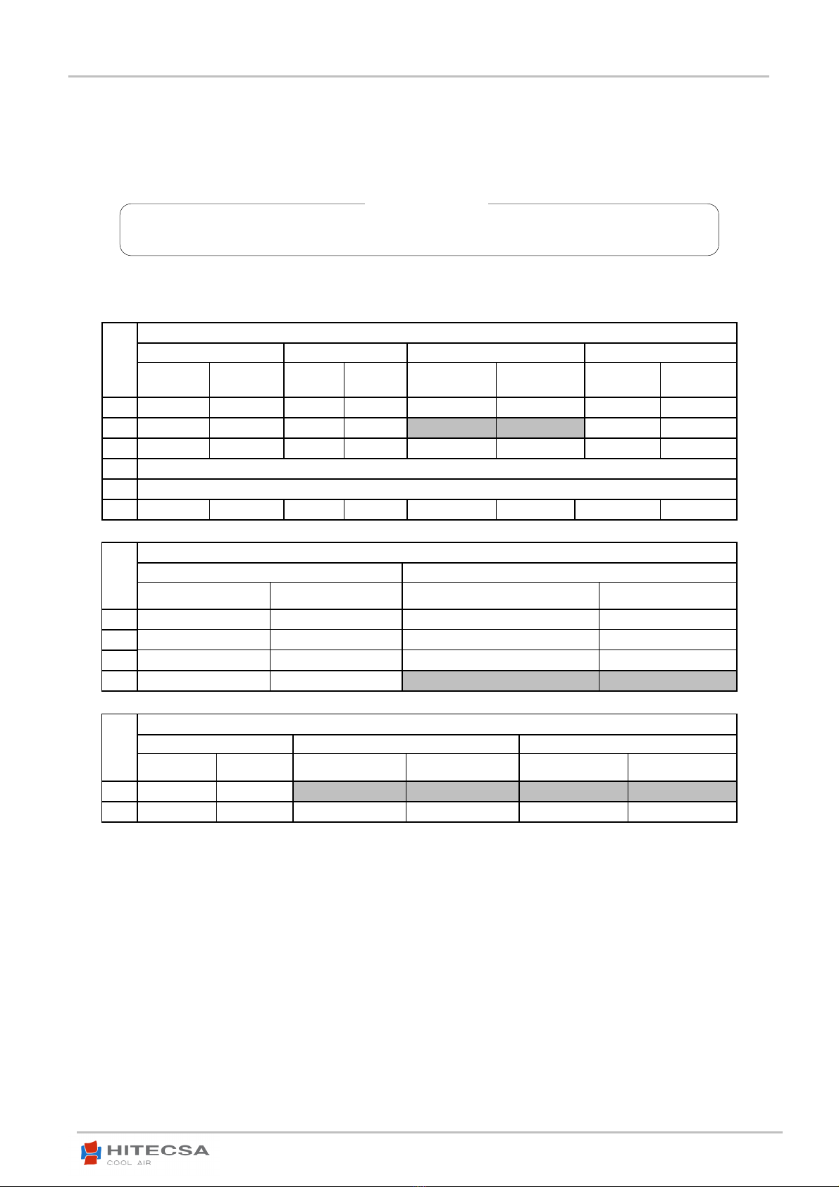
MICRO SWITCH DIP ADJUSTMENTS
SWITCH S1
Fan in economy mode Compressor time delay Modes Window contact
Fan auto Fan always on
4 min,
delay
Without
delay (test) Cooling only
Heating pump or
Cooling with
heating stage
System shut
down
Change to
economy
mode
S1.1 OFF ON
S1.2 OFF ON
S1.3 OFF ON
S1.4 UNUSED
S1.5 UNUSED
S1.6 OFF ON
SWITCH S2
Room temperature sensor Modes
Internal sensor (remote) External sensor Cooling only or cooling with heating stage Heat pump (4WV)
S2.1 ON OFF
S2.2 OFF ON
S2.3 ON OFF
S2.4 OFF ON
SWITCH S2
On screen Cooling with heating stage configuration Heat pump (4WV) configuration
Room
temperature
Set point
temperature Electric resistance Combustible Activated in heating Activated in cooling
S2.5
OFF ON OFF ON
S2.6 ON OFF
MICRO SWITCH DIP ADJUSTMENTS ARE SET AT THE FACTORY
ATTENTION !

5
04.15 207403 Rev104
OPERATION INSTRUCTIONS
SWITCH ON / SWITCH OFF
−
Press (ON/OFF) button to switch ON or switch OFF the thermostat.
−
The words "ON" or "OFF" will be displayed on the screen.
TEMPERATURE ADJUSTMENT
−
Adjust the SET POINT temperature using the buttons (+) or (–).
OPERATING MODES
Press the (MODE) button one time. Use the (+) or (–) buttons to change between modes:
−
Cooling The screen will display “Cool” on the screen.
−
Heating The screen will display “Heat” on the screen.
−
Auto The screen will display both words “Cool” and “Heat” on the screen and the current active mode will be shown blinking.
−
Fan only The word “Fan” will be displayed on the screen.
Important: The Cooling / Heating automatic change option has to be deactivated by a technician.
TEMPERATURE LIMITS AND OFFSET
−
With the terminal powered but turned OFF (the word “OFF” will be shown on the screen), press and hold the (ON/OFF) button for 5
seconds. The number “50” will be displayed on the screen.
−
With the (+) button increase the “50” number up to ”55”.
Cooling limit adjustment
−
Press the (ON/OFF) button.
−
The word “Cool” will be displayed blinking.
−
Adjust the cooling limit temperature using the (+) or (–) buttons. Range between 10ºC/30ºC. By default 10ºC.
Heating limit adjustment
−
Press the (ON/OFF) button.
−
The word “Heat” will be displayed blinking.
−
Adjust the heating limit temperature using the (+) or (–) buttons. Range between 10ºC/30ºC. By default 30ºC.
OFFSET adjustment (room temperature reading calibration)
−
Press the (ON/OFF) button again.
−
The word “0 SET” and “ºC” will be displayed blinking.
−
Adjust the calibration using the (+) or (–) buttons. Range between –6ºC/+6ºC. By default 0ºC.
Important: The user will be able to change the SET POINT temperature regardless of the imposed temperature limitation, but the
thermostat will work within the limit.
OFF ON
Cooling Heating Auto Fan only
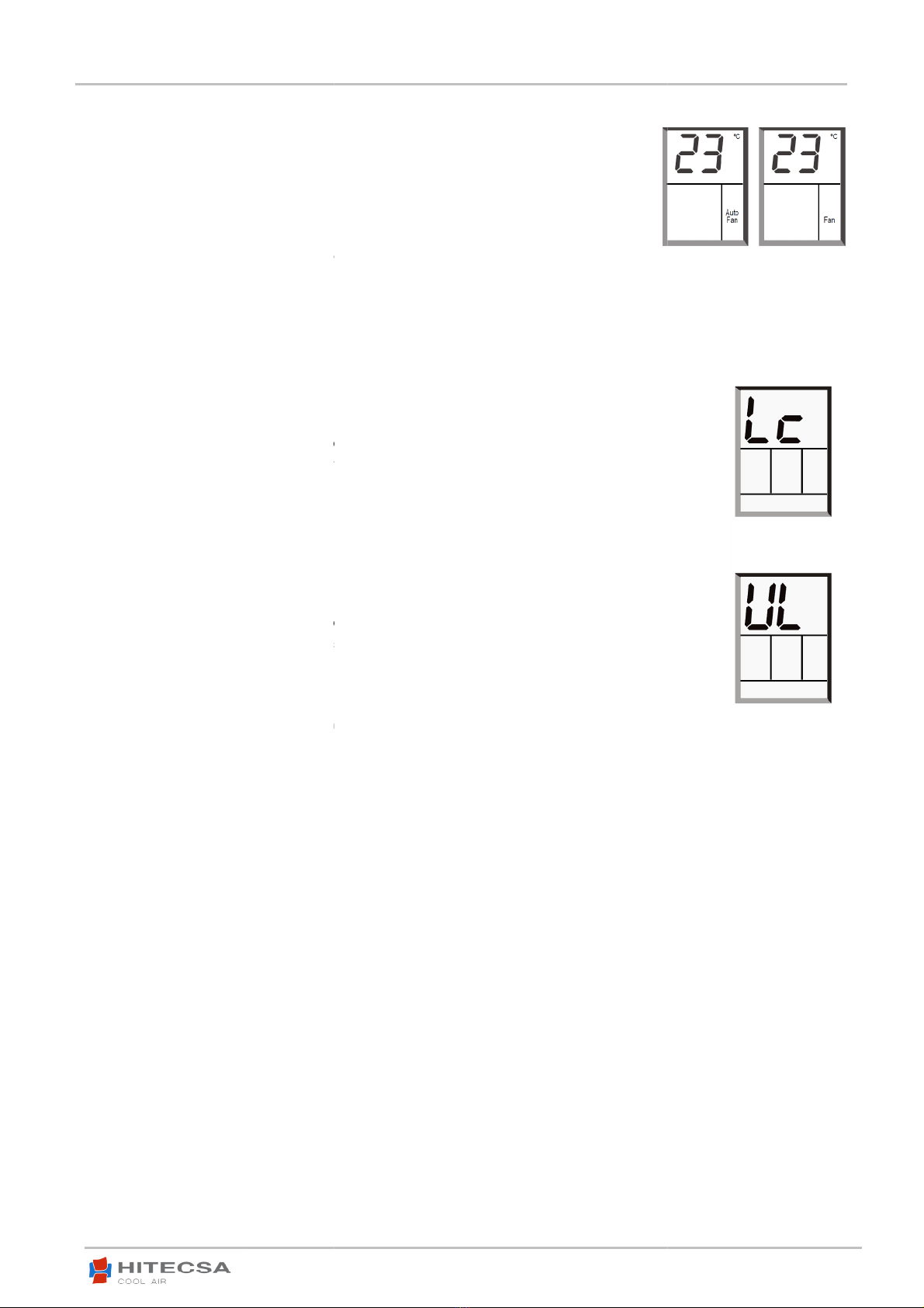
FAN / AUTOFAN VENTILATION
Press again the “FAN” button. Use the (+) or
−
Fan in auto mode
The screen will display
when there is a cooling or heating
demand
−
Fan in continuous mode
The screen will d
continuously.
Important: Fan in Auto mode
can’t be selected from “
LOCKING / UNLOCKING THE
THERMOSTAT’S
Locking the thermostat’s buttons
−
With the terminal powered but turned OFF (the word “OFF” will be shown on the screen), press and hold the
(ON/OFF) button for 5 seconds. The number “50” will be displayed on the screen.
−
With the (–
) button decrease the “50” number up to ”45”.
−
Press again the (ON/OFF) button. The word “UL” (unlocked)
−
Press the (+) button to lock the buttons of the terminal. The word “Lc” (locked) will be shown on the display.
−
Press
the (ON/OFF) button or wait 10 seconds to confirm and complete the locking process.
Unlocking the thermostat’s buttons
−
With the terminal powered but turned OFF (the word “OFF” will be shown on the screen), press and hold the
(ON/OFF) button for 5 seconds
. The number “50” will be displayed on the screen.
−
With the (–
) button decrease the “50” number up to ”45”.
−
Press again the (ON/OFF) button. The word “Lc” (locked) will be shown on the display.
−
Press the (–
) button to lock the buttons of the terminal. The
display.
−
Press the (ON/OFF) button or wait 10 seconds to confirm and complete the unlocking process.
Important
:
In the locking buttons mode
, remote control can
POWER SUPPLY
The
thermostat can operate at both 50Hz and 60Hz and voltage tolerances are ± 20%.
(–) buttons to select the automatic fan mode:
The screen will display
“Auto Fan” on the screen. The fan will operate only
demand
.
The screen will d
isplay “Fan” on the screen. Fan will operate
can’t be selected from “
Fan Only” mode.
THERMOSTAT’S
BUTTONS
With the terminal powered but turned OFF (the word “OFF” will be shown on the screen), press and hold the
(ON/OFF) button for 5 seconds. The number “50” will be displayed on the screen.
) button decrease the “50” number up to ”45”.
Press again the (ON/OFF) button. The word “UL” (unlocked)
will be shown on the display.
Press the (+) button to lock the buttons of the terminal. The word “Lc” (locked) will be shown on the display.
the (ON/OFF) button or wait 10 seconds to confirm and complete the locking process.
With the terminal powered but turned OFF (the word “OFF” will be shown on the screen), press and hold the
. The number “50” will be displayed on the screen.
) button decrease the “50” number up to ”45”.
Press again the (ON/OFF) button. The word “Lc” (locked) will be shown on the display.
) button to lock the buttons of the terminal. The
word “UL” (unlocked) will be shown on the
Press the (ON/OFF) button or wait 10 seconds to confirm and complete the unlocking process.
, remote control can
still be used to operate the unit.
thermostat can operate at both 50Hz and 60Hz and voltage tolerances are ± 20%.
6
04.15 207403 Rev104
With the terminal powered but turned OFF (the word “OFF” will be shown on the screen), press and hold the
Press the (+) button to lock the buttons of the terminal. The word “Lc” (locked) will be shown on the display.
With the terminal powered but turned OFF (the word “OFF” will be shown on the screen), press and hold the
word “UL” (unlocked) will be shown on the
Fan in auto
mode
Fan in
continuous
mode

HIPLUS AIRE
ACONDICIONADO S.L.
Masia Torrents, 2
Tel. +34 93 893 49 12
Fax. +34 93 893 96 15
08800 Vilanova i la Geltrú
Barcelona, Spain
www.hitecsa.com
The technical data and colou
rs of our prod
HIPLUS AIRE
ACONDICIONADO S.L.
Masia Torrents, 2
Tel. +34 93 893 49 12
Fax. +34 93 893 96 15
08800 Vilanova i la Geltrú
Barcelona, Spain
www.hitecsa.com
roducts are subject to change without prior notice.
Table of contents
Other Hitecsa Thermostat manuals


Popular Thermostat manuals by other brands


HomeMatic
HomeMatic HmIP-eTRV-C Mounting instruction and operating manual

Uponor
Uponor SetPoint 521 Installation and operation manual

Grasslin
Grasslin famoso 1000 rf user manual

Aube Technologies
Aube Technologies TI073-3W specification

Varifan
Varifan MST-1 user manual

White Rodgers
White Rodgers 1E78 installation instructions

DELTA DORE
DELTA DORE Tybox 117+ Installation and user guide

Ascon tecnologic
Ascon tecnologic PM343 user manual

Perry Electric
Perry Electric 1TX CR028WIFI Installation and use manual

Lennox
Lennox ComfortSense L3532H Operation manual

LK Systems
LK Systems Cq 1 Assembly instructions

Silvercrest
Silvercrest Classic Model L Operating instructions and safety advices