Hitecsa pGD1 User manual

USER MANUAL
USM_PGD1-MINIPGD_207897_180300_EN
pGD1 & Mini-pGD THERMOSTAT
THERMOSTATS FOR WATER-AIR & AIR-AIR UNITS
SOLO FRIO

Thank you for trusting the Hitecsa Products. Our company has been offering the market an extended range of specialized units for
air conditioning and cooling installations for over 35 years. Our approach is based on efficiency, adaptability, usability and practical
solutions. This has been the hallmark of our product catalogue.
The versatility of our factory allows us to contribute solutions, almost tailored to each project’s specifications, in search of a solution
to every problem that arises in design and implementation of air conditioning installations.
From all of us at Hiplus Aire Acondicionado, once again, thank you very much.

3
USM_PGD1-MINIPGD_207897_180300_EN
pGD1 & Mini-pGD
For AIR-AIR and WATER-AIR UNITS
INDEX
DESCRIPTION ..............................................................................................................4
OPERATION.................................................................................................................5
FRONT VIEW ..................................................................................................................... 5
HOW TO CHANGE THE TEMPERATURE SETPOINT ............................................................ 6
SYSTEM MODES................................................................................................................ 6
TIME SCHEDULE......................................................................................................... ….7
SUMMER/WINTER CHANGES ......................................................................................... 11
ON/OFF SETTING ............................................................................................................ 12
FAN MODE SETTING ....................................................................................................... 13
LOCAL NETWORK............................................................................................................ 14
DISPLAYED INFORMATION FOR THE MAIN UNIT ............................................................ 14
CONNECTION ................................................................................................................. 14
ALARMS .......................................................................................................................... 15
Alarm cancellation....................................................................................................... 15
Description of the alarm messages: pGD1 (HITSAA01) ............................................... 15
pGD1 & Mini-pGD THERMOSTAT

4
USM_PGD1-MINIPGD_207897_180300_EN
pGD1 & Mini-pGD
For AIR-AIR and WATER-AIR UNITS
DESCRIPTION
The pGD1 and the Mini-pGD are the new interfaces for the complete management of the units with pCO boards.
They comprise:
Motherboard with microprocessor for the execution of the control program, equipped with the necessary terminal to
connect the control components of the equipment: valves, compressors, fans, ...
The program is recorded in the EPROM and the entered parameters are stored in the EEPROM which secures that the
program is saved even when power is Off.
The motherboard also allows connection to a network of several motherboards called the pLAN network and also allows
the connection to a serial Supervision / Tele-assistance line via RS 485 protocol, CAREL communication protocol,
MODBUS protocol, LONWORKS protocol and even WEBGATE for remote management.
Terminal controlled by a microprocessor, with display and a keyboard from which the programming of the control
parameters and fundamental operations of the equipment are carried out.
The user terminal allows:
Initial machine configuration with password protected access.
The possibility to modify the fundamental parameters of the equipment with password protected access.
Modification at any time of set points, stop / start of the unit, change of summer / winter cycle and schedules in case
of incorporating a clock board, without needing a password.
Display of possible system alarms and acoustic warning.
The pGD1 and the Mini-pGD operations are very much alike, the displayed information is the same. The display size of
the Mini-pGD is smaller. Both have a backlight display.
The only differences are:
The size
The key symbols
The pGD1 has illuminated keys
The pGD1 can be mounted on a panel and allows wall installation while the Mini-pGD can only be mounted in panel.
Two types of software are available:
HIT005: standard software for all units for which the PGD1 is not an option i.e. the units equipped with Free
Cooling, return fans, heat recovery System, etc…
HITSAA01: This software is used for pGD1 when it is installed as an option without any accessory for air
treatment.
At first sight we observe that the HIT005 menus are numbered with figures (1, 2, 3,…) and the HITSAA01 are marked with
letters (A, B, C,…).

5
USM_PGD1-MINIPGD_207897_180300_EN
pGD1 & Mini-pGD
For AIR-AIR and WATER-AIR UNITS
OPERATION
FRONT VIEW
ALARM KEY: Press to display the alarms on the screen. The red illuminated key shows that there is an alarm. (only
PDG1 terminal)
.
PROGRAM KEY: Press to enter the general menu. The main menus are shown.
ESCAPE KEY: In any submenu it allows to go back one level. From the main menu it gives access to the Help
function.
UPWARD ARROW KEY: Move through menus or changing values of the control parameters.
ENTER KEY: Confirmation of the entered values.
DOWNWARD ARROW KEY: Move through menus or changing values of the control parameters.
PGD1 termninal
Mini PGD terminal

6
USM_PGD1-MINIPGD_207897_180300_EN
pGD1 & Mini-pGD
For AIR-AIR and WATER-AIR UNITS
OPERATION
HOW TO CHANGE THE TEMPERATURE SETPOINT
1. Press the key to display the previous screen.
2. Select the SETPOINT menu by pressing the key. The following screen will be displayed:
2. Press the key to enter the modification function of the temperature parameters.
3. Modify the parameters by pressing the or keys (up) (down) to set the desired temperature.
Confirm the entered values by pressing the key.
SYSTEM MODES
Control of the unit equipped with accessories (HIT005, pGD is a standard
feature):
From the “Main Menu” select the "WINTER/SUMMER” submenu. Change
the operation mode there.
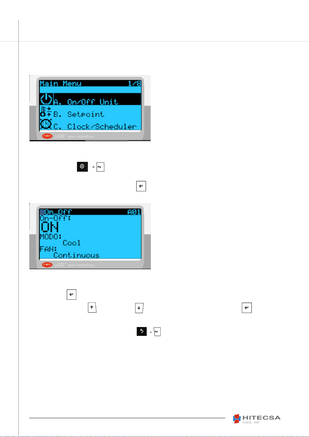
Control of the standard unit (HITSAA01, pGD is an option):
From the “Main Menu” select the “On/Off Unit” submenu and change the
operation mode there.

7
USM_PGD1-MINIPGD_207897_180300_EN
pGD1 & Mini-pGD
For AIR-AIR and WATER-AIR UNITS
OPERATION
TIME SCHEDULE
Important: Should the unit be equipped with a TH-TUNE terminal proceed to disconnect the TH-Tune prior to making any
modification on the pGD1.
The start-stop orders made from the keyboard will always prevail to any time schedule that may be activated.
Note: The PCO100CLK0 board (available as an option) is required to access these menus when other controllers than the µPC o PCO3
are used. The clock function shall be activated as well from the user menu (password 1996).
Clock setting in pGD1 when it is a standard feature (HIT005)
1. Press the “Prog” key
2. Select the menu 5. TIME SCHEDULE
3. Modify Hour, Date and Day
Time schedule setting when pGD1 when it is a standard feature (HIT005)
4 different start-up types are available. When the Time Schedule function is activated, the word “FASE” is shown on the screen:
A. Manual type: by selecting this type of start-up the unit will be ON or OFF without taking into account the internal clock.
Example:
The unit will remain stopped until the start-up type
is changed.
B. ON/OFF type: Week schedule. 3 differentsettings are available for each day of the week. For each of these settings you may choose
between up to 3 different time sections.
Select the “Schedule ON-OFF” start-up type from the menu 5.
Afterwards define the three settings:
Example: The programme nº1 will be activated from Monday to Thursday. The unit will start
working at 6:30 and will stop at 11:00. It will be working again from 11:30 to 13:30 and from
15:00 to 19:00. On Friday the programme nº3 will be activated and the unit will be working
from 7:00 to 15:00. On Saturday and Sunday no programme will be activated and the unit will
remain stopped.
8
USM_PGD1-MINIPGD_207897_180300_EN
pGD1 & Mini-pGD
For AIR-AIR and WATER-AIR UNITS
OPERATION
TIME SCHEDULE
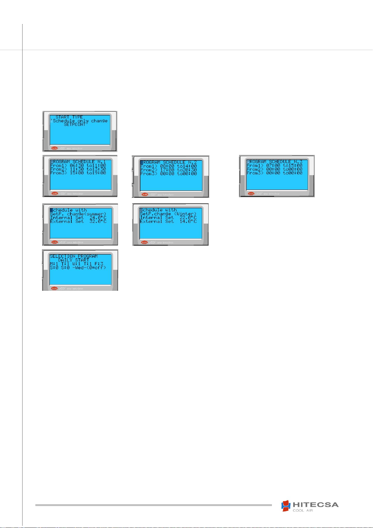
C. Schedule only change of Setpoint: Similar to the ON-OFF type but in this case the unit is not stopped. The setpoint change is
realized according to the time sections and the selected days. Remember that it will be possible to modify the working setpoint from the
“Clock” menu only instead of the “Setpoint” menu.
Select the “Schedule only change of Setpoint” start-up type from the menu “5”.
Afterwards define the three settings:
Define the setpoint temperatures between which
you will switch in each section of the schedule.
The internal Set. is the Setpoint that is within the
section and the external Set. is outside the section.
Example: The programme nº1 will be activated from Monday to Thursday. Internal Setpoint
from 6:30 to 11:00, etc.

9
USM_PGD1-MINIPGD_207897_180300_EN
pGD1 & Mini-pGD
For AIR-AIR and WATER-AIR UNITS
OPERATION
TIME SCHEDULE
D. ON-OFF schedule type with SET limit of ON: The Start/stop activation are made according to the “B” ON-OFF type and includes
a start-up safety feature outside the programmed time schedule when the temperature exceeds the limit setpoint temperature values
defined by the user.
By selecting this option the “Set” setpoint screen is disabled too and the modification shall be made with the “Clock” key.
Select the “Schedule ON-OFF with SET limit of ON” from the menu “5”.
Afterwards define the three settings:
Configure the setpoint temperatures and the
Internal Set and the limit where the unit will be
activated even though it is stopped (outside the
section).
Differential of temperature that you will apply to the setpoint in order to stop again the unit.
Example: The programme nº1 will be activated from Monday to Thursday. The unit will start
working at 6:30 and will stop at 11:00. It will be working again from 11:30 to 13:30 and from
15:00 to 19:00. The unit will start working again outside these hour sections in case when the
set limits are exceeded (Out of these hours the machine will start if the established limits are
exceeded (either whether the temperature is higher than the set limit in the Cooling mode or
lower in the Heating mode).
E. Forced: From the Start-up type screen press the ‘Prg’ key during a few seconds. To deactivate this function you must press the On-
Off key to stop the unit and press it again to leave the unit in the type of start-up that had been selected previously.
This option starts the machine during an established time in hours when you have selected the time schedule and for example you are
outside the schedule. When the forced time finishes the system returns to the type of start-up prior to the forced action.

10
USM_PGD1-MINIPGD_207897_180300_EN
pGD1 & Mini-pGD
For AIR-AIR and WATER-AIR UNITS
OPERATION
TIME SCHEDULE
Clock set when the pGD1 is an option (HITSAA01)
1. Press the Prog key
2. Select the C. Clock /Schedule menu
3. Modify Day, Date and hour
Enable or disable DST (Daylight Saving Time)
By default, commonly established for the EC: last Sunday of March adjust clock from 02:00 a.m. to 03:00 a.m. and the last Sunday of
October readjust clock from 03:00 a.m. to 02:00 a.m.
Example:
DST of 60 min. Enabled from the first Monday of
February at 10:00 (goes off at 11:00) until the last
Sunday of October at 3:00 goes back at 2:00.
The pGD1 is an option (HITSAA01)
Various types and possible setting options are available:
A. Setting for eachday of the week except public holiday.Two Setpoint values SET1 (cool) and SET2 (heat) that will be defined in the final
screen.
Example:
Start-up on Monday at 8:00 with setpoints SET1
and SET2 for Cool and Heat respectively until
14:00 and operation again from 15:00 until 20:00.
B. Schedule for up to 3 holiday periods.
Enter the date of start and end of period together
with the setpoints if it is ON or OFF.
Example:
Period from 25/12 to 31/12 in cold and heat
operation with SET1 and SET2 setpoints.
From 1/8 to 31/8 SET1 setpoint Cool only.
C. Schedule for single holiday days, up to 6 different days.
Enter the holiday day date and the setpoints, OFF
when it will be Off.
Example:
Day 1/05 in cold and heat operation with the same
SET1 setpoint.
D. Configuration of the two SET1 and SET2 setpoints
Enter the values for the two setpoints (SET1 and
SET2) that you have been using when setting the
programmation.
Example: SET1=20°C and SET2=22°C

11
USM_PGD1-MINIPGD_207897_180300_EN
pGD1 & Mini-pGD
For AIR-AIR and WATER-AIR UNITS
OPERATION
SUMMER/WINTER CHANGES
1. Press the key to display the previous screen.
2. Select the ON/OFF menu. When pressing the key the following screen appears:
3. Press the key to access the modification function to change the parameters of the mode.
4. By pressing the key (up) or the key (down) we select the desired mode. Press the key to confirm the entered
values.
12
USM_PGD1-MINIPGD_207897_180300_EN
pGD1 & Mini-pGD
For AIR-AIR and WATER-AIR UNITS
OPERATION
ON/OFF SETTING
1. Press the key to access the previous screen.
2. Select the ON/OFF menu.When pressing the key the following screen appears:
3. Press the key to access the modification function to change the operation mode.
4. By pressing the key (up) or the key (down) we select either ON or OFF. Press the key to confirm
the entered values.
5. Once the values have been modified press the key to go back to the previous menus.

13
USM_PGD1-MINIPGD_207897_180300_EN
pGD1 & Mini-pGD
For AIR-AIR and WATER-AIR UNITS
OPERATION
FAN MODE SETTING
1. Press the key to access the previous screen.
2. Select the ON/OFF menu. When pressing the key the following screen appears:
3. Press the key to access the modification function to change the operation mode.
4. By pressing the key (up) or the key (down) we select the desired mode. Press the key to confirm
the entered values.

14
USM_PGD1-MINIPGD_207897_180300_EN
pGD1 & Mini-pGD
For AIR-AIR and WATER-AIR UNITS
OPERATION
LOCAL NETWORK
When the control of several units is made from one terminal only we call it RED-LAN.
From the Main Menu select “Board Change”. A screen is displayed and it shows the actual unit stating “Unit” and the unit
we want to switch to “Pass to unit”. We change this value and press Enter to confirm.
DISPLAYED INFORMATION FOR THE MAIN UNIT
Unit: 01
Number of the unit to which the terminal is connected to.
12:00
Actual hour (only available if the clock board is installed. This feature is an option.)
/
Operation mode of the unit, cool and heat pump
Al
Shows if there is any active alarm.
20.0 ºC
Return temperature.
Unit Off
Unit status. Various information may be displayed: Unit Off; Time Schedule; Remote Unit Off.
CONNECTION
Connection to the medium sized or small µPC or to PCO3 with a 6 wires phone cable. Use TCONN for lines longer than 50 m (Shielded
twisted 4 wires cable. Refer to the diagram).
15
USM_PGD1-MINIPGD_207897_180300_EN
pGD1 & Mini-pGD
For AIR-AIR and WATER-AIR UNITS
ALARMS
All the alarms that will be displayed on the terminal except the alarms that are Warnings will make the unit stop.
Alarm cancellation
This button will be illuminated when the unit has an active alarm. By pressing that button we stop
the sound alarm. When pressing again that button we cancel the alarm if the problem has been solved.
In case when the problem should not be solved, please call for Technical Assistance.
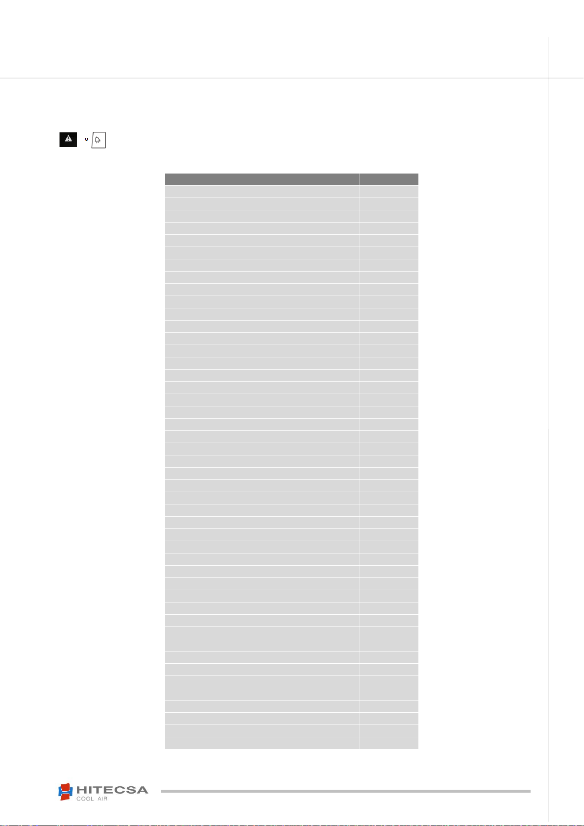
Description of the alarm messages: pGD1 (HITSAA01)
Message / Description
Type
Thermal Compressor 1
Alarm
Thermal Compressor 2
Alarm
Thermal fan C1 and/or High Pressure C1
Alarm
Thermal fan C2 and/or High Pressure C2
Alarm
Exceeded Set High Room Air Temp.
Alarm
Exceeded Set Low Room Air Temp.
Alarm
Low Pressure 1 and/or Min. Pressure Switch
Alarm
Low Pressure 2 and/or Min. Pressure Switch
Alarm
Pressure Switch Low Pressure 1
Alarm
Pressure Switch Low Pressure 2
Alarm
MaintenanceComp.1-C1 (Indication only)
Warning
MaintenanceComp.1-C2 (Indication only)
Warning
MaintenanceComp.2-C1 (Indication only)
Warning
MaintenanceComp.2-C2 (Indication only)
Warning
Mainten. Comp. Recov.(Indication only)
Warning
Serious Alarm Thermostats Security Interlock
Alarm
Defrost probe 1 Default
Alarm
Defrost probe 2 Default
Alarm
Dirty filter (Indication only)
Warning
Thermal Resistances 1 and 2
Alarm
Thermal Resistance
Alarm
General AL. burner
Alarm
Serious Memory Default (Indication)
Warning
Missing clock or not working
Alarm
Maintenance Unit (Indication only)
Warning
Serious Alarm Probe Broken or disconnected Return Temp.
Alarm
S.pLAN T/HR without connec. (Check Red pLAN)
Alarm
Alarm Probe Broken or disconnected Outdoor Temper.
Alarm
Alarm Probe Broken or disconnected Return Humidity
Alarm
Alarm Probe Broken or disconnected Outdoor Humidity
Alarm
Alarm Probe Broken or disconnected Temper. Air Supply
Alarm
Alarm Serious Summer Setpoint Lower than Winter Stpt
Alarm
SERIOUS ALARM Low Pres. 1 and/or P.min
Alarm
ALARM SERIOUS Low Pres. 2 and/or P.min
Alarm
Maintenance Indoor Fan (Indication only)
Alarm
CounterPERM. Comp.1-C1 (end, install again)
Alarm
CounterPERM. Comp.1-C2 (end, install again)
Alarm
CounterPERM. Comp.2-C1 (end, install again)
Alarm
CounterPERM. Comp.2-C2 (end, install again)
Alarm
Counter PERM. Unit (end, install again)
Alarm
Counter PER.Indoor Fan (end, install again)
Alarm
Alarm High P. + Low Comp. recovery
Alarm
Thermal Compressor recovery
Alarm
SERIOUS Thermal Fan C1 and/or High Pressure C1
Alarm
SERIOUS Thermal Fan C2 and/or High Pressure C2
Alarm
Serious Alarm High Pr.+Low Comp. recovery
Alarm

16
USM_PGD1-MINIPGD_207897_180300_EN
pGD1 & Mini-pGD
For AIR-AIR and WATER-AIR UNITS
We reserve the right to add modifications without prior notice.
Other manuals for pGD1
1
This manual suits for next models
1
Table of contents
Other Hitecsa Thermostat manuals


Popular Thermostat manuals by other brands

Watts Industries
Watts Industries Thermostat user guide

Dettson
Dettson R02P032 Installation instructions and homeowner's manual

Drayton
Drayton Lifestyle LP111Si User instructions

Tekmar
Tekmar tekmarNet 552 Installation & operation manual

Fidure
Fidure A2132FAC user guide

ComfortNET
ComfortNET Touchscreen Thermostat System Homeowner user guide

Webee
Webee Smart Thermostat Getting started

ApenGroup
ApenGroup SMART WEB Series Operating, Installation and Programming Manual

Heltun
Heltun HE-ZW-THERM-FL1 user manual

TemperZone
TemperZone SAT-1 User operating instructions

C.O.K.
C.O.K. RDF 642 2-00 Series manual

Honeywell
Honeywell T8095A/191108AJ owner's manual


