Hitecsa TH-TUNE User manual
USER MANUAL
USM_TH-TUNE Aire-Aire y Agua-Aire_207960_181005_EN
TH-TUNE
PACKAGED AIR-AIR AND WATER-AIR UNITS
SOLO FRIO

Thank you for trusting the Hitecsa Products. Our company has beenoffering the market an extended range of specialized equipment
for air conditioning and cooling installations for over 35 years. Our approach is based on efficiency, flexibility and on practical
solutions. This has been the hallmark of our product catalogue.
The versatility of our factory allows us to deliver solutions that can meet any requirement and we endeavour solving any problem
that may arise in designing and implementing air conditioning installations.
From all of us at Hiplus Aire Acondicionado, once again, thank you very much.

3
USM_TH-TUNE Aire-Aire y Agua-Aire_207960_181005_EN
TH-TUNE
Packaged Air-Air and Water-Air units
TH-TUNE Air-Air / Water-Air
INDEX
INSTALLATION INSTRUCTIONS ......................................................................................... 4
ELECTRICAL CONNECTIONS .............................................................................................. 5
POWER SUPPLY.................................................................................................................5
CONNECTIONS ..................................................................................................................5
OPERATION MANUAL ...................................................................................................... 6
DISPLAY.............................................................................................................................6
ON-OFF CONTROL.............................................................................................................6
TEMPERATURE ADJUSTMENT...........................................................................................6
Th-tune internal temperature probe calibration 6
SYSTEM MODES ................................................................................................................6
INDOOR FAN MODES .............................................................................................................6
TIME SCHEDULING .................................................................................................................7
Examples of time programming 7
WARNING AND INFORMATION SIGNALS......................................................................................8
Description of the Warning Codes 8
ALARMS...............................................................................................................................8
Alarm Codes Reset 8
Alarm Codes Description 9
DESCRIPTION OF THE MODBUS PARAMETERS ............................................................... 10
ADDRESS PARAMETER CONFIGURATION........................................................................10
BAUD (RATE) PARAMETER CONFIGURATION..................................................................10
4
USM_TH-TUNE Aire-Aire y Agua-Aire_207960_181005_EN
TH-TUNE
Packaged Air-Air and Water-Air units
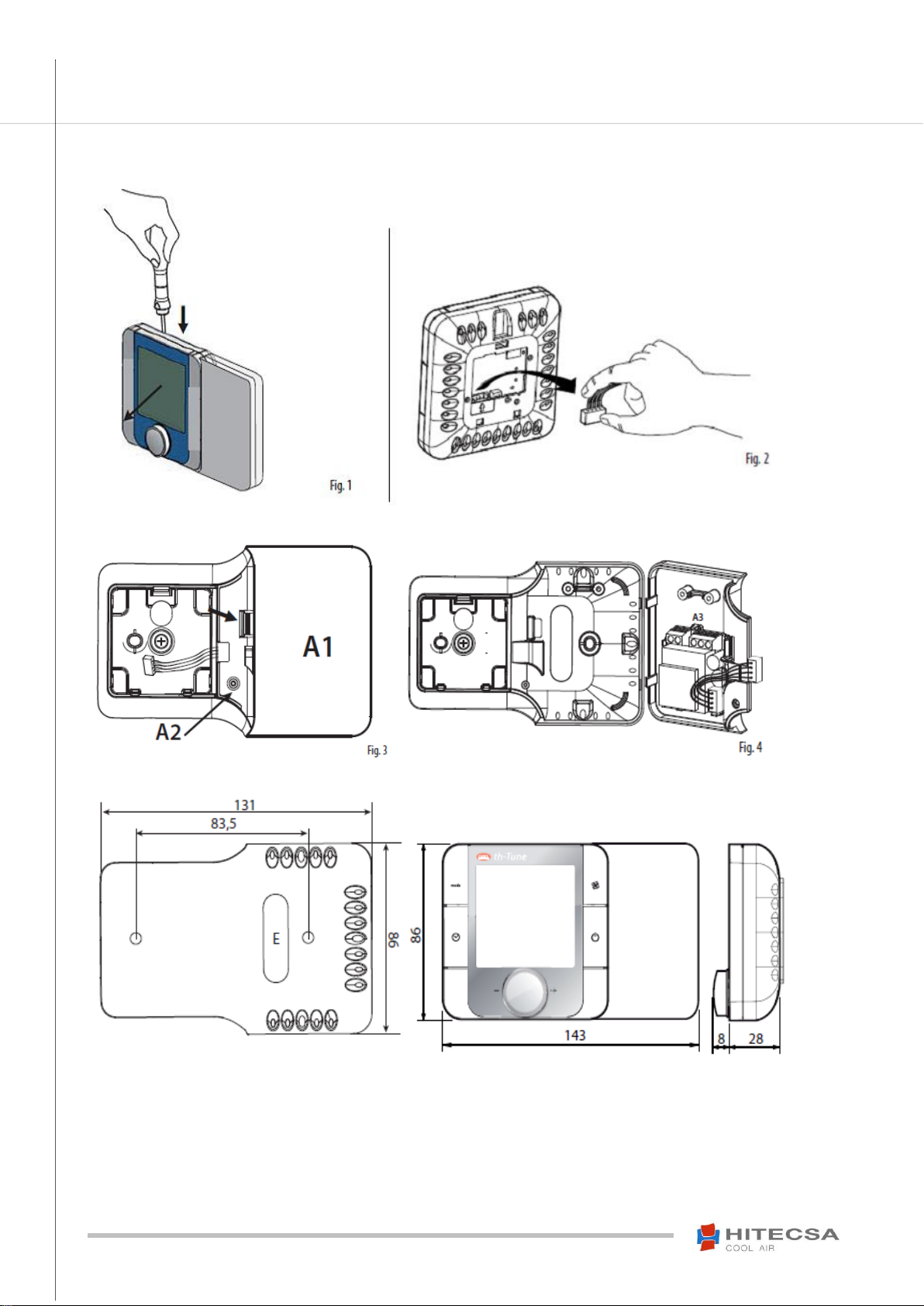
INSTALLATION INSTRUCTIONS
5
USM_TH-TUNE Aire-Aire y Agua-Aire_207960_181005_EN
TH-TUNE
Packaged Air-Air and Water-Air units
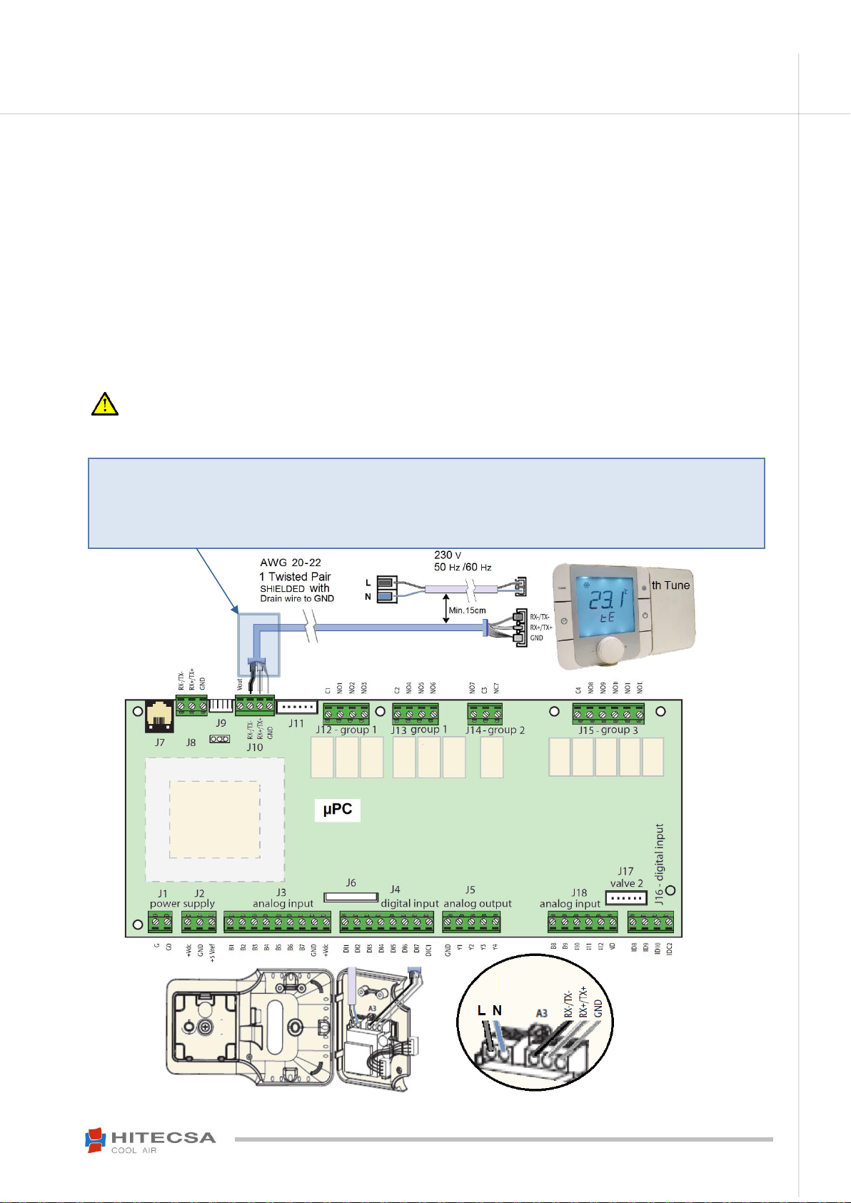
ELECTRICAL CONNECTIONS
POWER SUPPLY
The thermostat can operate at 50 Hz/60 Hz, and the voltage tolerances are 230V ± 20%.
CONNECTIONS
Two wire power supply AWG18 cable (Cable section: 05 mm² to 1.5 mm²) connected to 230 VAC (L+N) terminals.
Shielded and twisted pair AWG 20/22 communication cable with drain wire connected to GND. Connect to the
terminals of the board and the thermostat. Maximum length = 500 m.
If the “Cn” message does not disappear from the TH-Tune display, it means that communication between the
thermostat and the control board has failed (possible reasons: wrong connection to the terminals, the “Rx/Tx+” and
the “Rx/Tx-“cables have been swapped; the connection has been made through the wrong connector; etc…).
Proceed to verifying the cable connection and make sure that they are connected to the right terminals.
ATTENTION –To avoid possible electromagnetic interferences, separate the power cable from the
communication cable as much as possible. Never insert them in the same cable conduits including the conduits of
the electrical boxes.
Depending on the unit model, connection can be made to the terminal block instead of directly to the board.
Please refer to the wiring diagrams.
For example: Units equipped with an air flow controller: Connection of the air flow controller to the
thermostat is interspersed with the board. The function of the terminals is to prevent wrong
connections.
6
USM_TH-TUNE Aire-Aire y Agua-Aire_207960_181005_EN
TH-TUNE
Packaged Air-Air and Water-Air units
OPERATION MANUAL
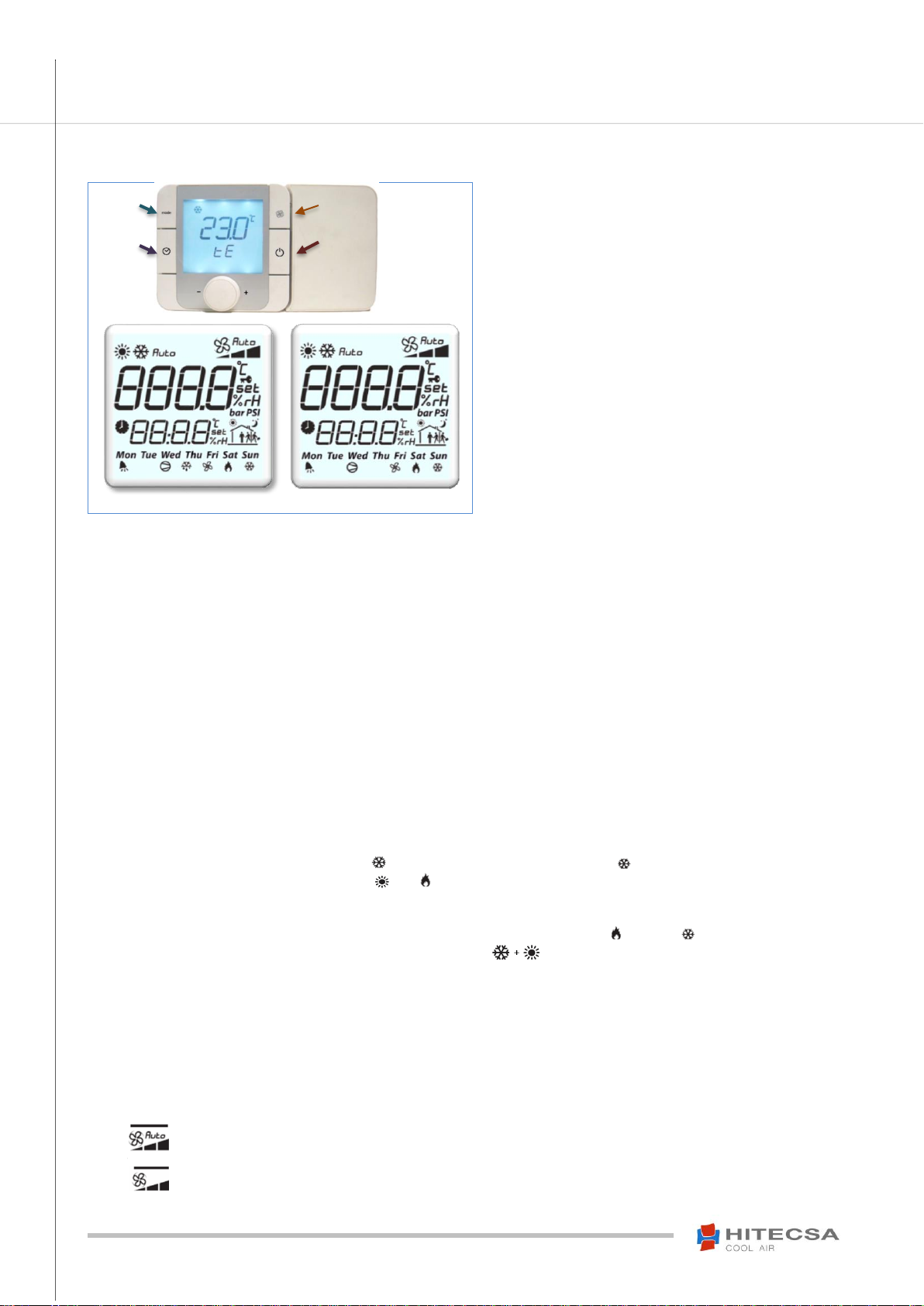
DISPLAY
- Backlighted LCD display.
- Two alphanumerical 4-character strings.
- Set of symbols to obtain the entire information
of the operation simultaneously on the same
screen.
- Multi-function centre button: rotate to scroll
through the menus or to increase/decrease a
value and press to enter or to select.
ON-OFF CONTROL
Press and hold the button (On / Off) for two seconds to turn the thermostat on or off. The word "OFF" will be displayed on the thermostat
screen when it is in the Off position.
NOTE: The thermostat will show "OFFd" if the remote on-off contact is open and "OFFs" when communication Off is ordered through
Modbus. When switching on for the first time or after a power failure the message “Cn” will be displayed during a few seconds until
communication with the board is established.
TEMPERATURE ADJUSTMENT
Adjust the setpoint temperature by turning the central button.
Th-Tune internal temperature probe calibration
Use a positive or negative correction value that will be added to the probe value. The zero value will not change the probe value.
Press and hold the FAN + ON/OFF keys until a password is required.
Access to the configuration menu with the “22” password and press to validate. Rotate the central button until the
PCAL option appears and select it.
Be careful when changing any other parameter from this menu! That might disable the Th-TUNE.
Turn the central button to modify the correction value and press to validate.
SYSTEM MODES
Press the (Mode) button to scroll through the available operation modes.
Available system modes:
Cooling Mode –The display will show the icon and at the lower right corner the icon.
Heating Mode –The display will show the and icons. This mode is not available for cooling only machines.
Automatic Mode –The display will show: “Auto”. This mode is not available for cooling only machines. This
operating mode will change between cold and heat depending on the selected temperature setpoint. The mode that
is active at each moment will be indicated in the lower right corner of the display: Heating, Cooling.
Only Fan –The display will show two icons at the same time: . The fan will operate in a continuous mode and
will not take into account the temperature value setpoint. Only one speed is available.
NOTE: When the outdoor temperature is very low and you want the machine to operate in the cooling mode, either
by selecting this mode or by selecting the Auto mode. If the machine is NOT equipped with the condensation control
option it could stop due to the activation of an alarm.
Be careful with keeping the Auto mode activated continuously! The conditions that lead to the previous error could
be given.
Indoor Fan Modes
“Fan / Autofan” with Ventilation “Continuous / Auto”
Press the (Fan) button to alternate between the automatic and the continuous ventilation mode.
With automatic fan - The icon on the screen will show "Auto".
The fan only works when there is a request for cold or heat.
Without the automatic fan - The word "Auto" disappears from the icon.
The fan operates in the continuous mode.
Clock
Mode
Fan
On /Off
2 Water_Air
1 Air_Air

7
USM_TH-TUNE Aire-Aire y Agua-Aire_207960_181005_EN
TH-TUNE
Packaged Air-Air and Water-Air units
OPERATION
Time scheduling
Examples of time programming
oContinuous Day Schedule from 9:00am to 9:00pm
- t1: Start up, “8:45”
- t2, t3: Unscheduled, “--:--“
- t4: Stop, “20:00”
- t5, t6: Unscheduled, “--:--“
oSplit Day Schedule 9:00-13:00 and 16:00-20:00
- t1: Start up, “8:45”
- t2: Stop for midday break or reduce to a more economicalsetpoint.“13:00”
- t3: Start up or return to normal setpoint. “16:00”
- t4: Stop, end of the day “20:00”
- t5, t6: Unscheduled, “--:--“
oDomestic Schedule
- t1: Start up, “7:00”
- t2: Stop for absence or reduce to a more economicalsetpoint. “8:30”
- t3: Start up or return to normal setpoint. “13:15”.
- t4: Stop for absence or reduce to a more economical setpoint. “15:30”
- t5: Start up or return to main setpoint
- t6: Night stop or reduce to a more economicalsetpoint. “13:00”
Keep the button “ ” pressed for at least 3 seconds until “Clock” appears (if the
stated hour is not correct you can change it here): turn the central button and
chose “Time band” or select “Esc” for escape.
- In general, so as to scroll through the different screens, turn the central button and
select by pressing it.
Turn the central button to select the desired type of program.
- Daily schedule by selecting every day, weekly schedule (shows all days), or one
schedule from Monday to Friday and another from Saturday to Sunday, press the
central button to select the wished day or days.
By turning the button you can select 6 different screens that correspond to 6
different times throughout the day (refer to the screens).
- On each screen a setpoint temperature is programmed if we want the equipment
to be running or "OFF" if we want to stop it and the time at which it will be
activated. If instead of an hour we select “--:--“, the screen will be deprogrammed
and it will not be activated.
- The time that we can select in each screen will always be greater than the time of
the previous screen.
- The operation mode can not be modified, it will be the one that is active.
- To leave, select the ESC screen.
- The screen figures are illustrative and each user can select the schedule according
to their particular needs.
- After the last time section (t6), the next section will start again from the t1 section
on the following day.

8
USM_TH-TUNE Aire-Aire y Agua-Aire_207960_181005_EN
TH-TUNE
Packaged Air-Air and Water-Air units
OPERATION
Warning and Information signals
Some 4-letter alphanumeric characters (AL01) may be displayed on the TH-Tune screen.
When the ( ) symbol also appears then it is an alarm, otherwise it is a warning or an information signal. The
warnings disappear automatically when the cause disappears while the alarms will have to be reset.
Description of the Warning Codes
CODE
DESCRIPTION
FIELD
AVFS
Warning of Dirty Filter
Water-Air
Cn
Trying to establish communication with the control board (Modbus)
General
IFAb
No water flow Info.
General
OFFd
The remote contact On-off is open.
General
OFFs
Stop from supervisor (Modbus, Bacnet, etc.)
General
Security stop
General
Alarms
Alarm Codes Reset
Press the central button several times until RES
appears (only available when there is at least one active
alarm).
All alarms are cancelled once the causes have
disappeared or when they have been solved.
Turn the central button to change from 0 to 1.
Press the central button once.
After resetting, the text will change to OK.
After resetting, thethermostat will return automatically to its normal condition and will displaythe room or the return temperature according
to the configuration.
All alarms are serious and will make the unit stop. They activate an output signal through a relay.
WARNING!
9
USM_TH-TUNE Aire-Aire y Agua-Aire_207960_181005_EN
TH-TUNE
Packaged Air-Air and Water-Air units
OPERATION
Alarm Codes Description
CODE
DESCRIPTION
FIELD
AL01
Alarm probe B1 disconnected (Outdoor Temperature)
General
AL02
Alarm probe B2 disconnected (Air supply Temperature)
General
AL03
Alarm probe B3 disconnected (Comp. 1 discharge Temperature)
General
AL05
Alarm probe B5 disconnected (Return humidity)
General
AL06
Alarm probe B6 disconnected (Return humidity)
General
AL07
Alarm probe B7 disconnected (Outdoor humidity)
General
AL08
Alarm probe B8 disconnected (Water inlet temperature circuit 2)
Water-Air
AL09
Alarm probe B9 disconnected (Water outlet temperature circuit 3)
Water-Air
AL11
Alarm probe B11 disconnected (Low pressure C1, only units with 2 circuits)
General
AL12
Alarm probe B12 disconnected (Low pressure C2, only units with 2 circuits)
General
ALAA
Alarm high evaporation pressure, critical
Air-Air
ALBD
Alarm low condensation pressure, critical
Air-Air
A2AA
Alarm high evaporation pressure, critical, circuit 2
Air-Air
A2BD
Alarm low condensation pressure, critical, circuit 2
Air-Air
ALb1
Alarm probe B1 disconnected (Outdoor temperature)
General
ALb2
Alarm probe B2 disconnected (Air supply temperature)
General
ALb3
Alarm probe B3 disconnected (Comp. 1 discharge Temperature)
General
ALb5
Alarm probe B5 disconnected (Return humidity)
General
ALb6
Alarm probe B6 disconnected (Return humidity)
Water-Air (all)
ALb7
Alarm probe B7 disconnected (Outdoor humidity)
Water-Air (all)
ALb8
Alarm probe B8 disconnected (Water inlet temperature circuit 2)
Water-Air
ALb9
Alarm probe B9 disconnected (Water outlet temperature circuit 3)
Water-Air
ALdT
Alarm High temperature Discharge Circuit 1
Air-Air
ALF6
Thermic alarm outdoor fan/compressor
Air-Air
Thermic alarm compressor
Water-Air
ALF7
Thermic alarm indoor fan
Air-Air (1 Circ.)
Thermic alarm outdoor fan 2 (2-circuit unit)
Air-Air (2 Circ.)
Thermic alarm indoor fan
Water-Air
ALF8
Thermic alarm indoor fan (2-circuit unit)
Air-Air (2 Circ.)
ALH1
Antifreeze alarm 1 (Water inlet below 12 ºC)
Water-Air
ALH2
Antifreeze alarm 2 (Water outlet below 6 ºC)
Water-Air
ALH3
Antifreeze alarm 3 (Water inlet < 15ºC and ΔT > 8ºC)
Water-Air
ALH4
Antifreeze alarm 4 (Compressor ON and water inlet/outlet ΔT lower than 1,5 ºC)
Water-Air
A2H1
Antifreeze alarm 1 (Water inlet below 12 ºC) Circuit 2
Water-Air
A2H2
Antifreeze alarm 2 (Water outlet below 6 ºC) Circuit 2
Water-Air
A2H3
Antifreeze alarm 3 (Water inlet < 15ºC and ΔT > 8ºC) Circuit 2
Water-Air
A2H4
Antifreeze alarm 4 (Compressor ON and water inlet/outlet ΔT lower than 1,5 ºC) Circ. 2
Water-Air
ALIF
Alarm flow switch
Water-Air
ALPA
High pressure switch alarm circuit 1
General
ALPB
Low pressure switch alarm circuit 11
General
ALPM
Minimal pressure switch alarm
General
ALRF
Lack of refrigerant alarm
General
A2dT
Alarme Haute Température Refoulement Circuit 2
Air-Air
A2F7
Thermic alarm compressor 2 (2-circuit unit)
General
A2F8
Thermic alarm indoor fan 2 (2-circuit unit)
General
A2PA
High pressure switch alarm circuit 2
General
A2PB
Low pressure switch alarm circuit 2
General
A2PM
Minimal pressure switch alarm circuit 2
General
A2RF
Alarm lack of refrigerant circuit 2
General
Bo03
Alarm Fan parameters
General
Note: if the “AL” code is shown on the display proceed to resetting the alarm as described in the previous page.
10
USM_TH-TUNE Aire-Aire y Agua-Aire_207960_181005_EN
TH-TUNE
Packaged Air-Air and Water-Air units
DESCRIPTION OF THE MODBUS PARAMETERS
Proceed to enabling the communication with a PGD or a Mini PGD terminal so as to be able to change the MODBUS parameters from
the TH-TUNE terminal: Enable the supervisor in the factory level menu and enable Start / Stop of the unit through supervisor.
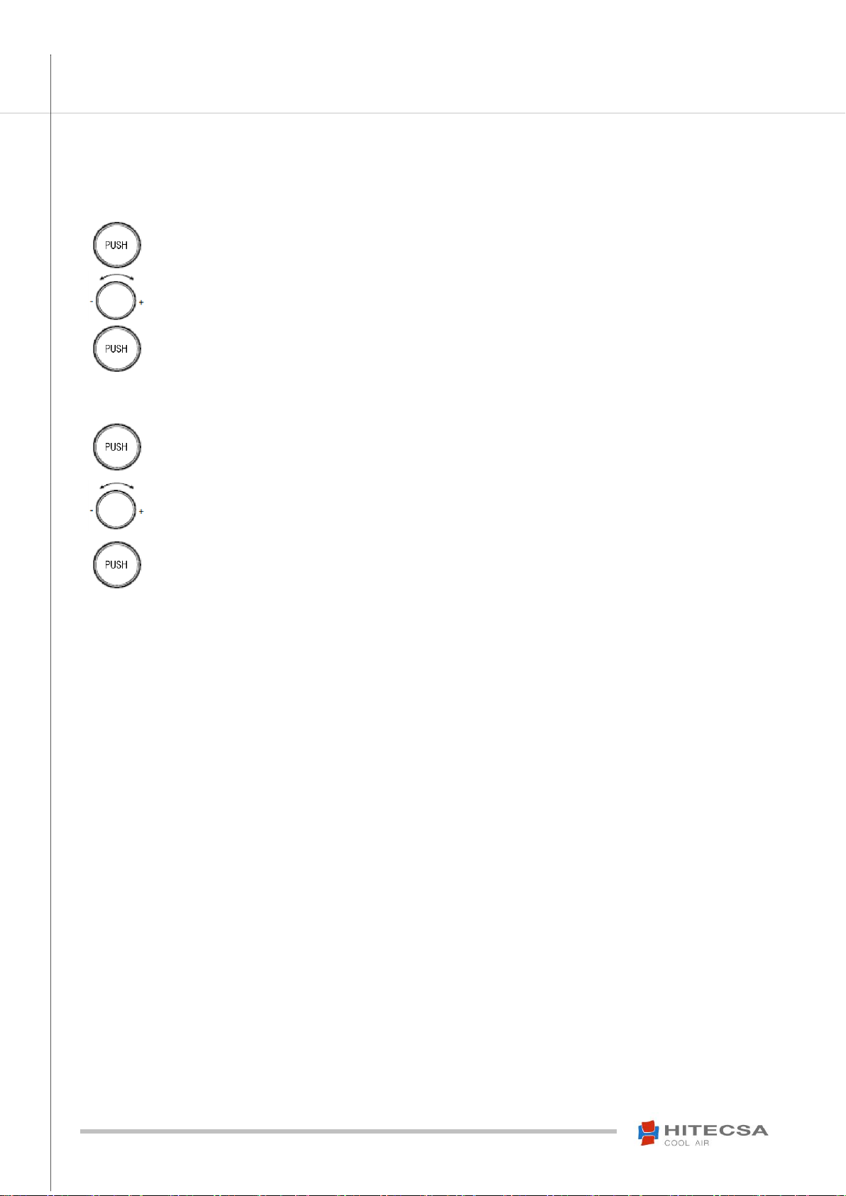
ADDRESS PARAMETER CONFIGURATION
Press the central button several times until ADDR
appears.(Supervision is not activated if these
characters are not displayed).
Turn the central button to select the direction
(1-200).
Press the central button once to confirm.
BAUD (RATE) PARAMETER CONFIGURATION
Press the central button several times until BAUD
appears.
Turn the central button to select the speed.
(0, 1, 2, 3, 4)
0 → 1200
1 → 2400
2 → 4800
3 → 9600
4 → 19200
Press the central button once to confirm.

11
USM_TH-TUNE Aire-Aire y Agua-Aire_207960_181005_EN
TH-TUNE
Packaged Air-Air and Water-Air units
Subject to modification without prior notice.Translated from the original manual in Spanish.
Other manuals for TH-TUNE
1
Table of contents
Other Hitecsa Thermostat manuals


Popular Thermostat manuals by other brands

Watts Industries
Watts Industries Thermostat user guide

Dettson
Dettson R02P032 Installation instructions and homeowner's manual

Drayton
Drayton Lifestyle LP111Si User instructions

Tekmar
Tekmar tekmarNet 552 Installation & operation manual

Fidure
Fidure A2132FAC user guide

ComfortNET
ComfortNET Touchscreen Thermostat System Homeowner user guide

Webee
Webee Smart Thermostat Getting started

ApenGroup
ApenGroup SMART WEB Series Operating, Installation and Programming Manual

Heltun
Heltun HE-ZW-THERM-FL1 user manual

TemperZone
TemperZone SAT-1 User operating instructions

C.O.K.
C.O.K. RDF 642 2-00 Series manual

Honeywell
Honeywell T8095A/191108AJ owner's manual


