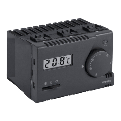
Perry Electric 1TX CR028WIFI Guide

• Wireless connection to the Smartbox
• Equipped with a back-lit LCD display with
"White-LED” technology
• Weekly programming
• Battery powered (not included)
• “All glass” finish for a pleasant and modern design
• Easy to program via APP
Wi-Fi PROGRAMMABLE THERMOSTAT
Installation and use manual
PE - DERXPE005 EN 01/18
ENGLISH

CONTENTS
WARNINGS
..........................................................................................................................................
pag. 3
KEYS
.....................................................................................................................................
pag. 4
DISPLAY pag. 5
INSTALLATION
....................................................................................................................................
pag. 6
ELECTRICAL CONNECTIONS
...............................................................................................................
pag. 8
................................................................................................................................
SECURING OR REMOVING THE PROGRAMMABLE THERMOSTAT FROM THE WALL BASE
......
BATTERIES FLAT OR ALMOST FLAT WARNING
INSERTING OR REPLACING BATTERIES
...................................................................
.............................................................................................
PROGRAMMABLE THERMOSTAT ASSOCIATION TO SMARTBOX
pag. 9
pag. 10
pag. 10
pag. 11
pag. 12
...................... ................................
THE PROGRAMMABLE THERMOSTAT CAN OPERATE IN 3 DIFFERENT MODES
PROGRAMMABLE THERMOSTAT TECHNICAL SPECIFICATIONS
SIMPLIFIED EU DECLARATION OF CONFORMITY
.........................
............................................................
.....................................................................
pag. 14
pag. 16
OPERATIONS CARRIED OUT DIRECTLY BY PROGRAMMABLE THERMOSTAT pag. 13
........................................
2

WARNINGS
DISPOSAL OF ELECTRICAL & ELECTRONIC EQUIPMENT
This symbol on the product or its packaging to indicates that this product shall not be treated as household waste.
Instead, it shall be handed over to the applicable collection point for the recycling of electrical and electronic equipment, such as for example:
- sales points, in case you buy a new and similar product;
- local collection points (waste collection centre, local recycling center, etc...).
By ensuring this product is disposed of correctly, you will help prevent potential negative consequence for the environment and human health,
which could otherwise be caused by inappropriate waste handing of this product.
The recycling of materials will help to conserve natural resources. For more detailed information about recycling of this product, please contact
your local city office, your house hold waste disposal service or the shop where you purchased the product. 3
The installation and electrical connection of the
devices and appliances must be implemented by
qualified personnel and in conformity with current laws
and regulations.
Carefully read the instruction manual before using the
product as it provides important guidelines regarding
safety, installation and use. The instruction manual
must be preserved with care for future reference.
Ensure the product is intact once it is removed from its
packaging.
Packaging components (any plastic bags, PVC suspensions,
etc.) must be kept out of reach of children.
The thermostat is not intended for use byprogrammable
persons (including children) with reduced physical, sensory
or mental capabilities, or by those with a lack of experience
and knowledge of the instructions, unless they are
supervised or have received the necessary instructions
concerning use of the device by a person responsible for their
safety. Children should be supervised to ensure that they do
not play with the device.
If necessary, clean the thermostat with aprogrammable
slightly damp cloth.
Important: for the system modes and
operation of the WIFI temperature control
system and for correct installation, also see
the specific manual of the smartbox and of the
APP.
Radio frequency waves emitted by the
wireless thermostat are notprogrammable
a risk to human or animal health.
Important: the manufacturer reserves the
right to introduce any technical and/or
constructive changes deemed necessary,
with no prior notice.
Important: the manufacturer shall not, under
any circumstances, be liable if the products
fail to operate due to the interruption of the
internet network or unavailability of these
resources: Cloud, Server, Portal.
Important: internet access costs are charged
to users according to the rates of their mobile
phone provider.
INTERNET
off line

LEGENDA DISPLAY
KEYS
Programmable
thermostat
OFF
Increase
temperature
Decrease
temperature
Link
(connection)
To activate the keyboard is
necessary press any key
(Keys and display backlight)
4

Current
time
Battery at
Key
lock
Not
used
Not
used
Away
mode
Not
used
Programmable thermostat
coupled and communicating
Programmable thermostat
coupled but not
communicating
Cooling mode
Detected room temperature
Set
temperature
Heating mode
Operation
from entered
program
Connected utility on
(e.g. Boiler)
DISPLAY
Override operation
Days of
the week
5

DENSE VEGETATION
trees, hedges, shrubs, etc.
radio range reduction of 10%÷25%
WOOD OR
PLASTERBOARD WALLS
radio range reduction of 10%÷30%
BRICK OR STONE WALLS
radio range reduction of 40%÷60%
CONCRETE WALLS
radio range reduction of 50%÷70%
METAL WALLS and/or FLOORS
radio range reduction of 65%÷90%
During installation, some precautions must be taken in order not to limit or, in some cases, inhibit the range of the radio waves
between Smartbox and Programmable thermostat, in particular:
- install the appliance away from metal furniture or structures which could alter or screen propagation of radio signals;
- make sure that there are no electrical or electronic devices (television, microwave oven, etc.) within a range of at least 1 m
from the appliance.
Note: if there are no obstacles between the Programmable thermostat and Smartbox, the “open air” range is approximately
200 m; indoors with the presence of walls, the range is approximately 30m (see “technical data”).
Radio range decreases significantly when the
components are interposed between the obstacles.
This attenuation varies in different degrees
depending on the type of material the walls or
barriers to cross are made of.
The presence of noise or electromagnetic
interference sources can also reduce the indicated
radio range.
Below are some examples of mitigation related to
materials, which impact on the "Free air" range
declared above.
6
INSTALLATION
Radio range warnings

INSTALLATION
88
128
INSTALLATION EXAMPLE
Install the thermostat preferably at a height ofprogrammable
1.50 to 1.60 m from the floor, far from sources of heat, air inlets,
doors or windows and anything that may alter its operation.
FASTENING THE WALL BASE
To ensure the thermostat is fittedprogrammable
correctly to the wall-mounted base, the latter must not be
bent due to the screws being tightened too much to the
rounded or rectangular recessed box.
!Switch off mains power 230V~ to device
!Fasten the base of the thermostat with theprogrammable
screws supplied: to the wall, to the rounded or rectangular
recessed box via the relative paired holes A.
E
DIMENSIONS
h 1,5 m
26
A
A
C
D
B
Wall mounted - onto a recessed rounded box
or with a rectangular 3 module box.
Programmable thermostat installation: independent fixed
7
A- base fastening holes: wall-mounted, round or rectangular
recessed box
B- wire passage from corrugated tubes, round or rectangular
recessed box
C- thermostat hooking teethprogrammable
D- thermostat fastening slotprogrammable
E- screws to fasten the wall base to the rectangular or round
recessed box.

Important: the installation and electrical connection of the devices and appliances must be implemented by qualified
personnel and in conformity with current laws and regulations. The manufacturer declines all liability in connection
with the use of products subject to special environmental and/or installation standards.
Disconnect the 230V~ mains voltage
that powers the devices to be controlled
Examples of electrical connections
!connect the device to be controlled to the terminals:
1- common (C)
- normally closed contact (NC)2
- normally open contact (NO)3
Connection to a boiler Connection to a motorized valve
Relay terminals
BOILER
NO
NC
C
1239876
L
N230V~
NO
NC
C
1239876
AUX 1 AUX 2
LOAD
M
230V~
NL
230V~
opens
closes
ELECTRICAL CONNECTIONS
8

1°
3°
2°
FASTEN OR REMOVE THE THERMOSTAT TO/FROM THE WALL-MOUNTED BASEPROGRAMMABLE
E
C
D
C
Hook the thermostat to the wall base in teeth .programmable C
Then press the thermostat at the bottom to complete fastening in slot .programmable D
DUnhook the thermostatprogrammable
from the wall base, using a screwdriver
in the specific slot ( ) in the lower part ofD
the device for leverage, then turn to
remove it.
Removing the
thermostatprogrammable
from the wall base
9
After having made the electrical connections:
!Apply the terminal cover to the base, securing
it to hook .E
!To remove the cover, use a small screwdriver
on hook for leverage.E

ONLY USE GOOD QUALITY ALKALINE BATTERIES
(Duracell or Energizer batteries are reco ended)mm
Attention: battery life may be more than 2 years.
However, it is recommended to replace them at
least every 24 months to avoid them running out
when you are away (e.g. Christmas holidays,
etc.)
Dispose of flat batteries in appropriate
containers and as required by the
environmental protection regulations.
3V dc power supply
2 x 1,5Vdc LR6 - AA (not included)
SIGNALLING BATTERIES LOW OR DOWN
When the symbol blinks, this indicates that the batteries are running out
and as from this moment there are 15 days to replace them.
All thermoregulation is suspended and all settings are saved to be restored
when the new batteries are inserted.
Note: the backlight of the display is automatically deactivated.
If the discharged batteries are not replaced within this time the display will
completely turn off.
INSERTING OR REPLACING BATTERIES
Unhook the thermostat from the wall base (see previousprogrammable
paragraph)
Insert the batteries, respecting the polarity.
Hook and fix the thermostat to the wall baseprogrammable
(see previous paragraph)
10

PROGRAMMABLE THERMOSTAT ASSOCIATION TO SMARTBOX
The programmable thermostat must be coupled to the Smartbox with the specific PERRY PROGRAMMABLE
THERMOSTAT APP. Instead of association via APP, you may associate the programmable thermostat by pressing
the association key on the Smartbox for 3 seconds and the two external buttons ( + ) on the programmable
thermostat for 3 seconds.
If the aerial symbol appears on the display of the programmable thermostat, it means that it has been associated
If the symbol of the crossed-out aerial appears on the display of the programmable thermostat, it means that it has
been associated correctly but there are communication problems with the Smartbox. Make sure that the two devices are
not too far apart or that there are no objects or walls significantly shielding the radio signal.
If no aerial symbol appears on the programmable thermostat, repeat the operation above.
correctly to the Smartbox.
11

THE PROGRAMMABLE THERMOSTAT CAN OPERATE IN 3 DIFFERENT MODES:
Auto: the set temperature changes automatically depending on the program set viaAPP.
.
: this is a temporary mode activated when the temperature is modified directly by the user; the changeOverride
remains valid until the next programmed change.
OFF: the programmable thermostat was switched off directly by the user, it suspends all temperature control and can
be remote-controlled.
If the programmable thermostat is not associated to a Smartbox, it cannot operate inAuto mode.
by modifying the temperature using the arrows the override symbol appears on the display.
Override mode:
To exit the override mode, wait for the next programmed change, or press the key twice.
OFF mode:
Pressing the key suspends all temperature control, the programmable thermostat can be remote
controlled viaAPP.
To exit the OFF mode, press again and the programmable thermostat will go back toAuto mode.
12

OPERATIONS CARRIED OUT DIRECTLY BY PROGRAMMABLE THERMOSTAT
Key lock
To lock the keyboard, simultaneously press the keys for 3 seconds, and the
lock symbol will appear on the display.
To unlock the keyboard, simultaneously press the keys for 3 seconds, and the
lock symbol will disappear from the display.
Reset
To restore the programmable thermostat to default conditions, perform the reset
operation by simultaneously pressing the keys: for 3 sec.
The text appears on the display. Press to confirm the .reset
The programmable thermostat eloses association with the smartbox and
programming is cancelled.
Note: the programmable thermostat will also be removed from the APP
(see APP instructions)
Default settings:
·Programmable thermostat mode: OFF
·Set temperature: 18°C
·No RF radio connection (no association to smartbox)
·type: Heating
·Type of ON/OFF differential temperature control: Hysteresis 0.5°C
·Descaling pump: OFF
·Away OFFSET: 2°C
13

PROGRAMMABLE THERMOSTAT TECHNICAL SPECIFICATIONS
Power supply by 2x , over 2 year duration1.5V alkaline type AA batteries·
LCD backlit·
4 keys, with lock option·
·Type of action, disconnection and appliance: 1 / BU / Electronic.
·Type of output: relay with contact in COM / NO / NC exchange, potential free - max 5(3)A/250V~
·Cross-section of the wires to the terminals: 1.5 mm² ÷ 2.5 mm²
·Rated impulse voltage: 4 kV
·Software: class A
·Radio emission: the appliance intentionally emits radio waves at a frequency of 869,525 MHz,
with a max. power 0.5mW e.r.p.
·Integrated PCB aerial, indicated range 200 m outdoors, approximately 30 m indoors
·Non-volatile memory to store settings
·Temperature scale: °C (Celsius)
, with 1 minute resolution, precision +/- 1 minuteWeekly programming·
·10 programmable temperature levels a day
·Set temperature: 0 ÷ 35 °C, at 0.5 °C steps
·Room temperature measurement: 0 ÷ +50 °C, resolution 0.1 °C, precision +/- 0,5 °C
·Operating temperature 0 ÷ +45 °C
·Storage temperature: -10 °C ÷ +60 °C
·Temperature control mode:
- ON/OFF differential (default setting) Hysteresis settable at 0.2 °C / 0.4 °C / 0.8 °C / 1.6 °C
- PID modulating proportional settable 10 minutes / 15 minutes / 20 minutes / 25 minutes
ERP Energy classification Reg. EU 811/2013:·
-in ON/OFF differential mode = ERP Class I 1%
- in modulating proportional mode = ERP Class IV 2%
Insulation class: Class II (pic.)·
Protection rating: IP30·
Rate of pollution: Normal·
Descaling pump (2 minutes to move the pump if not activated the week before)·
·Operating mode: Heating (default setting) / Cooling
·Away OFFSET: 0.0 / 0.5 / 1.0 / 1.5 / 2.0 / 2.5 / 3.0 / 3.5 / 4.0 / 4.5 / 5.0° C
·Temperature for marble test: terminals, printed circuit 125° C; enclosure 75° C
14

15

EU SIMPLIFIED CONFORMITY DECLARATION
The manufacturer declares that the type of radio
equipment listed below complies with Directive
2014/53/EU (RED).
The full text of the EU Declaration of Conformity is
available at the following Internet address:
http://www.perry.it/it/dichiarazioni.aspx
F. A . Q .
(Frequently Asked Questions and Inconsistent Resolutions)
consult the FAQ on page:
or else access it using the QR code:
http://perry.it/it/prodotto/1tx-cr028wifi.aspx
Via Milanese, 11
22070 VENIANO (Como) - ITALY
Tel. +39 031.8944.1 Fax +39 031.931848
1TXCR028WIFI V001
PERRY ELECTRIC S.r.l.
www.perry.it
Manufacturer, Fabricat , Fabbricante, Fabricante:, Fabrikant
Type , Tipo:, Typen
Table of contents
Other Perry Electric Thermostat manuals

Perry Electric
Perry Electric Recess Series User manual

Perry Electric
Perry Electric TE540 User manual

Perry Electric
Perry Electric V002 Series Guide

Perry Electric
Perry Electric TE541 User manual

Perry Electric
Perry Electric RECESS Series User manual

Perry Electric
Perry Electric MODULE Series User manual

Perry Electric
Perry Electric TE542 User manual