hivolt HC52 Series User manual
HC52 Series
© 2019 hivolt.de - Subject to change without notice, errors expected HC52_E 08/2019 Page 1 of 7
hivolt.de GmbH & Co. KG
Oehleckerring 40 ∙D-22419 Hamburg ∙Germany ∙+49 40 537122-0 ∙+49 40 537122-99 ∙[email protected] ∙www.hivolt.de
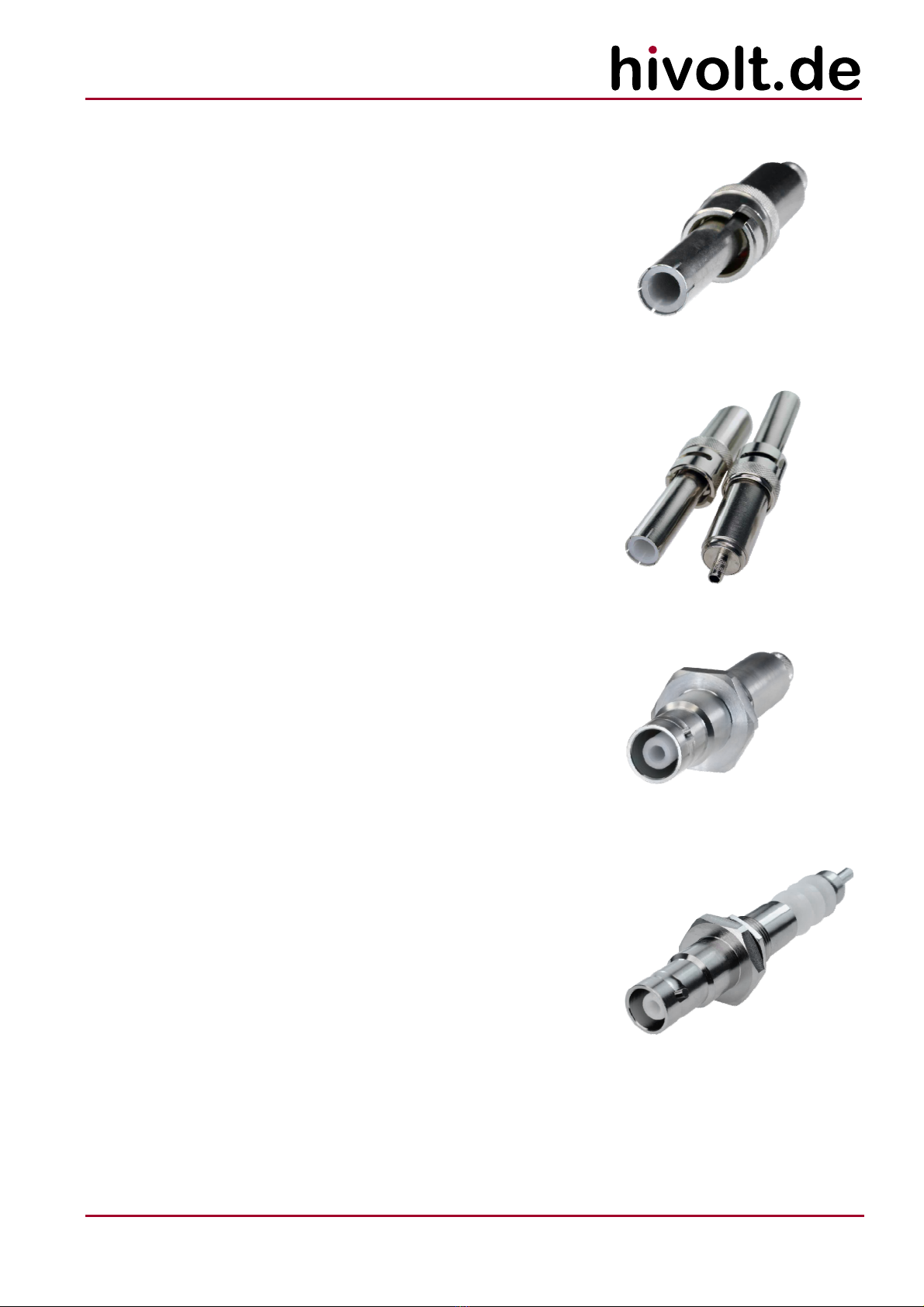
20kV - STRAIGHT COAXIAL CONNECTOR SERIES
FEATURES
−Rated Voltage 20kVDC
−Recessed contacts
−Coaxial design
−Bayonet Coupling
−Intermateable with industry standard
20kV coaxial connectors
−Completed cable assemblies available
−RoHS compliant
APPLICATIONS
−Instrument High Voltage Connections
−High voltage power supplies / amplifiers
−Medical electronics
−Nuclear instrumentation
−Test and measurement equipment
−High voltage laboratory wiring
−General high voltage testing
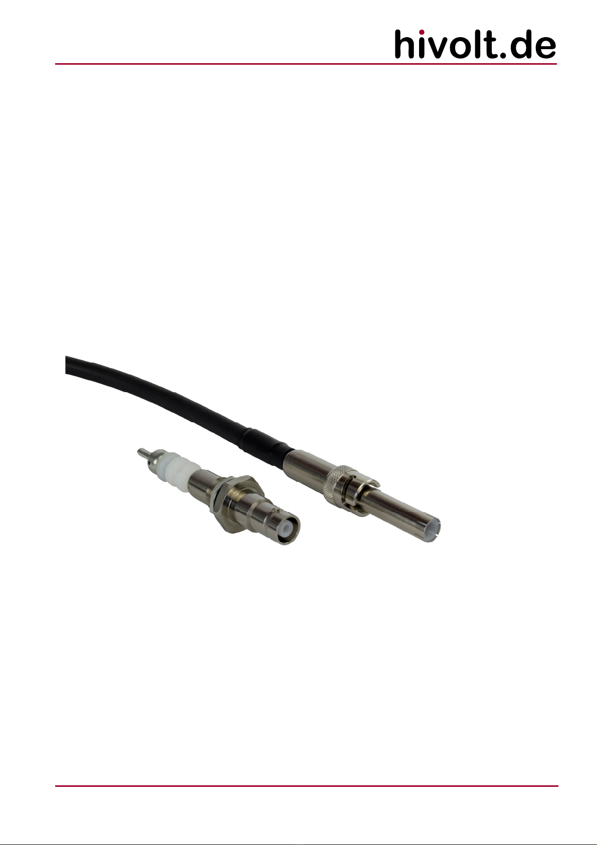
20kV reverse polarity coaxial high voltage connectors designed to
minimize the risk of electrical shock to personnel through the use of
recessed contacts. Both the cable connectors and the bulkhead
receptacles have recessed contacts and will stand off the rated voltage in
unmated condition.
The front mount receptacles are hermetically sealed.
The straight crimp cable plug HC52P and the rear mount crimp
receptacles HC52RB are compatible with RG 213 or RG 214 coaxial cable.
The straight cable plug HC52P-HTV30S is compatible with our 30kV rated
HTV-30S-22-2 coaxial cable.
A suitable crimping tool is available on request.
The connectors are RoHS compliant.
The connectors should never be mated or unmated when energized.
Please see the HC51 series for 10kVDC models.
HC52 series connectors are not intermateable with SHV or HC51 series
connectors.
SPECIFICATIONS
Operating voltage: max. 20kVDC (at sea level)
Test voltage: 30kVDC
Impedance: non constant
Insulation resistance: 1000GΩ
Center contact resistance: ≤3mΩ
Outer contact resistance: ≤2mΩ
Operating temperature: -55 to +85°C
Leak rate < 1x10⁻⁶ mbar*l/s @ 1bar differential
pressure
(applies to front mount bulkhead
receptacles only)
Ratings listed above apply to clean mated connector pairs in standard atmospheric conditions. When connectors are used
in an adverse environment (such as high temperature, humidity, pollution content, extreme mechanical exposure, etc.) the
connector should be derated. The fitness for use must be proved by extended operational tests.

HC52 Series
© 2019 hivolt.de - Subject to change without notice, errors expected HC52_E 08/2019 Page 2 of 7
hivolt.de GmbH & Co. KG
Oehleckerring 40 ∙D-22419 Hamburg ∙Germany ∙+49 40 537122-0 ∙+49 40 537122-99 ∙[email protected] ∙www.hivolt.de
MODEL OVERVIEW - PLUGS
Part Number
Description
Termination
Center
Contact
Contact Pin
Material/
Plating
Insulator
Material Body
Material/
Plating
Gasket
Material Weight
HC52P-213 /-214
Straight Crimp Cable Plug
Crimp
Beryllium
Copper/
Au over Ni
over Cu
High Density
PE Brass/
Ni over Cu Silicone 51.2g
HC52P-HTV30S
Straight Crimp Cable Plug
Crimp Beryllium
Copper/
Au over Ni
over Cu
High Density
PE Brass/
Ni over Cu Silicone 51.2g
MODEL OVERVIEW - RECEPTACLES
Part Number
Description
Termination
Center
Contact
Contact Pin
Material/
Plating
Insulator
Material Body
Material/
Plating
Gasket
Material Weight
HC52RB-213
Rear Mount Bulkhead
Crimp Receptacle
Crimp Brass/
Au over Ni
over Cu
High Density
PE Brass/
Sn-Zn-Cu
Alloy over
Cu
Silicone
HC52RB-A
Front Mount Bulkhead
Receptacle (long insulator)
Solder Brass/
Au over Ni
over Cu
High Density
PE Brass/
Sn-Zn-Cu
Alloy over
Cu
Silicone 58g
HC52RB-B
Front Mount Bulkhead
Receptacle (short insul.)
Solder Brass/
Au over Ni
over Cu
High Density
PE Brass/
Ni over Cu Silicone 61g
HC52 Series
© 2019 hivolt.de - Subject to change without notice, errors expected HC52_E 08/2019 Page 3 of 7
hivolt.de GmbH & Co. KG
Oehleckerring 40 ∙D-22419 Hamburg ∙Germany ∙+49 40 537122-0 ∙+49 40 537122-99 ∙[email protected] ∙www.hivolt.de
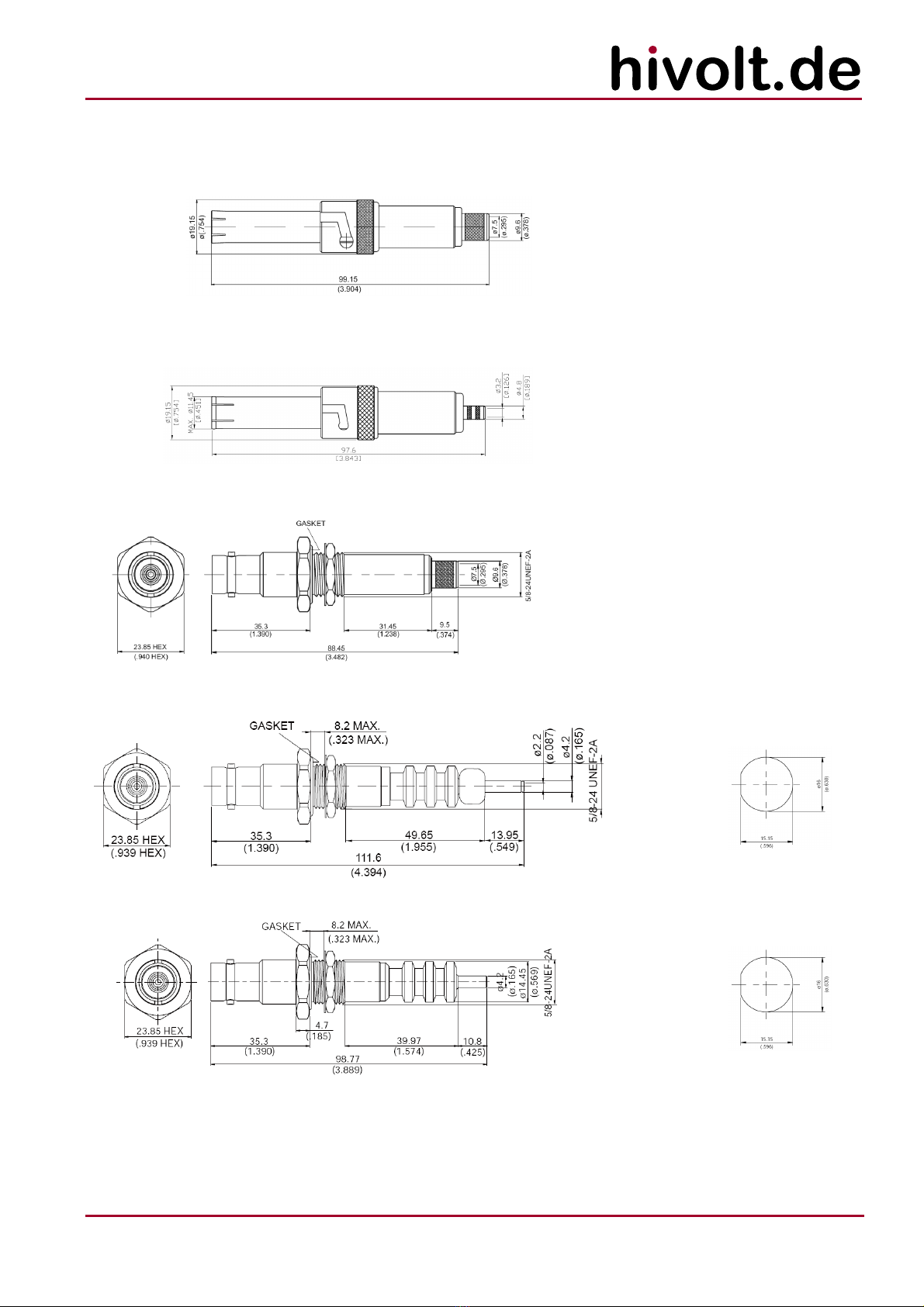
DIMENSIONS
HC52P-213 /-214
HC52P-HTV30S
HC52RB-213
HC52RB-A
PANEL CUT-OUT
HC52RB-B
PANEL CUT-OUT
−All dimensions are in mm (inch); drawings not to scale.
−All values and dimensions without given tolerances are nominal.
HC52 Series
© 2019 hivolt.de - Subject to change without notice, errors expected HC52_E 08/2019 Page 4 of 7
hivolt.de GmbH & Co. KG
Oehleckerring 40 ∙D-22419 Hamburg ∙Germany ∙+49 40 537122-0 ∙+49 40 537122-99 ∙[email protected] ∙www.hivolt.de
ORDERING INFORMATION
20kV Straight Crimp Cable Plug (female) for RG 213 HC52P-213
20kV Straight Crimp Cable Plug (female) for RG 214 HC52P-214
20kV Straight Crimp Cable Plug (female) for HTV-30S-22-2 HC52P-HTV30S
20kV Rear Mount Bulkhead Crimp Receptacle (male) for RG 213 HC52RB-213
20kV Front Mount Bulkhead Receptacle (male, long insulator) HC52RB-A
20kV Front Mount Bulkhead Receptacle (male, short insulator) HC52RB-B
CRIMP TOOLS
Ergonomic blank crimp tool frame HC-CR-2
suitable for crimp inserts HC-CR-DIE-A, HC-CR-DIE-B, HC-CR-DIE-C
Crimp Insert Hex 5.5mm, 5.9mm, Square 0.98mm, 1.6mm, 2.4mm HC-CR-DIE-B
Crimp Insert Hex 2.55mm, 3.3mm, 10.7mm, Square 1.6mm, 2.4mm HC-CR-DIE-C
Bespoke ready-to-use high voltage cable assemblies based on different high voltage cable types are available. The cable
assemblies are fully tested. Please contact hivolt.de for details.
Examples:
Cable: HTV-30S-22-2; Length: 2m; HC52P-HTV30S plug assembled on both ends HCA-020-H52C-002-H52C-T
Cable: RG 213; Length: 10m; HC52P-213 plug assembled on one end, HCA-020-H52A-010-H52R-X
HC52RB-213 receptacle on the other end
Disclaimer
The information given in this data sheet is technical data, not assured product characteristics. It has been carefully checked and is believed to be accurate; however, no responsibility is
assumed for inaccuracies. The user has to ensure by adequate tests that the product is suitable for his application regarding safety and technical aspects.
hivolt.de GmbH & Co. KG does not assume any liability arising out of the application or use of any product described.
Safety Advice
Design, installation and inspection of machinery and devices carrying high voltage require accordingly trained and qualified personnel. Appropriate safety rules and directives must be
complied with.
Improper handling of high voltage can mean severe injuries or death and may cause serious collateral damage!
HC52 Series
© 2019 hivolt.de - Subject to change without notice, errors expected HC52_E 08/2019 Page 5 of 7
hivolt.de GmbH & Co. KG
Oehleckerring 40 ∙D-22419 Hamburg ∙Germany ∙+49 40 537122-0 ∙+49 40 537122-99 ∙[email protected] ∙www.hivolt.de
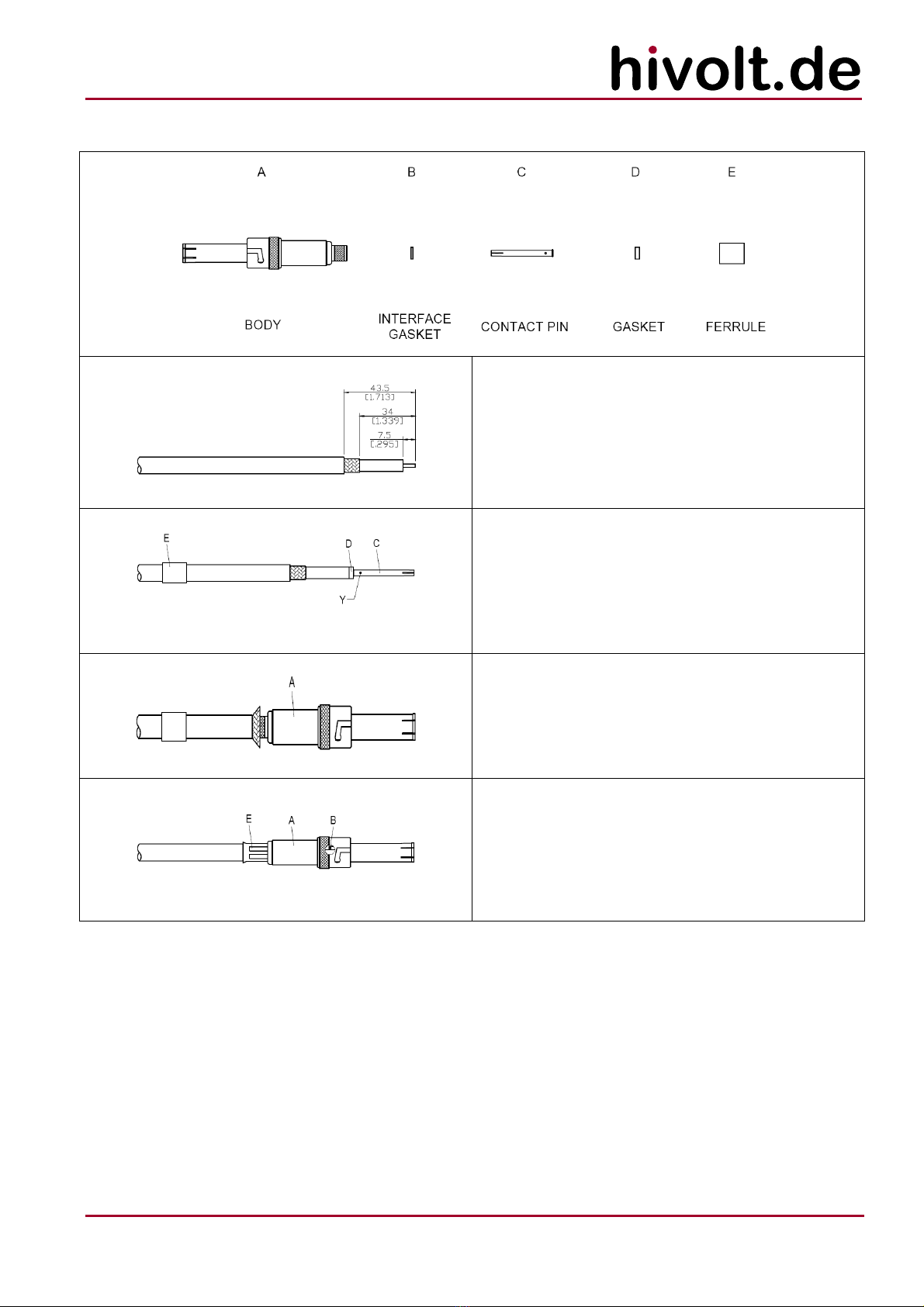
CABLE ASSEMBLY INSTRUCTIONS HC52P-213 AND HC52P-214
Step 1: strip as shown.
Make sure not to scratch the isolation!
Step 2: slide ferrule “E” over cable.
Step 3: put gasket "D" and pin "C" on center conductor and
solder in "Y".
Gasket must be under compression after soldering
is completed.
Step 4: loosen braiding and slide connector "A" in place.
Step 5: slide ferrule "E" towards the connector "A" and
crimp.
Use 10.7mm/0.421" hex crimp die insert
HC-CR-DIE-C.
Step 6: Install interface gasket B over contact pin.
All dimensions are in mm [inch]; drawings not to scale

HC52 Series
© 2019 hivolt.de - Subject to change without notice, errors expected HC52_E 08/2019 Page 6 of 7
hivolt.de GmbH & Co. KG
Oehleckerring 40 ∙D-22419 Hamburg ∙Germany ∙+49 40 537122-0 ∙+49 40 537122-99 ∙[email protected] ∙www.hivolt.de
CABLE ASSEMBLY INSTRUCTIONS HC52P-HTV30S
Step 1: strip as shown.
Make sure not to scratch the isolation!
Step 2: slide ferrule "C" over cable.
Step 3: put pin "B" on center conductor and solder in "Y".
Step 4: loosen braiding and slide connector "A" in place.
Step 5: slide ferrule "C" towards the connector "A" and
crimp.
Use 5.9mm/0.232inch hex crimp die insert
HC-CR-DIE-B.
All dimensions are in mm [inch]; drawings not to scale

HC52 Series
© 2019 hivolt.de - Subject to change without notice, errors expected HC52_E 08/2019 Page 7 of 7
hivolt.de GmbH & Co. KG
Oehleckerring 40 ∙D-22419 Hamburg ∙Germany ∙+49 40 537122-0 ∙+49 40 537122-99 ∙[email protected] ∙www.hivolt.de
CABLE ASSEMBLY INSTRUCTIONS HC52RB-213
Step 1: strip as shown.
Make sure not to scratch the isolation!
Step 2: slide ferrule”D” over cable.
Step 3: put and gasket "C"and pin "B" on center conductor
and solder in "Y".
Gasket must be under compression after soldering
is competed.
Step 4: loosen braiding and slide connector "A" in place.
Step 5: slide ferrule "D" towards the connector "A" and
crimp.
Use 10.7mm/0.421" hex crimp die insert
HC-CR-DIE-C.
All dimensions are in mm [inch]; drawings not to scale
This manual suits for next models
6
Table of contents
Other hivolt Cables And Connectors manuals


