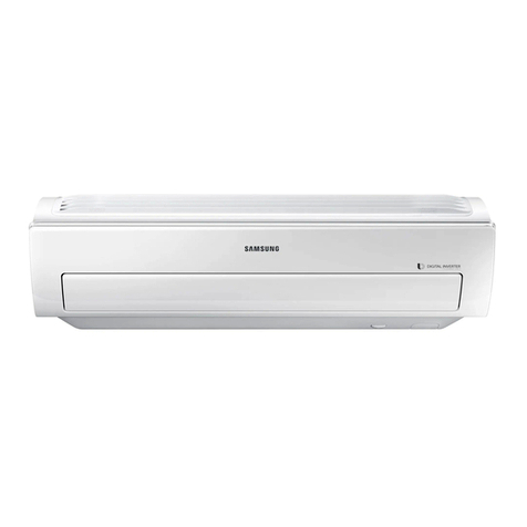
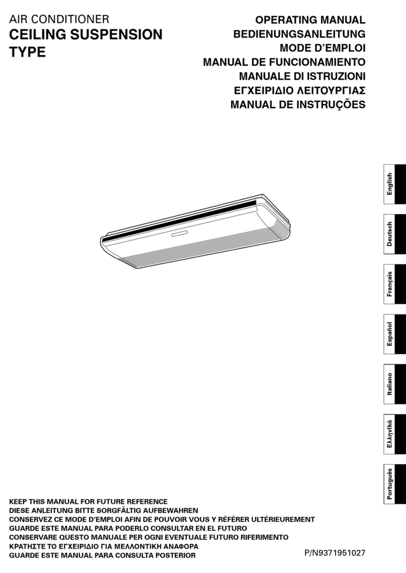
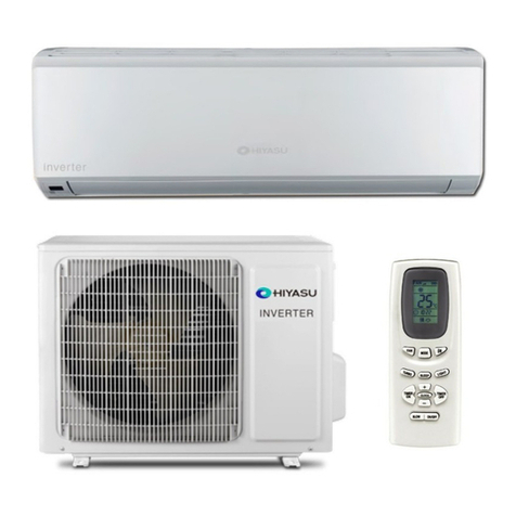
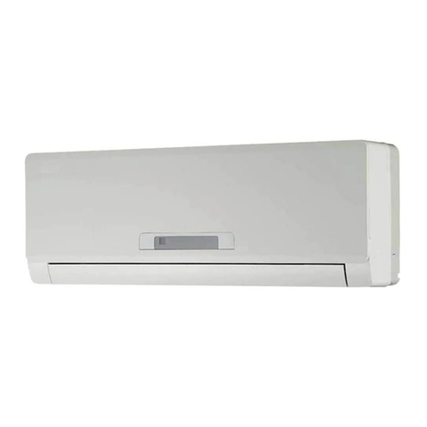
Hiyasu HSE 7 TW03 I/HOE 7 TW03 I User manual

Indoor Unit/Outdoor Unit
INVERTER ROOM AIR CONDITIONER
KEEP THIS OPERATION MANUAL
FOR FUTURE REFERENCE
No.0010548000
HSE 7 TW03 I/HOE 7 TW03 I
HSE 10 TW03 I/HOE 10 TW03 I
HSE 13 TW03 I/HOE 13 TW03 I
HSE 14 TW03 I/HOE 14 TW03 I
HSE 18 TW03 I/HOE 18 TW03 I
HME 10 TW03 I/HOME 20 TW03 I
PLEASE READ THIS OPERATION MANUAL
BEFORE USING THE AIR CONDITIONER.

HSE 7 TW03 I/HOE 7 TW03 I
HSE 10 TW03 I/HOE 10 TW03 I
HSE 13 TW03 I/HOE 13 TW03 I
HSE 14 TW03 I/HOE 14 TW03 I
HSE 18 TW03 I/HOE 18 TW03 I
HME 10 TW03 I/HOME 20 TW03 I

Indoor Unit/Outdoor Unit
HSE 7 TW03 I/HOE 7 TW03 I
HSE 10 TW03 I/HOE 10 TW03 I
HSE 13 TW03 I/HOE 13 TW03 I
HSE 14 TW03 I/HOE 14 TW03 I
HSE 18 TW03 I/HOE 18 TW03 I
HME 10 TW03 I/HOME 20 TW03 I

KEEP THIS OPERATION MANUAL
FOR FUTURE REFERENCE
INVERTER ROOM AIR CONDITIONER
Indoor Unit/Outdoor Unit
HSE 7 TW03 I/HOE 7 TW03 I
HSE 10 TW03 I/HOE 10 TW03 I
HSE 13 TW03 I/HOE 13 TW03 I
HSE 14 TW03 I/HOE 14 TW03 I
HSE 18 TW03 I/HOE 18 TW03 I
HME 10 TW03 I/HOME 20 TW03 I
PLEASE READ THIS OPERATION MANUAL
BEFORE USING THE AIR CONDITIONER.

En-2
Cautions ..............................................................
Parts and functions............................................
Operation ..........................................................
Maintenance ....................................................
Trouble shooting .............................................
Contents
3-6
7-11
12-20
21-26
27-28

For the purpose of the safety,the air conditioner
must be properly grounded in accordance
with specifications.
Always remember to unplug the air
conditioner before openning inlet grill. Never
unplug your air conditioner by pulling on
the power cord. Always grip plug firmly and
pull straight out from the outlet.
All electrical repairs must be carried out
by qualified electricians. Inadequate repairs
may result in a major source of danger for
the user of the air conditioner.
Do not damage any parts of the air
conditioner that carry refrigerant by piercing
or perforating the air conditioner's tubes
with sharp or pointed items , crushing or
twisting any tubes , or scraping the coatings
off the surfaces. If the refrigerant spurts
out and gets into eyes , it may result in
serious eye injuries.
En-3
Cautions
Disposal of the old air conditioner
Before disposing an old air conditioner that
goes out of use, please make sure it's
inoperative and safe. Unplug the air
conditioner in order to avoid the risk of
child
entrapment.
It must be noticed that air conditioner
system contains refrigerants, which require
specialized waste disposal. The valuable
materials contained in a air conditioner
can
be recycled. Contact your local waste
disposal center for proper disposal of an
old air conditioner and contact your local
authority or your dealer if you have any
question. Please ensure that the pipework
of your air conditioner does not get
damaged
prior to being picked up by the relevant
waste disposal center, and contribute to
environmental awareness by insisting on
an appropriate, anti-pollution method of
disposal.
Disposal of the packaging of your
new air conditioner
All the packaging materials employed in
the
package of your new air conditioner may
be
disposed without any danger to the
environment.
The cardboard box may be broken or cut
into
smaller pieces and given to a waste paper
disposal service. The wrapping bag made of
polyethylene and the polyethylene foam pads
contain no fluorochloric hydrocarbon.
All these valuable materials may be taken
to a waste collecting center and used again
after adequate recycling.
Consult your local authorities for the name
and address of the waste materials
collecting centers and waste paper disposal
services nearest to your house.
Safety Instructions and Warnings
Before starting the air conditioner, read the
information given in the User's Guide
carefully. The User's Guide contains very
important observations relating to the
assembly , operation and maintenance of
the air conditioner.
The manufacturer does not accept
responsibility for any damages that may
arise due to non-observation of the following
instruction.
Damaged air conditioners are not to be
put into operation. In case of doubt, consult
your supplier.
Use of the air conditioner is to be carried
out in strict compliance with the relative
instructions set forth in the User's Guide.
Installation shall be done by professional
people, don't install unit by yourself.

The machine is adaptive in following
situation
Cooling
Heating
Indoor
Indoor
Outdoor
Outdoor
Maximum: D.B/W.B 32OC / 23OC
Minimum: D.B/W.B 18OC / 14OC
Maximum: D.B 43OC
Minimum: D.B 18OC
Maximum: D.B 27OC
Minimum: D.B 15OC
Maximum: D.B/W.B 24OC / 18OC
Minimum: D.B -15OC
3G1.5mm2+1X0.75mm2
4G1.5mm2
3G2.5mm2+1X0.75mm2
3G0.75mm2+1X0.75mm2
HME 10 TW03/HOME 20 TW03 I
HSE 7 TW03 I/HOE 7 TW03 I
HSE 10 TW03/HOE 10 TW03 I
HSE 13 TW03 I/HOE 13 TW03 I
HSE 14 TW03 I/HOE 14 TW03 I
HSE 18 TW03 I/HOE 18 TW03 I
En-4
Cautions
Do not obstruct or cover the ventilation
grille of the air conditioner. Do not put
fingers or any other things into the
inlet/outlet and swing louver.
Do not allow children to play with the air
conditioner. In no case should children be
allowed to sit on the outdoor unit.
Specifications
The refrigerating circuit is leak-proof.
1. Applicable ambient temperature range:
2. If the supply cord is damaged, it must
be replaced by the manufacturer or its
service agentor a similar qualified
person. The type of connecting wire is
H05RN-F or H07RN-F.
3. If the fuse on PC board is broken,please
change it with the type of T.3.15A/
250V.
4. The distance between the indoor unit
and the floor should be more than 2m.
5. The wiring method should be in line with
the local wiring standard.
6. After installation, the power plug should
be easily reached.
7. The waste battery should be disposed
properly.
8. The appliance is not intended for use by
young children or infirm persons without
supervision.
10. Young children should be supervised to
ensure that they do not play with the
appliance.
11. The requirement of the power supply
cord.
9. The breaker of the air conditioner should
be all-pole switch(25A), and the distance
between its two contacts should be not
less than 3mm.(only for some models)
12.The wiring diagram is attached inside
the machine.
13.The appliance must be installed on strong
enough supporter.

En-5
Cautions
Please read the following Safety Instructions carefully prior to use.
The instructions are classified into two levels, WARNING and CAUTION according to the
seriousness of possible risks and damages as follows. Compliance to the instructions are
strictly required for safety use.
Safety Instruction
Installation
WARNING
Please call Sales/Service Shop for the Installation.
Do not attempt to install the air conditioner by yourself because improper works may
cause electric shock, fire, water leakage.
CAUTION
Installation in a inadequate place may cause accidents. Do not install in the following place.
Connect the earth
cable.
PROHIBITION PROHIBITION
STRICT
ENFORCEMENT
earthing
Do not install in the
place where there
is any possibility
of inflammable
gas leakage around
the unit.
Do not get the unit
exposed to vapor
or oil steam.
Check proper
installation of the
drainage securely

En-6
When abnormality such as burnt-small found, immediately
stop the operation button and contact sales shop.
Connect power supply cord to the
outlet completely. Use the voltage AC220~230V.
Take care not to damage the
power supply cord.
Do not use power supply cord in
a bundle.
Do not use power supply cord
extended or connected in halfway.
Do not insert objects into the air
inlet or outlet.
Do not try to repair or reconstruct
by yourself.
Do not channel the air flow directly
at people, especially at infants or
the aged.
Do not start or stop the operation
by disconnecting the power supply
cord and so on.
PROHIBITION
PROHIBITION
PROHIBITION
PROHIBITION PROHIBITION
PROHIBITION
OFF STRICT
ENFORCEMENT
STRICT
ENFORCEMENT
Use an exclusive power source with a circuit breaker.
CAUTION
Do not use for the purpose of
storage of food, art work, precise
equipment, breeding or cultivation.
Take fresh air occasionally
especially when gas appliance is
running at the same time.
Do not operate the switch with wet
hand.
Do not pour water onto the unit
for cleaning.
Check good condition of the
installation stand.
Do not install the unit near a fireplace
or other heating apparatus.
Do not place animals or plants in
the direct path of the air flow. Do not place any objects on or
climb on the unit. Do not place flower vase or water
containers on the top of the unit.
PROHIBITIONPROHIBITION
PROHIBITION
PROHIBITION PROHIBITION
PROHIBITION
STRICT
ENFORCEMENT
Cautions
WARNING
STRICT
ENFORCEMENT
ON
OFF
SWING FAN
TEMP
TIMER
MODE
RESET CODE LOCK
POWER/SOFT
AUTO
ON
OFF
H
A
B
ion
Use of Air Conditioner

En-7
Parts and Functions
Operating Panel The test operation switch is also used as an emergency
operation switch.
If the remote controlling device is not available (when the
remote controller is lost or the batteries of the controller
have low charge ), the air conditioning system can be
turned on temporarily.
EMERGENCY OPERATION(MANUAL)SWITCH
TEST OPERATION ( MANUAL ) SWITCH
Use the test operation switch when the room temperature is
below 16°C: do not use in normal operation.
OPERATION MODE INDICATOR
TIMER MODE INDICATOR
The timer mode indicator lights when timer switch of the
remote controller is "ON" or "OFF" position.
POWER INDICATOR
The power indicator lights when the ON/OFF switch of
remote controller is "ON".
The opearation mode indicator lights when the air conditioner
is in operation.
PAGE18
PAGE18
Indoor Unit
For models:
The air flow direction can be
adjusted with the vertical and
horizontal louvers
INLET GRILL
MOLD PROOF
AIR FILTER
LOUVER
VERTICAL LOUVER
AIR PURIFYING FILTER
POWER PLUG
REMOTE SIGNAL
RECEIVER
HORIZONTAL LOUVER
Beeping sound assures successful
signal transmission between
wireless remote controller and the
indoor unit.
For multi-split type,the power
plug is on the outdoor unit.
HSE 7 TW03 I
HSE 10 TW03 I
HSE 13 TW03 I
HSE 14 TW03 I
HME 10 TW03 I

Parts and Functions
Indoor Unit
For models:
En-8
Outdoor Unit
For models:
For model:
For model:HSE 18 TW03 I
HOE 18 TW03 I
For models:
OUTLET
INLET
DRAIN HOSE
CONNECTING PIPING AND
ELECTRICAL WIRING
HOME 20 TW03 I
HOE 13 TW03 I
HOE 14 TW03 I
HOE 7 TW03 I
HOE 10 TW03 I

ON
OFF
SWING FAN
TEMP
TIMER
MODE
RESET CODE LOCK
POWER/SOFT
AUTO
ON
OFF
H
A
B
ion
COOL DRY HEAT
AIR FLOW SPEED SWITCH
TEMPERATURE INDICATOR
En-9
Parts and Functions
Wireless Remote Controller
OPERATION MODE
INDICATOR
AIR FLOW SPEED
INDICATOR
DESIGNATED
PERIOD INDICATOR
AIR FLOW DIRECTION
SWITCH
MODE SWITCH
indicates the current
operating mode.
ON/OFF SWITCH
Indicates the air flow speed
selected by the air flow
speed switch.
When set at "AUTO",micro-
computer selects the
adequate air flow speed
automatically according to
the difference between the
designated temperature and
the room temperature.
Indicates the period set by
the time setting switches.
Starts operation with a press;
stops operation with another
press.
Air flow direction can be
changed vertically (upward
and downward ) by each
press.
Used to select COOL,DRY
and HEAT operation.
The above example of indications is for the purpose of
explanation only and it is different from actual indications.
TIMER MODE INDICATOR
POWER MODE INDICATOR
TIME SETTING SWITCHES
SIGNAL SENDING HEAD
POWER MODE SWITCH
Sends signals to the remote
signal receiver of the indoor
unit.
Lights up when a signal is
sent to the indoor unit.
Indicates the temperature set
by the temperature setting
switches.
OFF: The air conditioner
stops operation after the
designed period.
On:The air conditioner starts
operation after the designed
period.
Used to set soft or super
mode operation.
:
The indicated temperature
increases by 1°C(1.8°F) per
press.
:
The indicated temperature
decreases by 1°C(1.8°F) per
press.
When the switches are
pressed continuously , the
indicator changes quickly.
Used when setting the period
before the operation starts
or stops.
RESET
Used to reset the controller
back to normal condition.
Used to select TIMER ON,
TIMER OFF.
Used when adjusting the air
flow speed.
TIMER MODE SWITCH
TEMPERATURE
SETTING SWITCHES
AUTO
AUTO HI MED LO
Used to lock the buttons and
LCD display.
LOCK INDICATOR
CODE INDICATOR
Used to send code A or B
with a press,A or B will be
displayed on LCD.Please
select A without special
explanation.
Note:
There is no health function with these types.
Multi-split type has no power function.
SIGNAL SENDING
INDICATOR
LOCK
CODE

En-10
Parts and Functions
1
2
3
5
6
14
15
16
17
13
12
11
10
9
8
7
1. Mode display
COOL
DRY
HEAT
2. HEALTH display
3. FAN SPEED display
4.TIMER MODE display
OFF:The air conditioner stops operation
after the designed period.
ON:The air conditioner starts operation
after the designed period.
5. HEATHY BUTTON
Press the "Healthy" button once " "
is displayed now the air conditioners is
operating the healthy function.
Press the "Health" button again then the
healthy operation stops.
6. MODE
Used to select COOL,DRY,HEAT operation.
7. TIMER
8. CODE
Used to select code Aor B with a press,
A or B will be displayed on LCD.Please
select A without special esplanation
9. RESET
Used to reset the controller back to
the normal condition.
10. CODE display
11. SINGNAL SENDING INDICATOR
Lights up when asignal is sent to the unit
12.LOCK display
13. TEMP.display
14. DESIGNATED PERIOD diplay
15. POWER/SOFT display
16. TEMP.
Used to select your desired temp.
17. POWER ON/OFF
Used for unit start and stop.
18. FAN
Used to select fan speed LO,MED, HI,AUTO.
19. SWING
Air flow direction can be changed by each press
20. POWER/SOFT
Used to select power or soft mode operation.
21. LOCK
Used to lock buttons and LCD display.
ion
Brief Introduction to Health Operation
The anion generator in the air conditioner can generate a lot of anion to effectively balance the
quantity of posion and anion in the air and also to kill bacteria and speed up the dust sediment
in the room and finally clean the air in the room.
Notes: When the fan in the indoor unit does not work, the health lamp lights up, but the
anion generator does not release anion.
If the unit which you purchased has healthy function, Remote controller should
like the following figure: (The introduction in this book about the remmote con-
troller has no an example for the once with healthy function.)
A
B
18
19
20
4
21

Parts and Functions
ON
OFF
SWING FAN
TEMP
TIMER
MODE
RESET CODE LOCK
POWER/SOFT
AUTO
ON
OFF
H
A
B
ion
-+
-
+
1.DONOT MIX OLD WITH
NEW BATTERIES AND
DO NOT USE BATTERIES
OF DIFFERENT TYPES
TOGETHER
2.INSERT CORRECTLY2
(TWO) R-03 BATTERIES
IN THE + - POLARITY
3.PLEASE REMOVE THE
BATTERIES WHEN THE
REMOTE CONTRLLER
DISORDER,AND RELOAD
NEW'S AFTER SIX
MINUTES
REMOTECONTROL UNIT
MODEL:YR-H05
-
+
-
+
1.DONOT MIX OLD WITH
NEW BATTERIES AND
DO NOT USE BATTERIES
OF DIFFERENT TYPES
TOGETHER
2.INSERT CORRECTLY2
(TWO) R-03 BATTERIES
IN THE + - POLARITY
3.PLEASE REMOVE THE
BATTERIES WHEN THE
REMOTE CONTRLLER
DISORDER,AND RELOAD
NEW'S AFTER SIX
MINUTES
REMOTECONTROL UNIT
MODEL:YR-H05
1.DONOT MIX OLD WITH
NEW BATTERIES AND
DO NOT USE BATTERIES
OF DIFFERENT TYPES
TOGETHER
2.INSERT CORRECTLY2
(TWO) R-03 BATTERIES
IN THE + - POLARITY
3.PLEASE REMOVE THE
BATTERIES WHEN THE
REMOTE CONTRLLER
DISORDER,AND RELOAD
NEW'S AFTER SIX
MINUTES
REMOTECONTROL UNIT
MODEL:YR-H05
En-11
Inserting Dry Batteries
TWO R-03 dry batteries
Handling the Wireless Remote Controller
When operating, point the signal sending head toward
the remote signal receiver of the indoor unit.
Do not allow any obstacles between the signal sending
head and the signal receiver.
The signal receiver may not receive the signal in a room
which has an electro-lighting (rapid-start) type fluorescent
lamp , an inverter-type fluorescent lamp or a cordless
phone.
When attaching the wireless remote controller to a wall
or post, make sure that the indoor unit receives the signals.
Handle the wireless remote controller with care.
Do not drop, throw or wet the remote controller.
Do not attach the remote controller to a place where it is
exposed to direct sunlight or heat.
1Remove the lid.
Gently press the part indicating OPEN,
and slide the lid away from the
controller.
2Insert the dry batteries.
Make sure the dry batteries are set
in the right directions according to
the diagram in the cavity.
3Attach the lid.
4Verify by the indicators.
If displays do not appear after a press
on ON/OFF switch, set dry batteries
once more.
Note:
Use two new dry batteries of the same
brand and type.
Remove the batteries from the controller
when it is not used for a long period.
When the remote controller does not work
after replacement of new dry batteries,
remove the dry batteries and insert them
more than 30 seconds later, or press
ON/OFF switch in several times without
the battery inserted.

CAUTION
En-12
Operation
Before the Operation
3
Slide the knob upward to release the filter,
then withdraw it.
2Detach the standard air
filter
Open the inlet grille by pushing each ends of
the inlet grille upward. ( use thumbs to push
up).
1Open the Inlet Grille
Attach Air Purifying Filter
Attaching each of the Air Purifying Filter to the
indoor unit as its white side faces to the front.
4Attach the standard air filter
as its front side faces to the
front
Operating without standard air filter may cause
troubles with the machine.
Do not mistake the filter ( right and left), for
each of them are of different shapes.
5Close the Inlet Grille
Close the Grille gently and surely.
Attachment of Air Purifying Filter
Not to be injured by the edge of the metal
fin (heat exchange).
Activated carbon in the Air Purifying Filter remove the dust, pollen and cigarette
smoke for odorless and cleaner air.
One set of the filters consist of two filters,right and left.
Left
Air Filter
Right
Front
Front
Air Purifying Filter
Air Filter

Cooling/Dry mode Operation
Operation
NOTICE
1
2
4
3
Press the ON/OFF switch.
Set the operation mode to
"COOL"or"DRY"by pressing
the operation mode switch.
Adjust the designated
temperature by pressing the
temperature switches.
Adjust the air flow speed by
pressing the air flow speed
switch.
When the switch is set at "AUTO", the
adequate air flow speed is selected by mirco-
computer automatically.
When you press the ON/OFF switch immediately after a stop, the air conditioner does not
start operation for approx.3min. in order to protect the system. Then the operation will start
automatically after 3min.
If the system continues cooling or dry operation for a long period under high humidity, the
outlet may accumulate water and cause dew drops.
During dry mode operation, the system performs the cooling operation until the room
temperature reaches(33.8 OF) above the designated temperature. Then it continues dry
mode operation intermittently with air flow speed at "LO", regardless of the designated
speed.
Air flow from the system may be cold when the room temperature is low.
The system retains the previous setting
conditions until next operation.
Press the ON/OFF switch
again.
OFF
5
ON
OFF
SWING FAN
TEMP
TIMER
MODE
RESET CODE LOCK
POWER/SOFT
A
3
AUTO
En-13
1
3
54
2

En-14
Heating Operation
Operation
NOTICE
1
2
4
3
Press the ON/OFF switch.
Set the operation mode to
"HEAT" by pressing the
operation mode switch.
Adjust the designated
temperature by pressing the
temperature switches.
Adjust the air flow speed by
pressing the air flow speed
switch.
When the switch is set at "AUTO", the micro-
computer selects air flow speed automatically.
When you press the ON/OFF switch immediately after a stop, the air conditioner does not
start operation for approx.3min. in order to protect the system. Operation will start automatically
after 3 min.
When the room temperature has not reached the required level because of a low ambient
temperature,add other heating facilities.
After replacing the dry batteries, the operating conditions become ex-factory preset as
follows: operation mode: "COOL"; temperature: "26OC (78.8OF)"; timer mode : "No" ; air
flow speed: "AUTO".
The system retains the previous settintg
conditions until next operation.
Press the ON/OFF switch
again.
OFF
5
ON
OFF
SWING FAN
TEMP
TIMER
MODE
RESET CODE LOCK
POWER/SOFT
A
1
33
54
2
AUTO

En-15
Operation
Air Flow Direction Adjustment
Vertical Adjustment
When ON/OFF switch is pressed, the vertical
louver will move to the adequate positions
for each operation automatically.
If air flow direction switch is pressed once,
the vertical louver will move within the range
of figures as right.
Swing of Air Flow
Fixing the Flow Direction
If air flow direction switch is pressed again,
the vertical louver will be fixed and that
position is more memorized. From the next
operation the louver will be set at previous
position automatically.
NOTICE
When the operation is off, the vertical louver closes the outlet automatically.
DO NOT MOVE THE VETICAL LOUVER BY HANDS. It may make the louver not work
properly. In order to move the vertical louver, use remote controller without fail. In case
the louver does not work correctly, once stop the operation and turn on again.
During cooling or dry operation, the vertical louver should not be downward for a long time.
If this is done, dew drops may appear at the outlet. (Even the louver directions is in the
swing range, the louver will move about 10 degrees from horizontal after one hour.)
Horizontal Adjustment
Audjust the horizontal louner by moving the
adjustment tabs.
If the system is operated with the horizontal
louver faced completely to the left or right under
high humidity (e.g. during the rainy season),
dew drops may appear at the outlet.
During Cooling, Dry Operation During Heating Operation
Approx.10
degrees
Level Approx. 60
degrees
Level
Approx.10
degrees
Approx. 45
degrees
Level Level
Approx.10
degrees
Approx. 60
degrees

Timer Function Usage
With this function, the system stops
operating after the designated period.
Operation
En-16
Press either or time setting switch to adjust the operating
period.
The timer then immediately starts its function.
Changing the Designated
Period
Just press the timer mode switch several times until
TIMER mode disappears.
Timer Cancellation
4
Press the ON/OFF switch
Make sure that the operating conditions are those
desired.
Set the timer mode to "OFF"
by pressing the timer mode
switch.
Make sure that the timer mode indicator of the indoor
unit lights up.
Set the operation period by
pressing the time setting
switches.
The operation period can be set from 1 hour to 12
hours by an hour.
1
2
3
OFF Timer Function
ON
OFF
SWING FAN
TEMP
TIMER
MODE
RESET CODE LOCK
POWER/SOFT
OFF
H
A
1
2
3
4
AUTO

With this function, the system starts
operating after the designated period: the
system can be set to turn on automatically
at the time of awakening or arriving home.
ON Timer Function
Timer Function Usage
Operation
Press the ON/OFF switch
Make sure that the operating conditions are those
desired.
Set the timer mode to "ON"
by pressing the timer mode
switch.
Make sure that the timer mode indicator of the indoor
unit lights up.
Set the operation period by
pressing the time setting
switches.
The operation period can be set from 1 hour to 12
hour by an hour.
1
2
3
Just press the timer mode switch several times until
TIMER mode disappears.
Timer Cancellation
4
Once the timer function is set, the period is memorized. From next time, you can operate easily with
operation of the ON/OFF switch and the timer mode switch.
After replacing the dry batteries, the designated period is set automatically as follows: OFF: 1 hour,
ON: 6 hours.Set the timer again if necessary.
If the power fails, set timer again.
NOTICE
Only some of the models have this function. If the unit is started for the first time, the compressor will
not start running unless 3 minutes have elapsed. When the power resumes after power failure, the
unit will run automotically, the power indicator lights up, and 3 minutes later the compressor starts
running with the indicator lighting up.
Power Failure Resume Function
En-17
ON
OFF
SWING FAN
TEMP
TIMER
MODE
RESET CODE LOCK
POWER/SOFT
ON
H
A
2
4
1
3
This manual suits for next models
5
Table of contents
Other Hiyasu Air Conditioner manuals
Hiyasu
Hiyasu HR-18LA User manual
Hiyasu
Hiyasu ASE7Ui-P Instruction Manual

Hiyasu
Hiyasu ASH30UI User manual

Hiyasu
Hiyasu HSW-7FA User manual

Hiyasu
Hiyasu ASH18UI User manual

Hiyasu
Hiyasu APH-9A User manual
Hiyasu
Hiyasu ASE 18UIM User manual

Hiyasu
Hiyasu ASE 7TB User manual

Hiyasu
Hiyasu HOSM-18UIHN User manual

Hiyasu
Hiyasu ASE 18UB User manual

Hiyasu
Hiyasu ASH 9UIF-LA User manual

Hiyasu
Hiyasu ASE 7UiM User manual
Hiyasu
Hiyasu ASE9U2I-EE User manual

Hiyasu
Hiyasu ACD 18U User manual

Hiyasu
Hiyasu HSW-9UC User manual

Hiyasu
Hiyasu HSM-9EA User manual

Hiyasu
Hiyasu ASE7TI User manual

Hiyasu
Hiyasu HSW-24L User manual

Hiyasu
Hiyasu ASE 7UM User manual
Hiyasu
Hiyasu HSW-9FA User manual