HM Digital CommPro Series User manual

Installation & Service Guide
(1)
Please read this manual carefully
before attempting installation.
XPRO-2500D
XPRO-5000D
XPRO-7500D
XPRO-10000D
XPRO-15000D

Introduction
Please read this entire service guide prior to
beginning installation.
The CommPro Series commercial reverse osmosis system has been designed for quick
and simple installation and maintenance. By carefully reading this instruction manual
and following the operational guidelines you will insure a successful installation and reli-
able operation. Routine maintenance is essential to the longevity and performance of
the system.
CONDITIONS FOR OPERATION
CAUTION
(2)
Do not use this system where the water is microbiologically unsafe or of unknown quality.
Adequate pretreatment must be installed to remove organic and inorganic contaminants
that may lead to membrane fouling.
Disconnect the electrical power and turn off feed water supply before servicing the unit
Never allow the pump to run dry.
Do not run the system with waste or recycle valves fully closed.
•
•
•
•
DesignT
emperature77°F Max.TurbidityNTU^1
Max. Feed Temperature 85 °F Max. Free Chlorine ppm 0
Min.
.
Feed Temperature 40°F Max TDS ppm 2,000
Max.Ambient Temperature 120°F Max.Hardness GPG ^^ 1
Min.Ambient Temperature 40°F Max.pH(Continuous)11
Max. Feed Pressure PSI 85 Min
.pH(Continuous) 3
Min. Feed Pressure PSI 45Max. pH(Cleaning 30 Min.) 12
Max. Operating Pressure PSI 150 Min. pH(Cleaning 30 Min.)2
Max.S
DI Rating <3
Test Parameters:
Static pressure test for 5 minutes.
^Appropriate filtration must be installed in order to prevent premature membrane fouling.
^^ Scale prevention measures must be taken to prolong membrane life.
CAUTION
•

Specifications
(3)
COMMPRO MODEL# XPRO-2500D XPRO-5000D XPRO-7500D XPRO-10000D XPRO-15000D
System Design
Treatment Configuration Single Pass Single Pass Single Pass Single Pass Single Pass
Feed Water Quality TDS < 2,000 TDS < 2,000 TDS < 2,000 TDS < 2,000 TDS < 2,000
Recovery with Recycle* 35%-50% 35%-50% 50%-75% 50%-75% 50%-75%
Rejection and Flow Rates*
Nominal Salt Reduction 98.50% 98.50% 98.50% 98.50% 98.50%
Permeate Flow Rate 1.8 gpm 3.5 gpm 5.4 gpm 7.1 gpm 10.5 gpm
Concentrate Flow Rate 2.0 gpm 3.2 gpm 4.5 gpm 6.0 gpm 8.0 gpm
Concentrate Recycle Flow Rate Up to 2.0 gpm Up to 2.0 gpm Up to 5.0 gpm Up to 5.0 gpm Up to 5.0 gpm
Water Connections
Feed Connection 3/4” CTS QC 3/4” CTS QC 1” CTS QC 1” CTS QC 1” CTS QC
Permeate Connection 1/2” QC 1/2” QC 3/4” QC 3/4” QC 3/4” QC
Concentrate Connection 1/2” QC 1/2” QC 3/4” QC 3/4” QC 3/4” QC
Membrane Elements
Membrane Quantity 1 2 3 4 6
Membrane Size 4” x 40” 4” x 40” 4” x 40” 4” x 40” 4” x 40”
Booster Pumps
Pump Type Multi-Stage Multi-Stage Multi-Stage Multi-Stage Multi-Stage
Motor HP 1/2 HP 3/4 HP 1 HP 1.5 HP 1.5 HP
RPM @ 60 HZ 3450 3450 3450 3450 3450
Electrical Specifications
Standard Voltage 110 1ph 60hz 110 1ph 60hz 220v 1ph 60hz 220v 1ph 60hz 220v 1ph 60hz
Safety Factor (SF) Amps 12.4 14.5 9 13 13
Weight and Dems*
Shipping Weight 135lb 150lb 225 lbs. 240 lbs. 255 lbs.
Approx. Dimensions (L x W x
H)
27” x 25” x 56” 27” x 25” x 56” 30” x 35” x 56” 30” x 35” x 56” 30” x 35” x 56”
*Based on internal testing, actual results may vary.
Operating Parameters
Design Temperature 77°F Max. Turbidity NTU^ 1
Max. Feed Temperature 85°F Max Free Chlorine ppm 0
Min. Feed Temperature 40°F Max. TDS ppm 2,000
Max. Ambient Temperature 120°F Max. Hardness GPC ^^ 1
Min. Ambient Temperature 40°F Max. ph (Continuous) 11
Max. Feed Pressure psi 85 Min. ph (Continuous) 3
Min. Feed Pressure psi 45 Max. ph (Cleaning 30 Min.) 12
Max. Operating Pressure psi 150 Max. ph (Cleaning 30 Min.) 2
Max. SDI Rating <3
Test Parameters: Static pressure test for 5 minutes.
^ Appropriate filtration must be installed in order to prevent premature membrane fouling.
^^ Scale prevention measures must be taken to prolong membrane life.

System Diagrams
1
2
3
4
5
6
7
8
9
10
11
1) DM-2 * INLINE DUAL TDS METER
2) CHIP-V RO CONTROLLER; VERTICAL
3) AFM-055 PANEL FLOWMETER C/W CONTROL
4) PG-100-PC PANEL MOUNT GAUGE; 0-100 PSI
5) S211YF02NPEG5 FEED SOLENOID; 3/4" N/C 120VAC
6) PSEI012826E JG 3/4" CTS X 3/4" NPT MALE CONNECTOR, BLACK
7) PFM-055 PANEL FLOWMETER
8) 40L30N-1W * 4"X40" CODELINE FRP VESSEL; 300PSI; EP; WH
MH-4040SS.C ** 4X40 SS PRESSURE VESSEL
9) PG-300-PC PANEL MOUNT GAUGE; 0-300 PSI
10) 150233 20" BIG BLUE HOUSING BL/BK W/PR
11) FF-36" FALCON 3/4x3/4 FPT; SS FLEX CONN; 36"L
(4)
* Deluxe models only (2600-D & 5200-D)
** Basic models only (2600-B & 5200-B)

12
13
14
15
(5)
(1)
(1)
12) 95880505 *** 5FBT05C4 - 5GPM; 1/2 HP 120V; PUMP AND MOTOR
95880710 **** 7FBT07C4 - 7GPM; 3/4 HP 120V; PUMP AND MOTOR
13) WPS-4-4MF-3-7-30-15 LOW PRESSURE SWITCH; 30-15 PSI
14) ACV15 PRODUCT CHECK VALVE; 1/2" FPT
15) S211YF02NPDG4 * FLUSH SOLENOID; 1/2" N/C 120V
Items Not Shown:
x) C-4010 DIN CONNECTOR (required for all solenoid valves)
x) 1227868-V-BB VX05-20" BB 5M SEDIMENT CARTRIDGE
x) 3056683 MEMBRANE AK-90LE; 4X40; HR;ULE; 2800GPD; 110PSI
x) 144368 SW-4; WRENCH FOR 20" BB
* Deluxe models only (2600-D & 5200-D)
*** Single membrane units (2600-B & 2600-D)
**** Dual membrane systems (5200-B & 5200-D)

System Installation Instructions
1. Feed Water Supply
The 3/4" CTS push to connect fitting for the feed water supply is connected
to the solenoid on the inlet side of the pre-filter.
NOTE: Minimum line size for the feed line is 3/4" with a minimum pressure
of 45 PSI not to exceed 85 PSI.
To Connect
- Cut the pipe square, removing all burrs and sharp edges.
- Insert pipe fully into fitting.
- Turn locking cap quarter turn clockwise to locked position; an audible
click will be heard; indicator marks will be aligned.
To Disconnect
- Depressurize the system.
- Turn locking cap quarter turn counter-clockwise.
- Depress collet against fitting and remove the pipe.
Inlet Solenoid
Feed connector
(6)
(1)

3. Concentrate (Waste Water) Connection
The 1/2" O.D. push to connect fitting is
connected to the outlet of the flowmeter
labelled "Concentrate".
Run the drain line in 1/2" O.D. tubing
to an open drain, ensuring that the
drain is free and unobstructed.
Drain connection to be made in
accordance to local plumbing codes.
4. Auto-Flush Drain Connection
(Deluxe Models Only)
The 1/2" O.D. push to connect
2. Permeate (Product Water) Connection
Locate the 1/2" O.D. push to connect fitting connected to the check
valve located on the outlet (top) side of the permeate water flow meter.
The permeate line should be connected to the storage tank by 1/2" O.D.
poly tubing or other suitable material.
System rear view
Product check
valve
Permeate
Concentrate
fitting for the auto-flush is on the
outlet of the 1/2" flush solenoid.
Run this drain to an open drain via a 1/2"
O.D. drain line.
This drain needs to be separate from the
1/2" concentrate drain line.
(7)

Tank Level Control5.
All CommPro-Series systems are pre-
wired for a tank level control (not
included).
Tank level control needs to be a normally
closed switch (open connection in the
tank full position shut the system down).
5' of wiring is included with the system.
NOTE: Tank level control needs to only act as
a dry contact.
6. Pretreatment Lockout
CommPro-Series systems are also wired for pretreatment lockout,
allowing the system to be shut down while critical equipment installed
ahead of it is backwashed/regenerated.
5' of system wire is attached to the system controller and can be
connected to either a micro switch or relay installed on the
pretreatment equipment.
The lockout wire needs to be connected to the terminals on the micro
switch or relay that provide an open contact in the service position and
a closed contact while in backwash.
NOTE: Pretreatment lockout does NOT need to be installed. If it is not
required simply leave the two leads unconnected.
7. Electrical
CommPro-Series systems are wired for 110 VAC 60 HZ.
A suitable 15 amp dedicated circuit needs to be provided.
If required, have a licensed electrician install a suitable power outlet
at the install location.
(8)

Membrane Loading Instructions
CommPro-Series systems are shipped without the membrane installed in the
membrane pressure vessels. Membranes are left in their original packaging increasing
the time frame the system can sit before installation.
NOTE: Membranes must be loaded correctly. The brine seal on the membrane needs
to be on the same side of the membrane housing as the feed water connection.
For ease of service, all membrane vessels on CommPro-Series are plumbed so
that they are fed from the top allowing the membranes to also be loaded from
the top.
Please refer to the loading procedure below for initial installation and future
replacement of the membranes.
1. End Cap Removal
A) Basic Models with Stainless Membrane Housings (2600-B & 5200-B)
Remove the red locking clip from the
push to connect fitting and remove tubing.
Remove the two bolts holding the upper
band clamp together.
Gently pull up on the black plastic cap to
remove it from the stainless housing.
B) Deluxe Models with Codeline Membrane Housings (2600-D & 5200-D)
Using your fore finger in the end of the tab of the
retaining ring, lift it up and out of the groove in the shell.
Remove the ring from the groove in the shell by rotating
your finger behind the ring as it continues to exit the
groove.
Thread a 1/2" threaded pipe nipple into the center port
and carefully rock the head assembly to release the seal.
Once the seal is broken, pull straight outward to remove
the head assembly from the vessel.
Remove the red locking clip from the
push to connect fitting and remove tubing.
(9)

Membrane Installation2.
Carefully remove membrane from the packaging.
Note which end of the membrane that the brine
seal is installed on as the membrane will need to
be installed so that this is at the top of the vessel.
With a smooth and constant motion, push the
Brine seal
membrane into the housing. You will feel some
resistance as the membrane product tube seals
into the bottom end cap.
Install the end caps back into the housing and
reconnect any fittings that had been disconnected.
NOTE: Should it be necessary to lubricate any of the seals or o-rings, a
food grade silicon based product can be used. Never use petroleum based
lubricants.
NOTE: Membranes must be flushed for at least 30 minutes prior to be being
used. During this time all permeate must be discarded.
(10)

System Startup
1. Divert permeate water to the drain temporarily.
2. Fully open the concentrate adjustment valve by turning it counter-clockwise.
3. Fully close the concentrate recycle adjustment valve by turning it clockwise.
4. Turn on the feed water supply to the system and connect the power. The TANK
FULL light should be flashing green indicating that the system is power on and in
STANDBY.
5. Touch a finger to the power button (this is a capacitive switch that only requires
contact) to take the unit out of standby.
6. Adjust concentrate and recycle valves to the desired flows and operating
pressure.
7. Allow the system to run for 30 minutes and carefully inspect all connections for
leaks.
8. After 30 minutes, connect permeate to the storage tank and check the tank float
by manually moving it to the high position.
(11)

Operation and Maintenance
1. Pre-Filter Pressure Gauges 0 - 100 PSI
The pre-filter in and pre-filter out gauges
show the feed water pressure before and
after the pre-filter when the system is
running. If a pressure differential of
10-15 PSI is present it would indicate that
the pre-filter requires changing.
These gauges are installed after the feed water solenoid and should show zero
PSI when the system is shut down or in standby.
2. Pump Pressure Gauge 0 - 300 PSI
The pump pressure gauge shows the discharge pressure
of the multi stage pump. While the system is operating you
can make adjustments to this by opening or closing the
concentrate or recycle needle valves.
Changes in feed water pressure and membrane production
may affect the pump pressure and require periodic
adjustments.
NOTE: Maximum pump pressure for the CommPro-Series system is 150 PSI.
3. System Flow Meters
All ProComm-Series models are equipped
with three flow meters: Concentrate (waste),
Concentrate Recycle and Permeate (product).
The concentrate flow meter includes an
adjustable valve allowing the operator to
control the flow of water to drain.
The concentrate recycle flow meter also
includes an adjustable valve. This allows for
a portion of the waste water to be reintroduced
in to the raw water feed at the inlet of the
multi-stage pump.
The Permeate flow meter shows how much
product water is being produced. It is not
adjustable but controlled by operating conditions (raw water quality, temperature,
and system operating pressure).
(12)

Solid Green= Tank Full
Flashing Red= Standby
O= RO Running
Flashing Green= Startup Delay
Solid Green= RO Running
Solid Green= Valve Open
Solid Green= System Flushing
Flashing Red= Pretreat Lockout
Solid Red= Low Pressure
Flashing Red= Low Pressure-restart delay
Standby/ON Switch
Capacitive touch switch. Tank Full LED turns Red
to conrm button contact. To turn controller
OFF/Standby, hold for 1-2 seconds. Momentary
contact turns controller On.
4. RO System Controller
CommPro-Series systems include the CHIP system control. This operates all
electrical components on the unit including:
- Pump start delay
- Low pressure protection
- Tank level control
- Pretreatment lockout
- Auto flush (on deluxe models)
System status is displayed on the front panel by a series of LED lights.
The capacitive touch button toggles the unit between service and standby mode.
(13)

Pump/Motor
110-240 VAC
Supply Power
110-240 VAC
Inlet Valve
110-240 VAC
Pressure
Switch
Pretreat
Switch
Tank
Switch
iControls.net
Flush Valve
110-240 VAC
Switch Inputs
Dry Contact Only
USB Port
DIP Switch
RO Program Selection
ON/Standby Switch
Capacitive touch sensor.
5. RO System Controller Electrical Connections
NOTE: The system must be disconnected from the 120v power before
opening the control box. It may be necessary to consult a qualified
electrician before attempting repair or service.
(14)
(1)

6. DM-2 Inline TDS Monitor
SPECIFICATIONS
TDS Range: 0-9990 ppm
Resolution: 0-999: 1 ppm
1000-9990: 10 ppm (indicated by a blinking ‘x10’ icon - multiply the reading by10)
Accuracy: +/-2% (of the reading)
Conversion Factor: NaCl (avg. of 0.5)
Factory Calibration: 342 ppm NaCl (digital calibration)
Sensor Cable Length: 46” (116.8 cm) (including sensor)
Power Source: 2 x AA batteries
Auto Shut-Off: After 3 minutes
Battery Life: Approximately 2 years
Base Unit Dimensions: 4.6 x 2.6 x 0.7 in (11.6 x 6.8 x 1.8 cm)
Base Unit Weight: 7.9 oz (224.3 g) (including batteries)
Usage
1. Press the “POWER” button
2. To display the TDS level of the feed (tap) water, press the IN button. To display the TDS
level of the product (filtered) water, press the OUT button.
3. The displayed TDS will be most accurate after approximately 10 seconds.
4. Determining filter effectiveness depends on your particular system. For an RO system, for
example, compare the IN water TDS levels with the OUT water TDS.
5. If the “x10” icon appears, then the TDS level is above 999 ppm. Therefore, multiply the
reading by 10. For example, if the display shows 143 ppm with the ‘x10’ icon, the actual
TDS level is1430 ppm. (If the ‘x10’ icon does not appear, the reading on the display is
the actual TDS level.)
6. Turn off the unit. (It will automatically shut off after 3 minutes to conserve battery power).
000PPM
x10
Screen Description
TDS Level
Parts per million (equivalent to mg/L)
Times 10 indicator
(appears if over 999 ppm)
If the batteries are low, when the unit is turned on, you will see 6AE(bat) for three seconds.
1. To replace the batteries, unscrew the four metal screws on the rear of the unit and remove the back panel
.
2. Remove the batteries.
3. Replace both batteries with two fresh AA batteries. Ensure the polarity is correct.
4. Close the back panel and replace the screws. You will not need to recalibrate.
Changing the Batteries
TROUBLESHOOTING
ECC display (error)
Incorrect readings
6AE display (low batteries)
The “OUT” reading is higher than
the “IN” reading
Issue Potential Solution(s)
1. The sensor cable is unplugged. Open the back
panel and connect the cable securely.
1. Re-calibrate the monitor.
2. Change the batteries.
1. Change the batteries.
1. Check your connections. The sensors may be
reversed.
1. The water is out of the monitor’s TDS range.
OOC display (out of range)
(15)

CommPro
Limited Warranty
CommPro warrants its CommPro-Series Reverse Osmosis system to be free from defects in
materials and workmanship under normal use within the operating parameters
listed below. For a period of one year from the date of purchase CommPro will repair or replace
any part of the Reverse Osmosis System with the exception of the lters, membrane and
battery.
Conditions of Warranty
The above warranty shall not apply to any part of the CommPro Reverse Osmosis System that
is damaged because of neglect, misuse, alteration, accident, misapplication, physical damage,
fouling, and/or scaling of the membrane by minerals, bacterial attack, sediment or damage
caused by re, freezing, hot water, or an Act of God.
CommPro assumes no warranty liability in connection with this Reverse Osmosis System other
than as specied herein. CommPro shall not be liable for consequential damages of any kind or
nature due to the use of CommPro products.
Warranty Service
Warranty service will be provided by CommPro under the following conditions:
1) Contact your local CommPro dealer who will obtain return authorization instructions from
CommPro.
2) Ship the unit or part freight prepaid to CommPro for warranty evaluation or service. Unit
must be returned in the original carton or packaged to prevent possible damage. Systems or
parts covered under the warranty shall be repaired (or, at our option replaced) and returned
without charge.
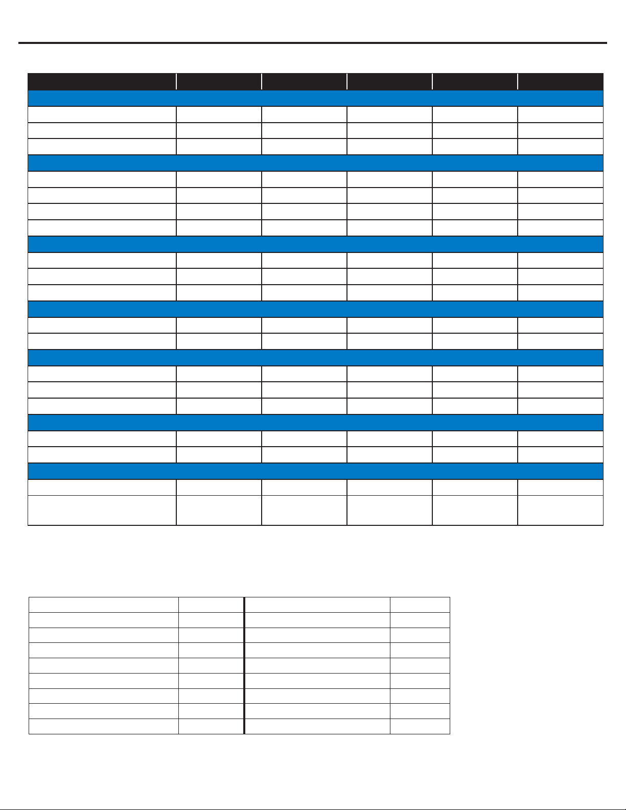
Turbidity < 1.0 net turbidity (NTU)
Conditions for Operation of TFC - Thin Film Composite Membrane
Used in the CommPro-Series
Source Water Supply - TFC Chemical Parameters - TFC
Community / Private Bacteriologically Safe Hardness (CaCo3)< 1 GPG
45 / 85 psiSystem Pressure min/max Iron (Fe) < 0.1 mg/L
Temperature 40º / 85º F Manganese (Mn) < 0.05 mg/L
pH Range 3.0 to 11.0 Hydrogen Sulde (H2S) 0.00 mg/L
Maximum supply TDS level 2000 mg/L Operating Limits
Maximum Pressure 150 PSI
(16)
Water Industries warrants its CommPro-Series Reverse Osmosis system to be free from
defects in materials and workmanship under normal use within the operating parameters
listed below. For a period of one year from the date of purchase, Water Industries will
repair or replace any part of the Reverse Osmosis System except the filters, membrane,
or battery.
Conditions of Warranty
The above warranty shall not apply to any part of the CommPro Reverse Osmosis System
that is damaged because of neglect, misuse, alteration, accident, misapplication, physical
damage, fouling, and/or scaling of the membrane by minerals, bacterial attack, sediment
or damage caused by fire, freezing, hot water, or an Act of God.
CommPro assumes no warranty liability in connection with this Reverse Osmosis System
other than as specified herein. Water Industries shall not be liable for consequential dam-
ages due to the use of CommPro products.
Warranty Service
Warranty service will be provided CommPro under the following conditions:
1. Contact your local Water Industries dealer, who will obtain return authorization instruc-
tions from CommPro.
2. Ship the unit or part freight prepaid to Water Industries Warehouse for warranty eval-
uation or service. The unit must be returned in the original carton or packaged to
prevent possible damage. Systems or parts covered under warranty shall be repaired
(or, at our option, replaced) and returned without charge.
This manual suits for next models
5
Table of contents
Other HM Digital Measuring Instrument manuals

HM Digital
HM Digital HydroMaster HM-500 User manual

HM Digital
HM Digital COM-300 User manual

HM Digital
HM Digital DM-1 User manual

HM Digital
HM Digital TDS-3 User manual

HM Digital
HM Digital COM-100 User manual

HM Digital
HM Digital COM-100 User manual

HM Digital
HM Digital PH-200 User manual

HM Digital
HM Digital FLM-3 User manual