HME VisionTech 2000 User manual

VisionTech™
2000
Version 9.0
Remote Video Transmission
and
Digital Recording System
Operating Instructions
HME# 400487
Rev B 10/29/02

VisionTechTM 2000
Version 9.0
HM Electronics, Inc.
14110 Stowe Drive
Poway, CA 92064
Sales: (858) 535-6060
Service: (858) 535-6030
Fax: (858) 552-0172
Copyright © October 2002, HM Electronics, Inc.
All Rights Reserved
TRADEMARK INFORMATION
HME, VisionTech and MegaMotion are registered trademarks of HM Electronics, Inc.
MS-DOS, Windows and Windows98 are registered trademarks of Microsoft Corporation.
Download.com is a trademark of CNET Networks, Inc.
All other trademarks are the property of their respective owners.
PRECAUTION ON COPYRIGHT
HME’s MegaMotion®board is not made or sold for unauthorized copying or
recording of copyrighted video works, including, without limitation, unauthorized
video recording from prerecorded copyrighted video products. Television
programs, films, videotapes and other materials might be copyrighted. Therefore,
unauthorized recording of such materials might be a violation of copyright law.

FCC NOTICE
This equipment has been tested and found to comply with the limits for a
Class A digital device, pursuant to Part 15 of the FCC Rules. Operation is
subject to the following two conditions: (1) this device may not cause
harmful interference and (2) this device must accept any interference
received, including interference that may cause undesired operation. These
limits are designed to provide reasonable protection against harmful
interference in residential installations. This equipment generates, uses, and
can radiate radio frequency energy and if not installed and used in
accordance with the instructions, might cause harmful interference to radio
communications. However, there is no guarantee that interference will not
occur in a particular installation.
If this equipment does not cause harmful interference to radio or television
reception, which can be determined by turning the equipment off and on,
the user is encouraged to try to correct the interference by one or more of
the following measures:
•Reorient or relocate the receiving antenna.
•Move the equipment away from the receiver.
•Plug the equipment into an outlet and circuit different from what
powers the receiver.
•If necessary, the user should consult the dealer or an e2000d
radio/television technician for additional suggestions.
Finally, any changes or modifications to the equipment by the user not
expressly approved by the grantee or manufacturer could void the user’s
authority to operate such equipment.

Minimum System Requirements For Upgrade Kits
•PENTIUM \CELERON CPU 500MHZ OR FASTER
•128 MB RAM
•1024 X 768 16-BIT VGA SCREEN DISPLAY
•WINDOWS 98 SE ONLY

MODULAR DESIGN
VisionTech 2000 Transmitter is available with many different features and capabilities.
The differences are intended to suit particular applications and customer needs. Most of the
differences depend on the software modules that have been installed on the transmitter.
This manual covers a VisionTech 2000 Transmitter system with all of its modules
enabled. If there is feature in this document that you are interested in, the features are listed in
the VisionTech program group, you can access the relevant part number in the Start Menu under
VisionTech\HME Modules Registration. If a module has been enabled on your system, it will be
listed as “Active”. If not, it will have a part number. Contact your dealer or vendor for pricing
and availability. Not all of the features listed will be available at the time of this publication.
With a full-featured version you can:
•Automatically accept a call from a PC running VisionTech 2000 Receiver Software
and transmit digital video over a Modem-to-Modem, LAN, WAN or Direct Cable
Connection.
•Control the camera views. View Touring allows you to automatically switch through
groups of cameras for hands free monitoring.
•Control Pan Tilt Zoom cameras.
•Respond to alarm triggers and trigger outputs to open doors or gates, turn on and off
lights and more.
•Automatically call a PC when an alarm trips and display a picture on its desktop of
what happened.
•Accept connections from as many as 255 receivers simultaneously.
•Record only when the video image has changed with HME’s hardware-based Video
Motion Detection.
•Record cameras regardless of what is on the screen. Previous VisionTech titles could
only record what was on the screen.
•Record video to a remote location or locally with Record On Demand.

TABLE OF CONTENTS
1. ACCESS RIGHTS ........................................................................................1
2. GENERAL ....................................................................................................4
3. COMMUNICATION....................................................................................5
4. LOCAL SITE.............................................................................................. 15
5. REMOTE SITES ........................................................................................17
6. CAMERA.................................................................................................... 19
7. AUDIO RECORD.......................................................................................23
8. PTZ..............................................................................................................28
9. EVENTS ......................................................................................................30
10. CASH REGISTER...................................................................................... 35
11. VIDEO MOTION DETECTION ...............................................................42
12. VIDEO MULTI-VIEW............................................................................... 45
13. ALARM I/O ................................................................................................47
14. NOTIFY ......................................................................................................51
15. RECORD ON DEMAND............................................................................57
16. CONTINUOUS RECORDING ..................................................................60
17. LOGICAL DIAGRAM ...............................................................................70
18. UTILITIES..................................................................................................77

VisionTech 2000 9.0 Setup Guide Access Rights
1
1. ACCESS RIGHTS
The Access Rights module protects the system setup configuration. Users will not be
able to enter areas of setup that may cause configuration errors and bring the system down.
Since exiting the program stops recording, operators can be denied exit rights.
Groups and Users
Entries made to Access Rights are sorted by Groups and Users. There can be up to 256
group entries and 256 users within each group. Access rights are granted or denied to each
group. Each user then shares the same rights within the group they belong to.
General VisionTech 2000 9.0 Setup Guide
2
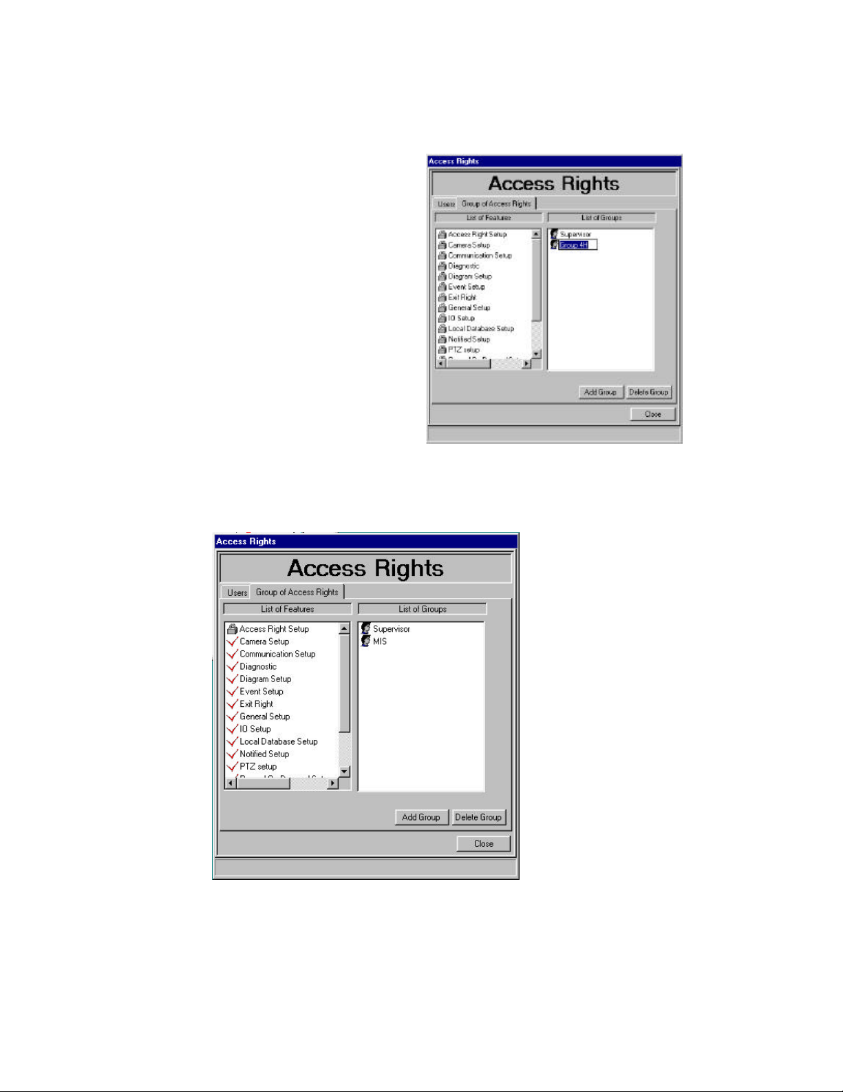
Adding Groups
The system has one default group entry
and one default user entry. The Supervisor
group has access to all levels. The default
group should not be removed since doing so
would lockout all users from the system. The
default user can be edited to fit the profile of
the environment it is placed in. To add a
group, click the Group of Access Rights tab on
the Access Rights dialog. Click on the Add
Group button. Once the entry is in place, the
name field is selected to accept the name of the
newly added group. All of the Assigned
Rights are locked as indicated by the padlock
icon next to the feature name.
Click the padlock icon next to the features you want to enable for this group. The icon
will change to a check mark.
All of the entries under List of
Features pertain to entering
VisionTech 2000 Setup except
for Exit Right.
VisionTech 2000 9.0 Setup Guide Access Rights
3
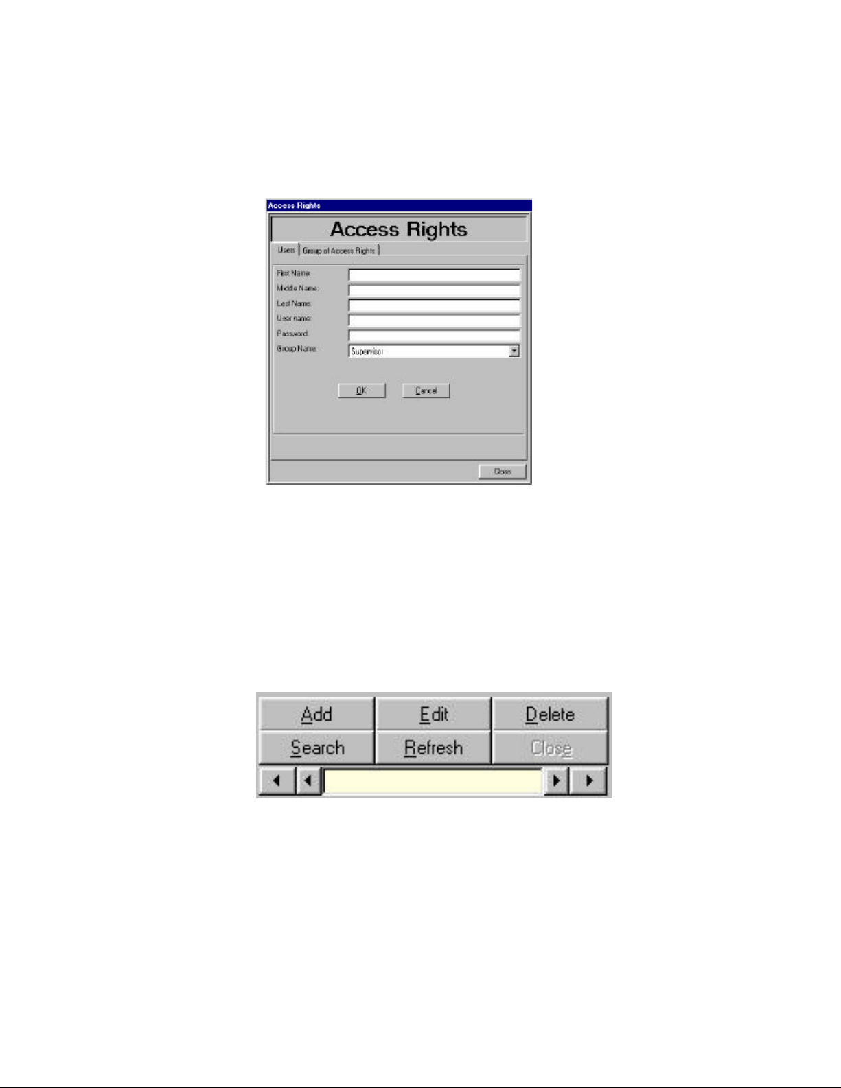
Adding Users
To add a user, click the Add button on the Users tab. The user information fields are then
enabled for input.
The Group Name drop down list will reflect entries made to the List of Groups. Select
the group this user will belong to. Note that a user can only belong to one group.
Managing Users
There are several buttons that provide additional tools to manage user accounts. Add
Edit and Delete are used to manage specific user information. Search and Refresh assist in
selecting the user record.
Once Search is clicked the user data fields become blank so you can enter search
criteria. Any part of the user’s record can be used to search. The inner arrows are used to
move to the next record (right arrow) or the previous record (left arrow). The outer arrows
will go to the last record (right arrow) or the first record (left arrow). Click Refresh if any
changes you have made are not updated on the screen
General VisionTech 2000 9.0 Setup Guide
4
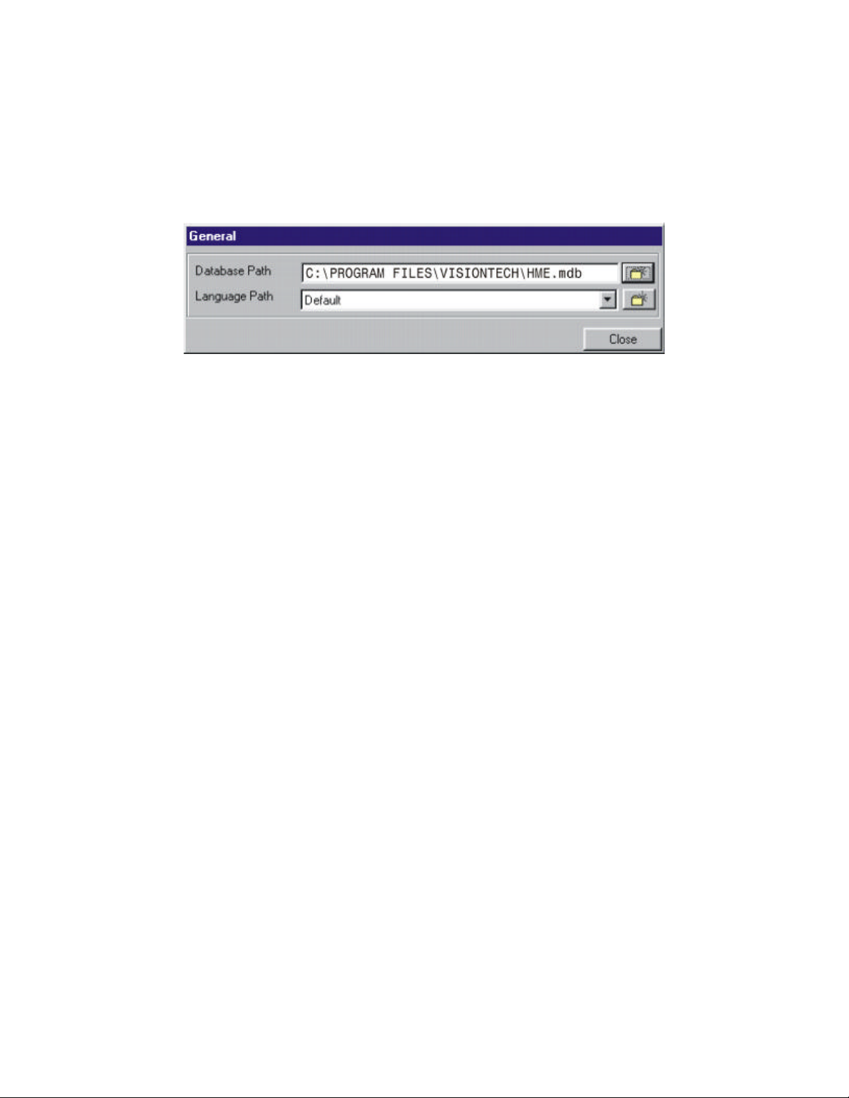
2. GENERAL
The General dialog shows the path of the VisionTech 2000 database. This database
contains all of the transmitter’s configuration information. It is not absolutely necessary for
changes to be made here although; the path may need to be changed to conform to other
languages.
The Language Path contains a file that is specific to each language that is supported by
VisionTech and Windows.
If the Wizard has taken you to General, simply click Next unless you are using a version
of Windows other than English.
Table of contents
Other HME Recording Equipment manuals


