HME TI6000 Manual

TI6000
Telephone Interface
INSTALLATION / OPERATING INSTRUCTIONS
The TI6000 provides a link between a telephone and the Wireless IQ System. It allows its user
to answer and speak on the telephone using a COM6000 COMMUNICATOR . The TI6000 can
only be used with Wireless IQ Systems that were originally configured for single-lane operation.
Figure 1. TI6000 with cables and telephone jack splitter
1. INSTALLATION
Installation of the TI6000 will take approximately 1 hour. Before you begin,
coordinate the time of installation with the store owner/manager to minimize
disruption of business.
The following tools are required: Phillips (cross-point) screwdriver, size #2
Power drill and drill bit set
Wire cutter/stripper
Small standard (slotted) screwdriver
1.1 Wall Mounting
The TI6000 must be mounted on the wall, not more than 2 ft (.61 meter) from the
Wireless IQ Base Station, so the base station interface cable will reach between the
two units. Mount the TI6000 as follows:
Hold the TI6000 against the wall at
the desired location. Mark the wall
through the screw hole in the flange
on each side of the unit.
Set the unit aside and drill two
3/16 inch (4.8 mm) holes at the
marked spots, deep enough to insert
the enclosed screw anchors.
Insert the screw anchors completely
into the two holes in the wall.
Hold the unit against the wall with
the holes in its flanges over the
anchors. Screw the two enclosed
screws through the holes, all the way
into the anchors.
Figure 2. Mark wall through screw holes
shown by arrows

2
1.2 Cable Connections and DIP Switch Settings
Connect the base station interface cable and telephone interface cable enclosed with the
TI6000 as shown in Figure 3 and described in the following paragraphs. Refer also to
the TI6000 wiring diagram, Figure 6.
Figure 3. TI6000 interfaces with base station and telephone
1.2.1 Telephone Interface Cable
The telephone interface cable is a 100 ft (30.48 meter) cable with a standard RJ11
telephone jack plug at each end.
Plug one end of the telephone interface cable into the receptacle on the TI6000,
as shown in Figure 4.
Unplug the telephone from its phone jack and plug the enclosed telephone jack
splitter into the phone jack. Plug the telephone and the TI6000 telephone
interface cable both into the telephone jack splitter.
Figure 4. TI6000 cable connections
Telephone
interface cable
Base station
interface cable
Figure 5. Telephone jack splitter

3
1.2.2 Base Station Interface Cable
There are two types of base station interface cables, as shown in Figure 6 below.
Follow the instructions that apply to the type of cable you received with the TI6000.
Figure 6. Two types of base station interface cables
Type 1 base station interface cable has a RJ45 connector at each end.
Type 2 base station interface cable has a RJ45 connector at one end, and five
connectors at the other end.
1. Type 1 Interface Cable Installation
This cable is used with Wireless IQ base stations that have a J33, RJ45 connector
and a S15 DIP switch on their circuit board.
Unplug the base station power
adapter from its electrical outlet.
Unscrew and remove the remote
antenna cable from the base
station.
Open the Wireless IQ Base
Station by pressing down on the
two release tabs on top of the
cabinet and carefully pulling its
front panel forward and down.
CAUTION: Open the front panel of
the base station carefully. Do not
let it drop.
Guide one end of the base station
interface cable through the hole
in the base station rear panel,
behind the unit and out the side
toward the TI6000.
At the end of the cable remaining
in the base station, plug the RJ45
connector into J33 on the base
station circuit board as shown
in the wiring diagram, Figure 7.
Plug the RJ45 connector at the
other end of the cable into the
TI6000 as shown in Figure 4.
NOTE: In this configuration, the
S15 DIP switch must have all
settings in the ON position.
See S15 DIP Switch Settings,
on page 5.
Figure 7. TI6000 wiring diagram if using the
Type 1 base station interface cable

4
2. Type 2 Interface Cable Installation
This cable is used with Wireless IQ base stations that do not have a J33, RJ45
connector on their circuit board, as seen in Figure 7.
Unplug the base station power adapter from its electrical outlet.
Unscrew and remove the remote antenna cable from the base station.
Open the Wireless IQ Base Station by pressing down on the two release tabs on
top of the cabinet and carefully pulling its front panel forward and down.
CAUTION: Open the front panel of the base station carefully. Do not let it drop.
Guide the RJ45 end of the cable through the hole in its rear panel, behind the
base station and out the side toward the TI6000.
Plug the five connectors into J9, J22, J25, J26 and J30 on the base station circuit
board as shown in the wiring diagram, Figure 8. Note the labels on the connector
wires. Each connector is keyed to fit into its correct position.
Plug the RJ45 connector at the other end of the base station interface cable into
the TI6000 as shown in Figure 4.
Figure 8. TI6000 wiring diagram if using the Type 2 base station interface cable

5
1.2.3 Switch Settings
1. K1 DIP Switch:
Locate the K1 DIP switch on the
Transceiver Circuit Board in the
Wireless IQ Base Station,
shown in Figure 9.
Set the K1 DIP switch to
the following positions:
1 –ON
2 –ON
3 –OFF
4 –OFF
Press the RESET button.
Close the base station and reconnect the remote antenna cable to it.
NOTE: If you are going to set the ceiling speaker to beep when the phone rings,
wait to close the base station until you have finished #2 below.
2. Optional Ceiling Speaker Ring Setting:
Ask the store owner/manager if
they want to hear a single beep
through the ceiling speaker when
the phone rings. If so, locate the
S6 DIP switch shown in Figure 10,
at the lower-right corner of the
audio circuit board in the base
station.
Set S6, 6 to the ON position.
Close the base station and reconnect
the remote antenna
cable to it.
3. S15 DIP Switch
NOTE: You will only have the
S15 DIP switch if you received the
TYPE 1 base station interface cable.
The S15 DIP switch on the Audio
Circuit Board in the Wireless IQ Base
Station must have all four positions
set to ON, as shown in Figure 11.
K1 DIP switch
Reset button
Figure 9. K1 DIP switch and reset button
S6, 6
Figure 10. S6 DIP switch
Figure 11. S15 DIP switch
S15

6
RECORD
button
4. Optional Voice Message Prompt Setting:
The Wireless IQ System can be set up to give a voice message in the headset when
the phone is hung up (if either the Red message or Green message is not currently
in use). To record a voice message, refer to Figure 12 and follow the instructions
below.
Set the desired RED or GREEN MESSAGE switch on the base station to ON.
Press and release the RECORD button on the base station. The RECORD light on
the base station should be red for RED MESSAGE or green for GREEN MESSAGE.
Press and hold the “B” button on the COMMUNICATOR while recording a message
(example: “The phone is hung up.”)
Set the RED or GREEN MESSAGE CONTROL switches on the base station as follows:
1 –ON = Inbound during message
2 –ON = Message to headset
5 –ON = Trigger message from alert
NOTE: Setting 5 to OFF will replace the message with three beeps.
1.3 Equipment Checkout
Set the POWER and RINGER switches on the bottom of the TI6000, shown in
Figure 14, to the ON position.
Use your cell phone to call the store phone.
Have someone in the store, wearing a Communicator in the A2 mode, listen for the
call. When the phone rings in their headset, they should press and release the A2
button again to connect to the incoming call. Tell them to press and hold the B
button to talk and listen. When you are finished, have them press and hold A2 for
longer than two seconds to disconnect.
Talk and listen to the person with the Communicator to be sure they can hear you
and you can hear them at a comfortable level.
CAUTION: The following adjustments should only be made by the installer,
when the TI6000 is being installed.
If the ring tone level or incoming voice level
is not at an acceptable level, unscrew the
four screws on the front cover of the TI6000
with a Phillips (crosspoint) screwdriver and
adjust R10 for the ring level and/or R16 for
the voice level as needed. See Figure 13.
Call the store phone again to check out the
ring or voice level. Replace the cover on
the unit when you are satisfied with the
ring/voice level.
Figure 12. Indicator lights and switches on base station
Figure 13. R10 and R16 adjustments

7
2. OPERATION
The TI6000 allows you to answer incoming phone calls and talk on the telephone
using a COM6000 COMMUNICATOR . To do this, follow the instructions below.
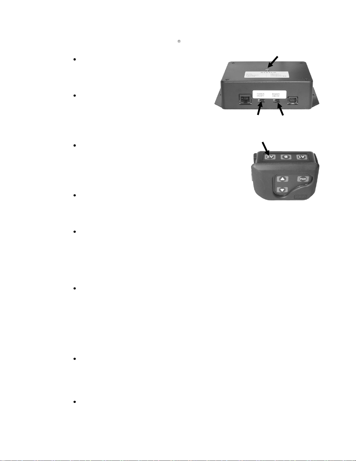
Power ON –Be sure the power switch on
the bottom of the TI6000 is in the ON
position. The status light on the TI6000
will be on steady red when the power is on
and there is no incoming telephone call.
Ringer ON/OFF –If the ringer switch on
the TI6000 is in the ON position and your
Communicator is in the A2 mode, you will
hear two ring tones in your headset for
incoming calls. If the ringer switch is in
the OFF position, you will not hear any
ring tones in your headset for incoming calls.
A2 mode –The Communicator must be in the A2 mode
to hear the ring tones in the headset. When there is no
incoming telephone call press and release the A2 button
on the Communicator to be sure it is in the A2 mode. Be
sure the status light is red. If not, press and hold the A2
button again until you hear three beeps in the headset
and the status light changes to red.
Incoming Phone call –If the TI6000 ringer switch is in
the ON position, you will hear two ring tones in your
headset, and the status light on the TI6000 will alternate
flashing green and red. If the ringer switch is in the OFF
position, you will only hear the ringing from the telephone itself.
Answering the Phone –To answer the phone, press and release the A2 button on
your Communicator. A single beep in your headset will indicate the phone is off the
hook. The status light on the TI6000 will turn green when the phone is answered,
and remain on steady green while the phone call is active. Press and hold the B
button while talking to the person on the phone.
NOTE: If you move out of range of the antenna during a phone conversation, you
will hear “Out of range” in your headset. When you re-enter the antenna range,
you will hear “Lane 1 (or 2) ready,” but you will remain connected to the caller.
Hanging up the Phone –To hang up the phone, press and hold the A2 button for
longer than 2 seconds. (If you are using your Communicator in the Hands-Free
mode, the A2 button does not have to be held for 2 seconds. Just press and
release it.) Three beeps in your headset will indicate the phone is hung up. The
status light on the TI6000 will turn red when the phone line has been hung up. If
the phone is not hung up, the TI6000 will automatically hang up the phone after 5
minutes if neither A2 nor B button has been pushed since the call ended.
NOTE: If the optional voice message prompt was set up (See section 1.2.3), a
recorded voice message will be heard in the headset instead of three beeps when
the phone is hung up.
Privacy –The privacy function allows you to talk privately on the phone without
the other Communicator users hearing your conversation. If the phone is
answered with the Communicator, picking up the office phone and leaving it off
the hook during the conversation will prevent other Communicator users from
hearing. Also, Communicator users will not be able to hear the conversation if the
office phone is used to pick up the call first.
Ceiling speaker ring option –If the optional ceiling speaker ring was set up
(See section 1.2.3), one beep will be heard in the ceiling speaker the first time the
phone rings.
Status light
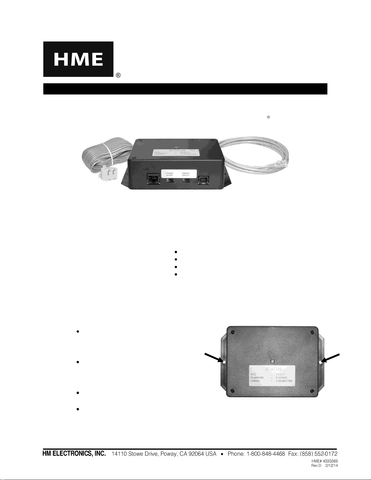
Figure 14. POWER and RINGER switches
Figure 15. A2 button

8
3. IN CASE OF PROBLEMS
Problem
Probable Cause
Solution
No rings heard in headset
Ringer switch not on.
Set Ringer switch to ON position.
In A1 mode instead of A2.
Switch to A2 mode.
STATUS light on TI6000
not lit.
Power not on.
Set power switch to ON position.
Base station interface cable not plugged
in to TI6000.
Plug in cable to TI6000.
Power wire disconnected from connector
in base station.
Call HME.*
Talking heard in only one
direction.
Interface cable wires not correctly
attached to connectors in base station.
Call HME.*
Ring tone low.
Ring tone level not adjusted correctly.
Call HME.*
Caller’s voice level low.
Level not adjusted correctly.
Call HME.*
Caller can’t hear you talk.
Not pushing Communicator button B to
talk to person on phone.
Press and hold the B button while talking
on the phone.
TI6000 not operating
correctly.
K1 switches not set properly on base
station transceiver circuit board.
On base station transceiver circuit board,
set K1-1 and K1-2 switches to ON. Press
RESET button. See Figure 9.
Wiring incorrect.
Call HME.*
* For assistance call HME Technical Support at 1-800-848-4468 or Fax 858-552-0172.
IMPORTANT!
Waste Electrical and Electronic Equipment (WEEE)
The European Union (EU) WEEE Directive (2002/96/EC) places an obligation on producers
(manufacturers, distributors and/or retailers) to take-back electronic products at the end of their
useful life. The WEEE Directive covers most HME products being sold into the EU as of August
13, 2005. Manufacturers, distributors and retailers are obliged to finance the costs of recovery
from municipal collection points, reuse, and recycling of specified percentages per the WEEE
requirements.
Instructions for Disposal of WEEE by Users in the European Union
The symbol shown below is on the product or on its packaging which indicates that this product was
put on the market after August 13, 2005 and must not be disposed of with other waste. Instead, it is
the user’s responsibility to dispose of the user’s waste equipment by handing it over to a designated
collection point for the recycling of WEEE. The separate collection and recycling of waste equipment
at the time of disposal will help to conserve natural resources and ensure that it is recycled in a
manner that protects human health and the environment. For more information about where you
can drop off your waste equipment for recycling, please contact your local authority, your household
waste disposal service or the seller from whom you purchased the product.

“HME Proprietary and Confidential Information not to be duplicated, disclosed or
distributed except as permitted by an executed Confidentiality and Non-Disclosure
Agreement with HME. Copyright HM Electronics, Inc. 2014”
Table of contents
Other HME Recording Equipment manuals