HMS Networks Anybus Wireless Bolt IoT AWB1000 User manual

Anybus®Wireless Bolt IoT™
USER MANUAL
SCM-1202-139 1.0 en-US ENGLISH

Important User Information
Disclaimer
The information in this document is for informational purposes only. Please inform HMS Industrial Networks of any
inaccuracies or omissions found in this document. HMS Industrial Networks disclaims any responsibility or liability
for any errors that may appear in this document.
HMS Industrial Networks reserves the right to modify its products in line with its policy of continuous product
development. The information in this document shall therefore not be construed as a commitment on the part of
HMS Industrial Networks and is subject to change without notice. HMS Industrial Networks makes no commitment
to update or keep current the information in this document.
The data, examples and illustrations found in this document are included for illustrative purposes and are only
intended to help improve understanding of the functionality and handling of the product. In view of the wide range
of possible applications of the product, and because of the many variables and requirements associated with any
particular implementation, HMS Industrial Networks cannot assume responsibility or liability for actual use based on
the data, examples or illustrations included in this document nor for any damages incurred during installation of the
product. Those responsible for the use of the product must acquire sufficient knowledge in order to ensure that the
product is used correctly in their specific application and that the application meets all performance and safety
requirements including any applicable laws, regulations, codes and standards. Further, HMS Industrial Networks will
under no circumstances assume liability or responsibility for any problems that may arise as a result from the use of
undocumented features or functional side effects found outside the documented scope of the product. The effects
caused by any direct or indirect use of such aspects of the product are undefined and may include e.g. compatibility
issues and stability issues.
Anybus®Wireless Bolt IoT™User Manual SCM-1202-139 1.0 en-US

Anybus®Wireless Bolt IoT™User Manual SCM-1202-139 1.0 en-US
Table of Contents Page
1 Preface ................................................................................................................................ 3
1.1 About This Document .......................................................................................................3
1.2 Document Conventions.....................................................................................................4
1.3 Trademarks.....................................................................................................................4
2 Safety ................................................................................................................................... 5
2.1 General Safety Instructions................................................................................................5
2.2 Intended Use...................................................................................................................5
3 Preparation.......................................................................................................................... 6
3.1 Support and Downloads ....................................................................................................6
3.2 Network Environment.......................................................................................................6
3.3 SIM Card ........................................................................................................................6
3.4 Placement ......................................................................................................................6
3.5 Firewall and Routing.........................................................................................................6
4 Installation........................................................................................................................... 7
4.1 Installing SIM Card ...........................................................................................................7
4.2 Mechanical Installation .....................................................................................................8
4.3 Connecting to Ethernet/Power Over Ethernet (PoE) ...............................................................9
4.4 Connecting to Power ...................................................................................................... 10
5 Configuration..................................................................................................................... 12
5.1 Connecting to PC and Power............................................................................................ 12
5.2 PC IP Address Setting...................................................................................................... 13
5.3 Accessing Wireless Bolt IoT Web Interface.......................................................................... 14
5.4 Web Interface Overview.................................................................................................. 15
5.5 Save and Reboot............................................................................................................ 15
5.6 Factory Default Settings .................................................................................................. 16
5.7 Ethernet Settings ........................................................................................................... 17
5.8 Cellular Settings............................................................................................................. 19
6 Configuration Examples .................................................................................................... 23
6.1 Setting Up Wireless Bolt IoT as an Internet Router ............................................................... 23
6.2 Setting Up Wireless Bolt IoT with ULPM ............................................................................. 25
6.3 Setting Up Wireless Bolt IoT with REST Commands .............................................................. 26
7 Verify Operation................................................................................................................ 27
7.1 System Settings and Network Connection........................................................................... 27
7.2 Ethernet LED Status Indication ......................................................................................... 28

Anybus®Wireless Bolt IoT™User Manual SCM-1202-139 1.0 en-US
8 Maintenance...................................................................................................................... 29
8.1 Firmware Update ........................................................................................................... 29
8.2 Set Administrator Password ............................................................................................. 30
8.3 Settings Backup ............................................................................................................. 31
8.4 Reboot System .............................................................................................................. 32
9 Troubleshooting ................................................................................................................ 33
9.1 Logs............................................................................................................................. 33
9.2 Diagnostics ................................................................................................................... 34
9.3 Reset and Recovery........................................................................................................ 37
10 Technical Data ................................................................................................................... 39
10.1 Technical Specifications................................................................................................... 39

Preface 3 (40)
1 Preface
1.1 About This Document
This manual describes how to install and configure Anybus Wireless Bolt IoT.
For additional documentation and software downloads, FAQs, troubleshooting guides and
technical support, please visit www.anybus.com/support.
Anybus®Wireless Bolt IoT™User Manual SCM-1202-139 1.0 en-US
Preface 4 (40)
1.2 Document Conventions
Numbered lists indicate tasks that should be carried out in sequence:
1. First do this
2. Then do this
Bulleted lists are used for:
• Tasks that can be carried out in any order
• Itemized information
►An action
→ and a result
User interaction elements (buttons etc.) are indicated with bold text.
Program code and script examples
Cross-reference within this document: Document Conventions, p. 4
External link (URL): www.hms-networks.com
WARNING
Instruction that must be followed to avoid a risk of death or serious injury.
Caution
Instruction that must be followed to avoid a risk of personal injury.
Instruction that must be followed to avoid a risk of reduced functionality and/or damage
to the equipment, or to avoid a network security risk.
Additional information which may facilitate installation and/or operation.
1.3 Trademarks
Anybus®is a registered trademark of HMS Industrial Networks. All other trademarks mentioned
in this document are the property of their respective holders.
Anybus®Wireless Bolt IoT™User Manual SCM-1202-139 1.0 en-US
Safety 5 (40)
2 Safety
2.1 General Safety Instructions
Caution
This equipment emits RF energy in the ISM (Industrial, Scientific, Medical) band. Make
sure that all medical devices used in proximity to this equipment meet appropriate
susceptibility specifications for this type of RF energy.
This equipment is recommended for use in both industrial and domestic environments.
For industrial environments it is mandatory to use the functional earth connection to
comply with immunity requirements. For domestic environments the functional earth
must be used if a shielded Ethernet cable is used, in order to meet emission requirements.
This equipment contains parts that can be damaged by electrostatic discharge (ESD). Use
ESD prevention measures to avoid damage.
2.2 Intended Use
The intended use of this equipment is as a communication interface and router. The equipment
receives and transmits data over Ethernet and Cellular standard networks.
Anybus®Wireless Bolt IoT™User Manual SCM-1202-139 1.0 en-US

Preparation 6 (40)
3 Preparation
3.1 Support and Downloads
For additional documentation and software downloads, FAQs, troubleshooting guides and
technical support, please visit www.anybus.com/support.
Have the product article number available, to search for the specific product page.
You find the product article number on the product cover.
3.2 Network Environment
Ensure that you have all the necessary information about the capabilities and restrictions of your
local network environment before installation.
Ensure that the network operator supports your intended network type(s), Cat-M1,NB-IoT or
GSM GPRS/EDGE, at the location where Wireless Bolt IoT is to be installed.
3.3 SIM Card
Network Type Considerations
Order a SIM card that supports the network type(s), Cat-M1,NB-IoT or GSM GPRS/EDGE.
Prepaid Data Plan
If a prepaid data plan is used, ensure that:
• the data amount is sufficient
• that any SMS notifications are sent to a monitored number
3.4 Placement
For optimal reception, cellular devices should not be confined in buildings made of concrete or
metal, without windows.
To avoid interference, a minimum distance of 50 cm between cellular devices should be
observed.
At least 20 cm separation distance between the device and the user’s body must be maintained
at all times.
3.5 Firewall and Routing
There are routing options set for the system.
The firewall allow routing of:
• Outgoing traffic for TCP, UDP and ICMP (for ipv4 only).
• Ingoing traffic for already established connections only.
Anybus®Wireless Bolt IoT™User Manual SCM-1202-139 1.0 en-US
Installation 7 (40)
4 Installation
4.1 Installing SIM Card
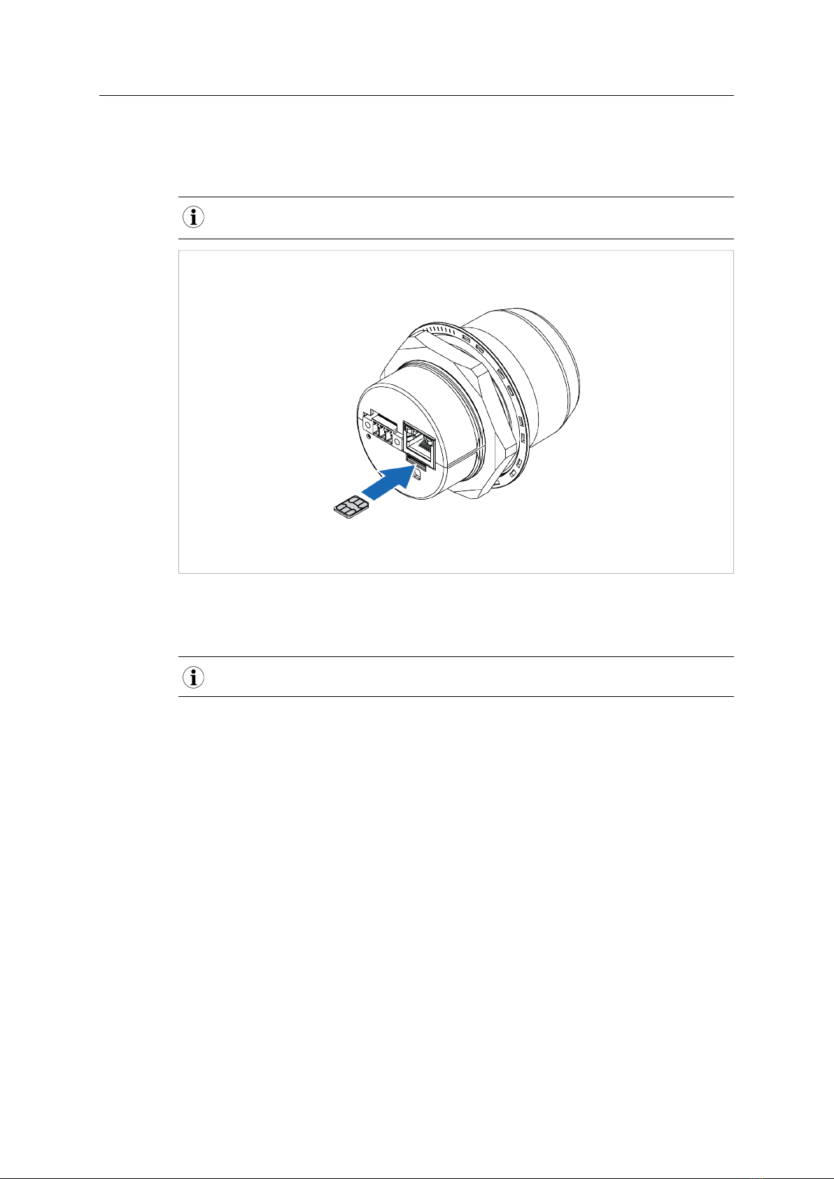
Supported SIM card types are Nano SIM for IoT and M2M, for data communication, as well as standard
mobile phone Nano SIM.
Fig. 1
To connect Wireless Bolt IoT to a cellular data network, install a cellular SIM card:
1. Insert a SIM card into the Wireless Bolt IoT SIM card holder.
Ensure that the SIM card contact surface is facing towards the Ethernet port.
Anybus®Wireless Bolt IoT™User Manual SCM-1202-139 1.0 en-US

Installation 8 (40)
4.2 Mechanical Installation
Placement
• The device is intended to be mounted on top of a machine or cabinet through an M50
(50.5 mm) hole using the included sealing ring and nut.
• The top mounting surface, in contact with the sealing, must be flat with a finish equivalent
to Ra 3.2 or finer and cleaned and free from oils and greases.
• For optimal reception, cellular devices require a zone around them clear of objects that
could obstruct or reflect the signal. To avoid interference, a minimum distance of 50 cm
between Wireless Bolt IoT and other cellular devices should be observed.
Make sure that the sealing ring is correctly placed in the circular groove in the top part of
the housing before tightening the nut.
Always hold the BOTTOM part of the unit when untightening the nut, not the top part
(the cap).
Tightening torque: 5 Nm ±10 %
Fig. 2 Installation drawing
All measurements are in mm.
Anybus®Wireless Bolt IoT™User Manual SCM-1202-139 1.0 en-US

Installation 9 (40)
4.3 Connecting to Ethernet/Power Over Ethernet (PoE)
Before You Begin
Shielded or unshielded Ethernet cables may be used.
Wireless Bolt IoT is designed to comply with PoE class 0 (37-57 VDC, max 0.35 A), according to IEEE
802.3.
Procedure
Fig. 3
1. Connect the Wireless Bolt IoT Ethernet port to Ethernet/PoE.
Ethernet Connector, RJ45 PoE
Pin Data PoE
1 TD+ A+ Positive power from alt. A PSE
2 TD-
3 RD+ A- Negative power from alt. A PSE (with pin 6)
4B+ Positive power from alt. B PSE
5
6 RD- A- Negative power from alt. A PSE (with pin 3)
7B- Negative power from alt. B PSE
8
Housing Shield Functional Earth (FE), via 1 nF capacitor and 1 MΩ bleeder resistor
2. Connect Wireless Bolt IoT to Functional Earth (FE) via the Power connector.
Follow the instruction in Connecting to Power, p. 10.
Anybus®Wireless Bolt IoT™User Manual SCM-1202-139 1.0 en-US
Installation 10 (40)
4.4 Connecting to Power
Before You Begin
Connecting power with reverse polarity or using the wrong type of power supply may
damage the equipment. Make sure that the power supply is connected correctly and of
the recommended type.
When Wireless Bolt IoT is powered via the power connector, Functional Earth (FE) must
be connected.
When Wireless Bolt IoT is installed in an environment with a high level of electrical noise, use a power/
Functional Earth (FE) cable with a maximum length of 3 meters.
See also Technical Data, p. 39 regarding power supply requirements.
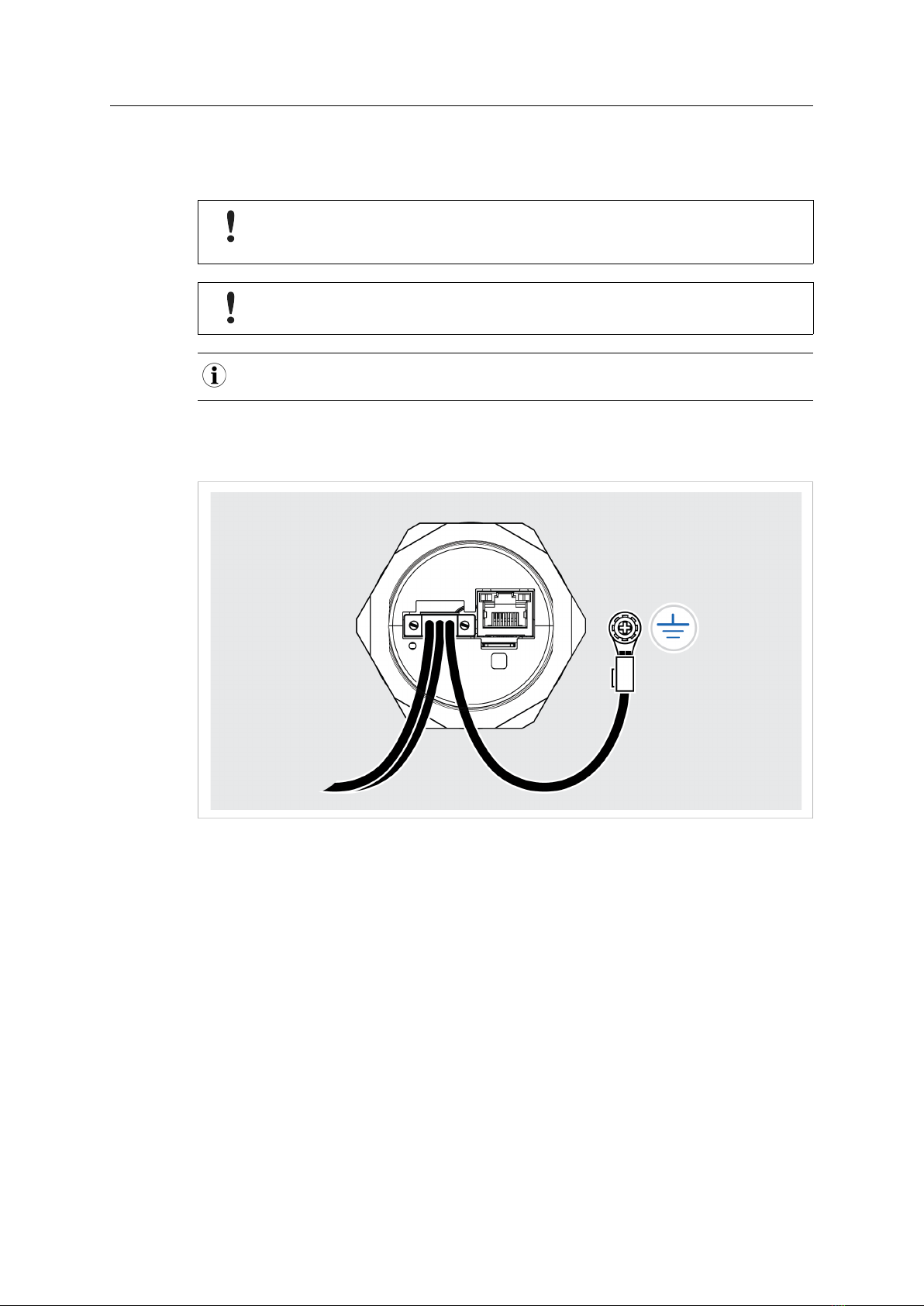
Functional earth wire screw placement
Fig. 4
When Wireless Bolt IoT is mounted on a sheet metal plate, connect Functional Earth (FE) to the
plate near Wireless Bolt IoT.
Anybus®Wireless Bolt IoT™User Manual SCM-1202-139 1.0 en-US

Installation 11 (40)
Procedure
Fig. 5
1. Connect Wireless Bolt IoT Power connector to a power supply.
2. Connect Wireless Bolt IoT Power connector to Functional Earth (FE).
Power connector, 3-pin terminal block
Pin Function
1+11–33 VDC
2-
3Functional Earth (FE)
Anybus®Wireless Bolt IoT™User Manual SCM-1202-139 1.0 en-US
Configuration 12 (40)
5 Configuration
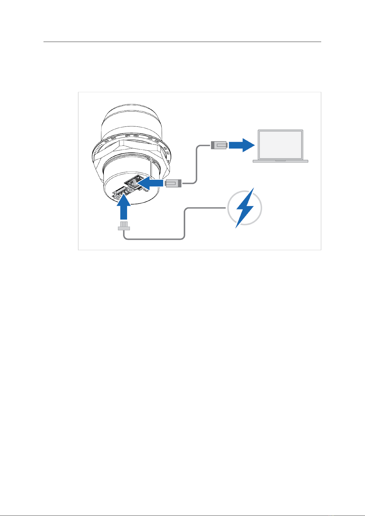
5.1 Connecting to PC and Power
When configuring Wireless Bolt IoT it must be connected to a PC.
Fig. 6
1. Connect the Wireless Bolt IoT Ethernet port to your PC.
2. Connect the Wireless Bolt IoT Power connector to a power supply.
Anybus®Wireless Bolt IoT™User Manual SCM-1202-139 1.0 en-US

Configuration 13 (40)
5.2 PC IP Address Setting
By default, Wireless Bolt IoT is set to use the internal DHCP server.
If there is already a DHCP server on the network, you must disable the internal DHCP
server.
Wireless Bolt IoT default IP address is 192.168.0.98.
To find Wireless Bolt IoT on your network:
Set a Static IP Address on Your PC
On the PC accessing the Wireless Bolt IoT built-in web interface:
1. Set a static IP address within the same IP address range as the Wireless Bolt IoT IP address.
Finding Wireless Bolt IoT with IPconfig
1. Download the HMS software application IPconfig installation files and user documentation
from www.anybus.com/support.
2. Install IPconfig on your PC.
3. In IPconfig, start a network scan to find the Wireless Bolt IoT IP address on your network.
4. Set an IP address on the Wireless Bolt IoT Ethernet port within the same IP address range as
your PC IP address.
Result
→ Now you can enter the Wireless Bolt IoT IP address in your web browser and search to
access the built-in web interface login page.
Refer to Accessing Wireless Bolt IoT Web Interface, p. 14
Anybus®Wireless Bolt IoT™User Manual SCM-1202-139 1.0 en-US
Configuration 14 (40)
5.3 Accessing Wireless Bolt IoT Web Interface
The Wireless Bolt IoT built-in web interface can be accessed from standard web browsers.
Before installing the Wireless Bolt IoT on a network, change the Wireless Bolt IoT default
administrator password.
The Wireless Bolt IoT comes with a default administrator password.
You find the default administrator password on the Wireless Bolt IoT cover.
Wireless Bolt IoT default IP address is 192.168.0.98.
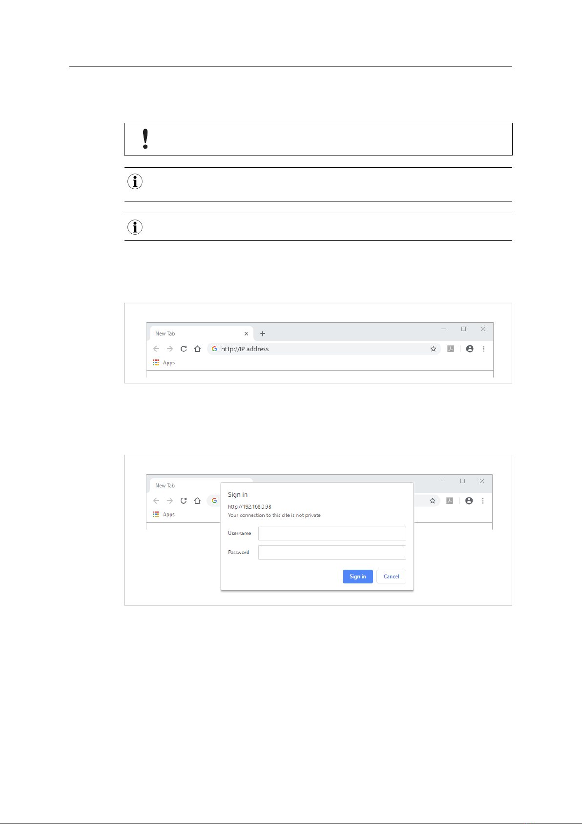
Login to the Wireless Bolt IoT built-in web interface:
1. Open a web browser.
2. Click to select the Address bar and enter the Wireless Bolt IoT IP address.
Fig. 7
3. Press Enter.
→ The built-in web interface login screen appears.
4. Enter Username and Password and click Sign in.
Fig. 8
Anybus®Wireless Bolt IoT™User Manual SCM-1202-139 1.0 en-US

Configuration 15 (40)
5.4 Web Interface Overview
The Wireless Bolt IoT built-in web interface is used to configure the Wireless Bolt IoT system
settings and to monitor xxx.
The System Overview page shows the current settings and network connection status.
Fig. 9 Example, Wireless Bolt IoT built-in web interface, example
A. System Overview
Shows the current settings and network connection status
B. Left sidebar menu
– System Overview
– Ethernet Settings
– Cellular Settings
– Firmware Update
– Logs
– System
C. Save and Reboot button and Cancel All Changes button
5.5 Save and Reboot
Cancel Changes
Fig. 10
If you need to cancel the changes you have made to the settings:
1. In the left sidebar menu, click Cancel All Changes.
To restore settings, refer to Restore Settings, p. 32.
Anybus®Wireless Bolt IoT™User Manual SCM-1202-139 1.0 en-US

Configuration 16 (40)
Apply Changes
Fig. 11
To apply changes:
1. In the left sidebar menu, click Save and Reboot.
→ Wireless Bolt IoT restarts for the changes to take effect.
5.6 Factory Default Settings
Wireless Bolt IoT comes with the following factory default settings.
Wireless Bolt IoT default settings
IP Assignment Static
IP Address 192.168.0.98
Subnet Mask 255.255.255.0
Default Gateway 192.168.0.98
Internal DHCP Server Enabled
Network Type Automatic
Connects automatically to an available network according
to priority order Cat-M1, NB-IoT and GPRS/EDGE/2G
mobile network.
You can restore factory default settings by making a Factory Reset. Refer to Factory Reset, p. 37
Anybus®Wireless Bolt IoT™User Manual SCM-1202-139 1.0 en-US
Configuration 17 (40)
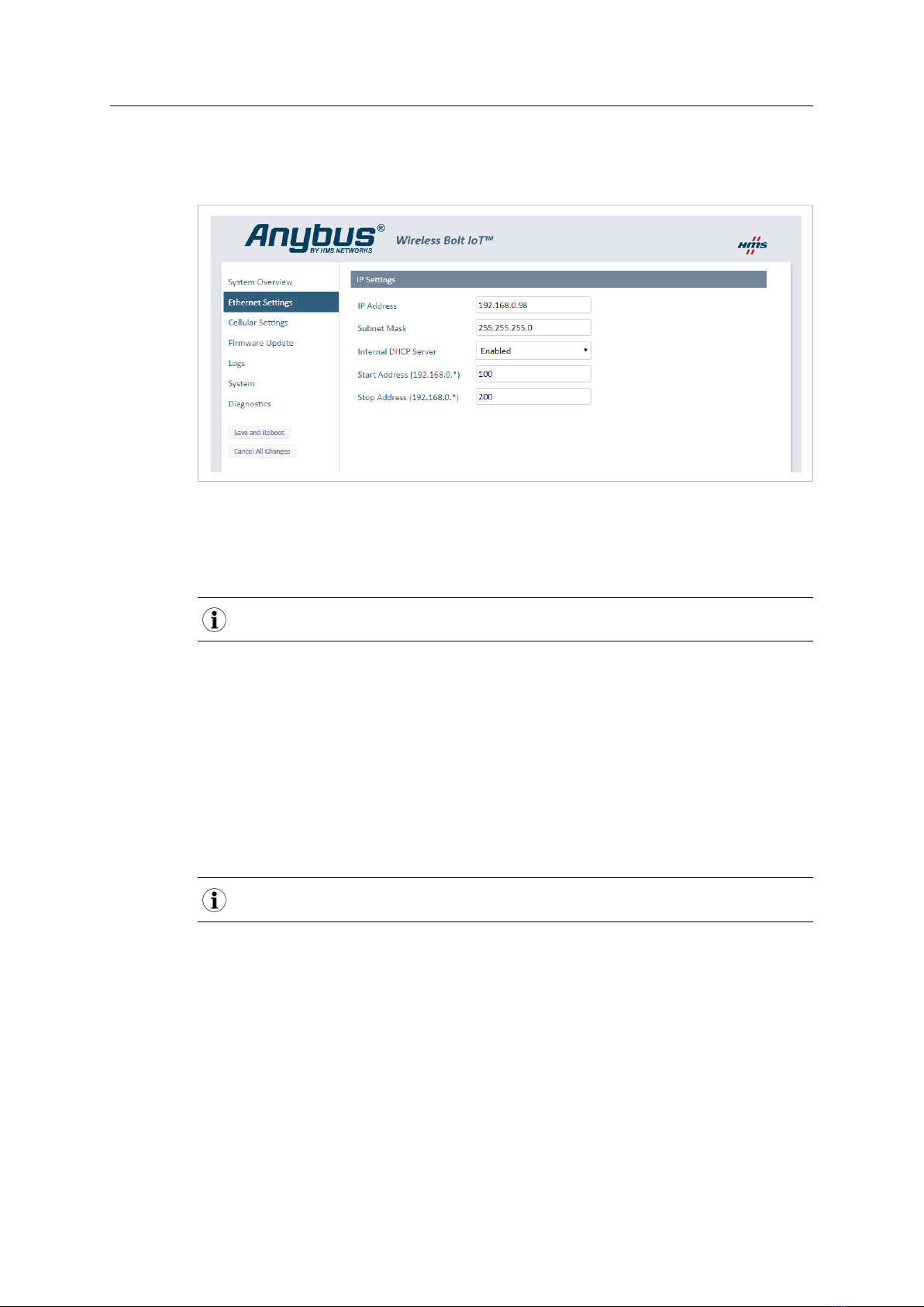
5.7 Ethernet Settings
On the Ethernet Settings page:
Fig. 12 Default, IP Settings with Internal DHCP Server Enabled
IP Settings
IP Address
The default Wireless Bolt IoT static IP address is 192.168.0.98.
When you change the IP address:
1. Click Save and Reboot to reboot Wireless Bolt IoT.
→ Wireless Bolt IoT reboots for the setting to take effect.
2. In your web browser, enter the new IP address an press Enter.
→ The built-in web interface login screen appears.
3. Enter Username and Password and click Sign in.
Subnet Mask
The default subnet mask is 255.255.255.0.
The subnet mask is used to identify the network address of the static IP address.
Anybus®Wireless Bolt IoT™User Manual SCM-1202-139 1.0 en-US

Configuration 18 (40)
Internal DHCP Server
If there is already a DHCP server on the network, you must set the Internal DHCP Server
setting to Disabled.
The DHCP server is only enabled on the LAN interface.
By default, Internal DHCP Server is set to Enabled.
→ This means that the IP address settings are set automatically by the Wireless Bolt IoT
internal DHCP server.
IP Address Range
When the Wireless Bolt IoT is enabled, you can still use static IP addresses within the remaining IP
address range. The devices assigned to these IP addresses can set Wireless Bolt IoT as the default
gateway and DNS server.
The internal DHCP server address host ID range is by default set to start at 100 and stop at 200.
You can set a preferred host ID range.
Anybus®Wireless Bolt IoT™User Manual SCM-1202-139 1.0 en-US
This manual suits for next models
1
Table of contents
Other HMS Networks Industrial Equipment manuals


