Hobart Creator Series User manual

OM-281996B
2018−06
www.HobartWelders.com
CreatortSeries
Auto-Darkening Welding Helmets

TABLE OF CONTENTS
SECTION 1 −WELDING HELMET SAFETY PRECAUTIONS −READ BEFORE USING 1......
1-1. Symbol Usage 1.............................................................
1-2. Arc Welding Hazards 1.......................................................
1-3. Proposition 65 Warnings 2....................................................
1-4. Lens Shade Selection Table 3.................................................
1-5. Principal Safety Standards 3..................................................
SECTION 2 −SPECIFICATIONS 4.....................................................
SECTION 3 −OPERATING INSTRUCTIONS 5..........................................
3-1. Helmet Controls 5...........................................................
3-2. Low Battery Indicator 5.......................................................
3-3. Lens Delay Control 6.........................................................
3-4. Variable Shade Control (No. 9–13) 6............................................
3-5. Sensitivity Control 7..........................................................
3-6. Weld/Grind Mode Switch 8....................................................
3-7. Power Modes 8.............................................................
SECTION 4 −ADJUSTING HEADGEAR 9..............................................
SECTION 5 −REPLACING THE LENS COVERS 10.....................................
5-1. Replacing Outside Lens Cover 10..............................................
5-2. Replacing Inside Lens Cover 11................................................
SECTION 6 −REPLACING THE BATTERY 12..........................................
SECTION 7 −INSTALLING OPTIONAL MAGNIFYING LENS 13..........................
SECTION 8 −MAINTENANCE 13.....................................................
SECTION 9 −TROUBLESHOOTING 14................................................
SECTION 10 −PARTS LIST 15.......................................................
SECTION 11 −LIMITED WARRANTY 16...............................................

OM-281996 Page 1
SECTION 1 −WELDING HELMET SAFETY PRECAUTIONS −
READ BEFORE USING
helmet 2018−04
Protect yourself and others from injury — read, follow, and save these important safety
precautions and operating instructions.
1-1. Symbol Usage
This group of symbols means Warning! Watch
Out! ELECTRIC SHOCK, MOVING PARTS,
and HOT PARTS hazards. Consult symbols
and related instructions below for necessary
actions to avoid the hazards.
Indicates special instructions.
DANGER! −Indicates a hazardous
situation which, if not avoided, will
result in death or serious injury. The
possible hazards are shown in the
adjoining symbols or explained in
the text.
Indicates a hazardous situation
which, if not avoided, could result in
death or serious injury. The possible
hazards are shown in the adjoining
symbols or explained in the text.
NOTICE −Indicates statements not related to
personal injury.
1-2. Arc Welding Hazards
Only qualified persons should install, operate, maintain, and repair this equipment. A
qualified person is defined as one who, by possession of a recognized degree, certificate,
or professional standing, or who by extensive knowledge, training and experience, has
successfullydemonstrated ability to solve or resolve problems relating to the subject
matter, the work, or the project and has received safety training to recognize and avoid
the hazards involved.
Arc rays from the welding process produce intense visible and invisible (ultravio-
let and infrared) rays that can burn eyes and skin. Sparks fly off from the weld.
Wear a welding helmet fitted with a proper shade of filter to protect your face and eyes when
welding or watching (see ANSI Z49.1 and Z87.1 listed in Safety Standards). Refer to Lens
Shade Selection table in Section 1-4.
Wear approved safety glasses with side shields under your helmet.
Use protective screens or barriers to protect others from flash, glare, and sparks; warn
others not to watch the arc.
Wear body protection made from durable, flame−resistant material (leather, heavy cotton,
wool). Body protection includes oil-free clothing such as leather gloves, heavy shirt, cuffless
trousers, high shoes, and a cap.
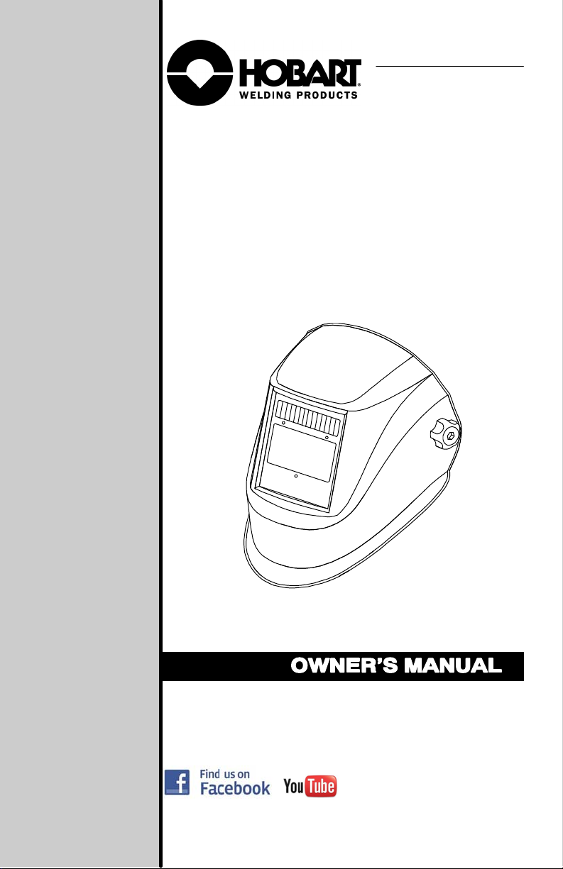
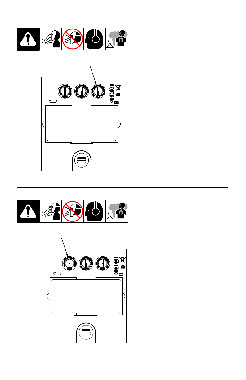
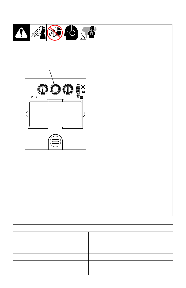
Before welding, adjust the auto-darkening lens sensitivity setting to meet the application.
Stop welding immediately if the auto-darkening lens does not darken when the arc is struck.
ARC RAYS can burn eyes and skin.
NOISE can damage hearing.
Noise from some processes or equipment can damage hearing.
Wear approved ear protection if noise level is high.

OM-281996 Page 2
WELDING HELMETS do not provide unlimited eye, ear, and
face protection.
Arc rays from the welding process produce intense visible and invisible (ultraviolet
and infrared) rays that can burn eyes and skin. Sparks fly off from the weld.
Use helmet for welding/cutting applications only. Do not use helmet for laser welding/cutting.
Use impact resistant safety spectacles or goggles and ear protection at all times when using
this welding helmet.
Do not use this helmet while working with or around explosives or corrosive liquids.
Do not weld in the overhead position while using this helmet.
Inspect the auto-lens frequently. Immediately replace any scratched, cracked, or pitted cover
lenses or auto-lenses.
Lens and retention components must be installed as instructed in this manual to ensure
compliance with ANSI Z87.1 protection standards.
READ INSTRUCTIONS.
Read and follow all labels and the Owner’s Manual carefully before in-
stalling, operating, or servicing unit. Read the safety information at the be-
ginning of the manual and in each section.
Use only genuine replacement parts from the manufacturer.
Perform installation, maintenance, and service according to the Owner’s Manuals, industry
standards, and national, state, and local codes.
FUMES AND GASES can be hazardous.
Welding produces fumes and gases. Breathing these fumes and gases can be
hazardous to your health.
Keep your head out of the fumes. Do not breathe the fumes.
Ventilate the work area and/or use local forced ventilation at the arc to remove welding fumes
and gases. The recommended way to determine adequate ventilation is to sample for the com-
position and quantity of fumes and gases to which personnel are exposed.
If ventilation is poor, wear an approved air-supplied respirator.
Read and understand the Safety Data Sheets (SDSs) and the manufacturer’s instructions for
adhesives, coatings, cleaners, consumables, coolants, degreasers, fluxes, and metals.
Work in a confined space only if it is well ventilated, or while wearing an air-supplied respirator.
Always have a trained watchperson nearby. Welding fumes and gases can displace air and
lower the oxygen level causing injury or death. Be sure the breathing air is safe.
Do not weld in locations near degreasing, cleaning, or spraying operations. The heat and rays
of the arc can react with vapors to form highly toxic and irritating gases.
Do not weld on coated metals, such as galvanized, lead, or cadmium plated steel, unless the
coating is removed from the weld area, the area is well ventilated, and while wearing an air-
supplied respirator. The coatings and any metals containing these elements can give off toxic
fumes if welded.
1-3. Proposition 65 Warnings
WARNING: Cancer and Reproductive Harm −www.P65Warnings.ca.gov

OM-281996 Page 3
1-4. Lens Shade Selection Table
Process Electrode Size
in. (mm) Arc Current
in
Amperes
Minimum
Protective
Shade No.
Suggested
Shade No.
(Comfort)*
Shielded Metal Arc
Welding (SMAW) Less than 3/32 (2.4)
3/32−5/32 (2.4−4.0)
5/32−1/4 (4.0−6.4)
More than 1/4 (6.4)
Less than 60
60−160
160−250
250−550
7
8
10
11
−−
10
12
14
Gas Metal
Arc Welding
(GMAW)
Flux Cored
Arc Welding
(FCAW)
Less than 60
60−160
160−250
250−500
7
10
10
10
−−
11
12
14
Gas Tungsten Arc
Welding (TIG) Less than 50
50−150
150−500
8
8
10
10
12
14
Air Carbon
Arc Cutting (CAC-A) Light
Heavy Less than 500
500−1000 10
11 12
14
Plasma Arc
Cutting (PAC) Less than 20
20−40
40−60
60−80
80−300
300−400
400−800
4
5
6
8
8
9
10
4
5
6
8
9
12
14
Plasma Arc Welding
(PAW) Less than 20
20−100
100−400
400−800
6
8
10
11
6−8
10
12
14
Reference: ANSI Z49.1:2012
* Start with a shade that is too dark to see the weld zone. Then, go to a lighter shade which gives a
sufficient view of the weld zone without going below the minimum.
1-5. Principal Safety Standards
Safety in Welding, Cutting, and Allied Processes, ANSI Standard Z49.1, is available as a free down-
load from the American Welding Society at http://www.aws.org or purchased from Global Engineering
Documents (phone: 1-877-413-5184, website: www.global.ihs.com).
Safe Practice For Occupational And Educational Eye And Face Protection, ANSI Standard Z87.1,
from American National Standards Institute, 25 West 43rd Street, New York, NY 10036 (phone:
212-642-4900, website: www.ansi.org).
Industrial Head Protection, ANSI/ISEA Standard Z89.1, from American National Standards Institute,
25 West 43rd Street, New York, NY 10036 (phone: 212-642-4900, website: www.ansi.org).

OM-281996 Page 4
SECTION 2 −SPECIFICATIONS
Viewing Field 3.82 x 1.85 in. (97 x 47 mm)
Reaction Time 0.00004 sec (1/25,000 sec)
Available Shades Darkened State: No. 9–13/Light State: No. 3
Provides Continuous UV And IR Protection (DIN 15)
Grind Mode Yes
Sensitivity Control Lo-Hi Adjustment For Varying Ambient Light And
Welding Arc
Delay Control Min-Max Adjustment Slows Lens Dark-To-Light State
Between 0.1 And 0.9 Seconds
Power Auto-On/Auto-Off
Low Battery Indicator Red LED Light Illuminates To Indicate 2−3 Days
Remaining Battery Life
Power Supply Solar Cell And Replaceable CR2450 Lithium Battery
Sensors Independent/Redundant (Three)
Operating Temperature 14F to 149F / −10C to +65C
When stored in extremely cold temperatures, warm
helmet to ambient temperature before welding.
Total Weight 19 oz (540 g)
Standards ANSI Z87.1-2015, CE EN379, CSA Z94.3-15
Warranty Two Years From Date Of Purchase (see Section 11)
Notes

OM-281996 Page 5
SECTION 3 −OPERATING INSTRUCTIONS
3-1. Helmet Controls
Remove protective films from
lens before welding.
1 Low Battery Indicator
(See Section 3-2)
2 Variable Shade Control (See
Section 3-4)
3 Sensitivity Control
(See Section 3-5)
4 Lens Delay Control
(See Section 3-3)
5 Weld/Grind Mode Switch (See
Section 3-6)
6 Grind Mode Indicator (See
Section 3-6)
42153
6
3-2. Low Battery Indicator
1
1 Low Battery Indicator
The low battery indicator lights when 2−3
days of battery life remain. If battery power
is low, install new CR2450 lithium batteries
(see Section 6).
The auto-darkening lens consumes
less than 1 microamp of battery power
when in the sleep mode. See Section
3-7 for more information on battery us-
age in the different power modes.

OM-281996 Page 6
3-3. Lens Delay Control
Place Weld/Grind mode switch
in Weld position (Section 3-6).
1 Lens Delay Control
The lens delay control is used to ad-
just the time for the lens to switch to
the clear state after welding.
The delay is particularly useful in
eliminatingbright after-rays present
in higher amperage applications
where the molten puddle remains
bright momentarily after welding.
Lens delay adjusts from min (0.1
second) to max (0.9 second).
1
3-4. Variable Shade Control (No. 9–13)
Place Weld/Grind mode
switch in Weld position (Sec-
tion 3-6).
1 Variable Shade Control
(No. 9–13)
Use the control to adjust the lens
shade in the darkened state. Use
the table in Section 1-4 to select
proper shade control setting
based on your welding process.
Start at the highest setting and
adjust lighter to suit the welding
application and your personal
preference.
1

OM-281996 Page 7
3-5. Sensitivity Control
Place Weld/Grind mode switch
in Weld position (Section 3-6).
1 Sensitivity Control
Use control to make the lens more
responsive to different light levels in
various welding processes. Use a
Mid-Range or 50-70% sensitivity
setting for most applications.
It may be necessary to adjust helmet
sensitivity to accommodate different
lighting conditions or if lens is flash-
ing on and off. Adjust helmet sensitiv-
ity as follows:
Adjust helmet sensitivity in light-
ing conditions helmet will be
used in.
Turn sensitivity control to lowest
setting.
Face the helmet in the direction
of use, exposing it to the sur-
rounding light conditions.
Gradually turn sensitivity setting
clockwise until the lens darkens,
then turn sensitivity control
counterclockwise until slightly
past setting where lens clears.
Helmet is ready for use. Slight
readjustmentmay be necessary
for certain applications or if lens
is blinking on and off.
1
Recommended Sensitivity Settings
Stick Electrode Mid-Range
Short Circuiting (MIG) Low/Mid-Range
Pulsed And Spray (MIG) Mid-Range
Gas Tungsten Arc (TIG) Mid/High-Range
Plasma Arc Cutting/Welding Low/Mid-Range
Grinding Place Weld/Grind Mode Switch In Grind Position

OM-281996 Page 8
3-6. Weld/Grind Mode Switch
1 Weld/Grind Mode Switch
2 Grind Mode Indicator
Place switch in Grind mode for grinding ap-
plications. To resume welding, place switch
in Weld mode. The Grind Mode indicator will
blink when helmet is in Grind mode.
Do not weld in the Grind mode; the lens
will not darken.
1
2
3-7. Power Modes
The auto-darkening lens has three
power modes: sleep (off), standby, and
on. The lens goes to sleep automatical-
ly when ambient light is low (less than
3 lux). The lens consumes less than 1
microamp of battery power when in the
sleep mode.
When ambient light exceeds10 lux, the
lens automatically changes to the
standby mode and is ready for welding.
The lens relies on the solar cell for pow-
er when in standby mode.
When welding begins, the lens auto-
matically turns on (darkens). In most
cases, the solar cell provides enough
power to operate the lens during weld-
ing. However, the lens may use both
solar and battery power when shade
control is at a high setting.
The lens returns to standby mode im-
mediatelyafter welding stops, and then
enters sleep mode if ambient lighting is
low (less than 3 lux).

OM-281996 Page 9
SECTION 4 −ADJUSTING HEADGEAR
There are four head-
gear adjustments:
headgear top, tight-
ness, angle adjust-
ment, and distance ad-
justment.
1 Headgear Top
Adjustment
Adjusts headgear for prop-
er depth on the head to en-
sure correct balance and
stability.
2 Headgear Tightness
Adjustment
To adjust, turn the adjust-
ing knob located on the
back of the headgear left or
right to desired tightness.
3 Angle Adjustment
Slots on the right side of the
headband provide adjust-
ment for the forward tilt of
the helmet. To adjust, lift
and reposition the control
arm to the desired position.
4 Distance Adjustment
5 Headgear Screw
Adjusts the distance be-
tween the face and the
lens. To adjust, loosen
headgearscrews and slide
headgearforward or back-
ward to one of the three
slots on the slider. Tighten
screws. (Both sides must
be equally positioned for
proper vision.)
1
2 4
53

OM-281996 Page 10
SECTION 5 −REPLACING THE LENS COVERS
5-1. Replacing Outside Lens Cover
!Never use the auto-darkening
lens without the inside and
outside lens covers properly
installed.Welding spatter will
damage the auto-darkening
lens and void the warranty.
1 Locking Tab
2 Lens Assembly
3 Outside Lens Cover
Remove lens assembly by sliding
the locking tab to the left. Remove
cartridge and lens cover.
Install new lens cover. Install lens
assembly and slide locking tab to the
right.
1
2
3

OM-281996 Page 11
5-2. Replacing Inside Lens Cover
!Never use the auto-darkening
lens without the inside and out-
side lens covers properly
installed. Welding spatter will
damage the auto-darkening
lens and void the warranty.
1 Lens Assembly
2 inside Lens Cover
Remove the lens cover holder (see
Section5-1). Remove lens assembly.
Remove the inside lens cover by pry-
ing the cover up at either thumbnail
opening at each side of the cover.
Slide cover it out of either side of
frame. Replace lens cover and rein-
stall the assembly in the helmet by re-
versing the above procedure.
Be sure the cover lens is seated
properly (flat) to prevent fogging.
1
2

OM-281996 Page 12
SECTION 6 −REPLACING THE BATTERY
The helmet is powered by solar
cells and a CR2450 lithium
battery.
1 Low Battery Indicator
The low battery indicator lights
when 2−3 days of battery life
remain.
If battery power is low, install
new CR2450 lithium battery.
2 Battery Cover
Slide the battery cover out and
remove the old battery.
Install new CR2450 lithium bat-
tery. Reinstall cover.
Be sure Positive (+) side of
the battery faces up (toward
inside of helmet).
1
Be sure Positive (+)
side of battery faces up.
2

OM-281996 Page 13
SECTION 7 −INSTALLING OPTIONAL MAGNIFYING LENS
1 Optional Magnifying Lens
Slide magnifying lens into the hel-
met retaining brackets as shown.
Align the magnifying lens with the
auto-darkening lens assembly.
To prevent lens fogging, install
flat side of magnifying lens to-
ward auto-darkening lens.
1
SECTION 8 −MAINTENANCE
NOTICE −Never use solvents or abrasive cleaning detergents.
NOTICE −Do not immerse the lens assembly in water.
The helmet requires little maintenance. However, for best performance clean
helmet after each use. Using a soft cloth dampened with a mild soap and water
solution, wipe the cover lenses clean. Allow to air dry. Occasionally, the filter
lens and sensors should be cleaned by gently wiping with a soft, dry cloth.

OM-281996 Page 14
SECTION 9 −TROUBLESHOOTING
Trouble Remedy
Not switching – auto-lens
stays light and will not
darken when welding.
Stop welding immediately. If power is on, review the sensitivity
recommendations and adjust sensitivity. Make sure helmet is not
in Grind mode. Clean lens cover and sensors of any obstructions.
Make sure the sensors are facing the arc; angles of 45or more
may not allow the arc light to reach the sensors.
Check battery and verify it is in good condition and installed pro-
perly. Also, check battery surface and contacts, and clean if ne-
cessary. Check battery for proper contact and gently adjust con-
tact points if necessary. This is particularly important if the helmet
has been dropped.
Not Switching – auto-lens
stays dark after the weld
arc is extinguished, or the
auto-lens stays dark when
no arc is present.
Fine-tune the sensitivity setting by making small adjustments to
the control by turning it toward the LO setting. In extreme light
conditions, it may be necessary to reduce the surrounding light
levels.
Sections of the auto-lens
are not going dark, distinct
lines separate the light and
dark areas.
Stop welding immediately: The auto-lens may be cracked which
can be caused by the impact of dropping the helmet. Weld spatter
on the auto lens may also cause cracking. (The lens may need to
be replaced; most cracked lenses are not covered by warranty).
Switching or Flickering –
the auto-lens darkens then
lightens while the welding
arc is present.
Review the sensitivity setting recommendations and increase the
sensitivity if possible. Be sure the arc sensors are not being
blocked from direct access to the arc light. Check the lens cover
for dirt and spatter that may be blocking the arc sensors. Increas-
ing Lens Delay slightly may also reduce switching.
Inconsistent or lighter
auto-lens shading in the
dark-state, noticeable on
the outside edges and
corners.
Referred to as an angle of view effect, auto-darkening lenses
have an optimum viewing angle. The optimum viewing angle is
perpendicular or 90to the surface of the auto-lens. When that
angle of view varies in the dark-state, welders may notice slightly
lighter areas at the outside edges and the corners of the lens. This
is normal and does not represent any health or safety hazard.
This effect may also be more noticeable in applications where
magnifying lenses are used.

OM-281996 Page 15
SECTION 10 −PARTS LIST
2
4
5
1
3
Figure 10-1. Creator Series Auto-Darkening Welding Helmet

OM-281996 Page 16
Description
Part
No.
Item
No. Quantity
Figure 10-1. Creator Series Auto-Darkening Welding Helmet
1 770843 Headgear 1......... ... ..............................................
2770274 Diopter Lens 150X 1....... ... ......................................
770275 Diopter Lens 175X 1......... ... ......................................
770276 Diopter Lens 200X 1......... ... ......................................
770277 Diopter Lens 250X 1......... ... ......................................
3 770845 Auto-Darkening Lens 1......... ... ....................................
770284 Battery, CR2450 1........... ... ........................................
4 770883 Frame, Lens Replacement 1......... ... ...............................
5 770856 Kit, Clear Protective Lens 1......... ... ................................
Optional
SECTION 11 −LIMITED WARRANTY
LIMITED WARRANTY – Subject to the terms and conditions below, Miller Electric
Mfg. LLC, dba Hobart Welding Products, Appleton, WI, warrants to its original retail
purchaser that the new Hobart equipment sold after the effective date of this limited
warranty is free of defects in material and workmanship at the time it is purchased
at the retailer. THIS WARRANTY IS EXPRESSLY IN LIEU OF ALL OTHER WAR-
RANTIES, EXPRESS OR IMPLIED, INCLUDING THE WARRANTIES OF MER-
CHANTABILITY AND FITNESS.
Hobart auto-darkening lens helmets are warranted for two (2) years from the date
of purchase. Proof of purchase is required for warranty transactions so it is im-
perative that a copy of the original invoice or sales receipt be retained.
For warranty transactions, contact your original Hobart retailer or call
1−800−332−3281
Effective January 1, 2018
Hob Helm 2018-01

Notes
Work like a Pro!
Pros weld and cut
safely. Read the
safety rules at
the beginning
of this manual.

Miller Electric Mfg. LLC
An Illinois Tool Works Company
1635 West Spencer Street
Appleton, WI 54914 USA
Phone: 800-332-3281
Visit our website at
www.HobartWelders.com
ORIGINAL INSTRUCTIONS −PRINTED IN USA 2018 Miller Electric Mfg. LLC 2018-01
This manual suits for next models
2
Table of contents
Other Hobart Motorcycle Accessories manuals
Popular Motorcycle Accessories manuals by other brands

hepco & becker
hepco & becker 6607602 00 01 manual

Nolan
Nolan N104 Absolute Safety and instructions for use

Triumph
Triumph My Triumph Connectivity Owner's handbook

PUIG
PUIG 9729 quick start guide

KTM Power Parts
KTM Power Parts 90507908000 Information

BestRest Products
BestRest Products R11 GS Series installation manual