Hobbytec PJR Series Programming manual

1
HZ1696-E
Assemblingmanual
PJR-seriesWidebeam/Tripletype
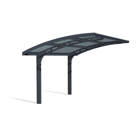
Carport
Thank you very much for choosing our company's products.
Please be sure to thoroughly read these instructions for assembly in order to properly and smoothly assemble or attach this product.
Notices are the important contents for securing the performance of the products, the function, the strength and safety. Please be
sure to keep the notices when installing.
Construction shall be implemented by professionals. Problems may occur if the product is installed by someone without the
proper knowledge.
Precautions during installation
□The carport is a simple garage. Do not change or remodel it for storage, recreational or residential purposes.
□The snow accumulation strength is 600N/m2(61.2kg/m2) which corresponds to 20cm of fresh snowfall (specific weight 0.3). Do
not install in heavy snow area.
□Do not install it in the place where snow slides down from the building roof directly. There is a possibility that products are
damaged by snow falling.
□When installing it besides concrete wall, etc., keep the enough clearance between the product and the wall due to not clash
each other during strong wind.
□Do not install it in the place where the strong wind blows up the roof.
□When installing it, recommending to installing its front frame face to the building due to reduce the wind effect.
□Positioning the posts so that they do not affect underground objects (water supply, drain pipes, etc.).
□When moving the posts, please follow the company specifications.
□Install it so that the exhaust of hot-water supply, heating and/or the car do not hit directly to the products and do not retain
around products. There is a possibility that the surface abnormality occurs as the coating film stripping.
Name of parts
Please be sure to return the instruction manual in its original package to the owner after explaining product operation
procedures, maintenance and inspection methods.
Notice
Gutter
Roof panel
Post
Side frame Roof retainerMain frame
Roof rafter
Beam
enoughspace
enoughspace
concretewalletc

2
sea
sand
cement
enhancer water-
reducingcryopro
tectant
rust dust
oil
water
Precautions during construction
□Follow the instructions and be sure that all the specified screws and bolts for assembly are tightened securely
□Tighten the M8 bolts about 13Nm (130kgfcm) tightening torque.
□Do not use anything other than the specified parts or optional parts.
□The foundation should comply with or exceed dimension specifications.
□Allow sufficient curing time for the concrete (4 to 7 days) and do not place heavy objects on it or subject it to vibrations during
the curing period.
□Be sure to keep the note below to prevent aluminum materials corrode.
(1) Do not use sea sand for the foundation since it contains
salt and may cause corrosion. Do not use a cement
enhancer, water-reducing agent or cryoprotectant. They
may cause the posts to corrode.
(3) Be sure to provide gravel for the foundation to allow
drainage, insert water drainage holes (φ5) at the base of
the posts and foundation. Failure to do so may lead to
water accumulation inside the posts and damage them if
the water freezes and expands inside.
(2) Immediately wipe off any mortar or stains from the surface
of aluminum parts since they may cause corrosion.
water
drainage
hole
□Be sure to put the sealant glue as the following. (Please prepare the sealing materials on-site)
(1) Wipe off any stains from
the sealing part.
(2) Be sure to apply a
sealant, as specified.
(3) After putting the sealant
glue on the hole made in
its all wall body, fully
tighten the screw.
(4) Seal completely deep
enough and finish the
surface with a pallet.
Necessary tools and materials for installation
□When the G.L(Ground line)is steep, be sure to keep the depth of the post at the lowest level.
□After construction, check the products to see if the bolts, screws, nuts, etc. loosen or any dangerous places exist.
□Be sure to check if the product has scratches, dents or dint.
□Be sure to explain product operation procedures, maintenance and inspection methods to the owner.
□Electric drill, Drill
□Ratchet wrench, Adjustable end wrench
□Electric Screwdriver
□Measure, Level, Plumb bob, Cutter, Pillar, Plastic hammer
□Foundation materials (Cement, Aggregate, etc)
□Sealant, Caulk gun, pallet
□Cropper or Saw
□Please prepare tools and materials as needed
sealing
sealing

2600856 856
W43=4312
726 715
29001063.5 1063.5
W50=5027
726 715
33001221 1221
W57=5742
726 715
1775 1775738.5 738.5
W50=5027
726 715
2000 2000871 871
W57=5742
726 715
3
G.L G.L
G.L
G.L G.L
43 size 50 size
57 size
57 size
50 size
■Length dimension(W) and post standard position (Post could be changed as the dimension of ←→.)
Dimension, position of posts and base dimension
Dimension, position of post
For D36 to D60(Wide beam)
For D72/D80 triple type
100 100
100 100
100
100
100
100
100
100
100
100
100 100
100
100
100
100
100
100 100
100 100
100

H18:1800H23:2250H28:2750 H18:1800H23:2250H28:2750
H18:1800H23:2250H28:2750
D36:3627 D42:4223
D48:4815 D51:5091
D54:5406 D60:5995
D72:7200
D80:8000
H+(396)
H18:2196H23:2646H28:3146
H+(448)
H18:2248H23:2698H28:3198
H+(511)
H18:2311H23:2761H28:3261
H+(541)
H18:2341H23:2791H28:3291
H+(574)
H18:2374H23:2824H28:3324
H+(637)
H18:2437H23:2887H28:3387
H+(630)
H18:2430H23:2880H28:3380
H+(715)
H18:2515H23:2965H28:3465
140 140
140
140
140
150
150
140
H+(100)
H18:1900H23:2350H28:2850
H+(100)
H18:1900H23:2350H28:2850
H+(100)
H18:1900H23:2350H28:2850
H+(100)
H18:1900H23:2350H28:2850
H+(100)
H18:1900H23:2350H28:2850
H+(100)
H18:1900H23:2350H28:2850
H+(98)
H18:1898H23:2348H28:2848
H+(98)
H18:1898H23:2348H28:2848
H+(245)
H18:2045H23:2495H28:2995
H+(263)
H18:2063H23:2513H28:3013
H+(326)
H18:2126H23:2576H28:3076
H+(355)
H18:2155H23:2605H28:3105
H+(388)
H18:2188H23:2638H28:3138
H+(451)
H18:2251H23:2701H28:3201
H+(440)
H18:2240H23:2690H28:3190
H+(524)
H18:2324H23:2774H28:3274
4
G.L G.L
G.L
G.L
G.L
G.L
G.LG.L
Dimension, position of posts and base dimension
■Depth dimension(D), height dimension(H)
〔depth 36・42・48・51・54・60・72・80size〕

140
150(D72、D80)
500
550
(D72、D80)
300
D
95
500
550
(D72、D80)
E
500
550
(D72、D80)
A=more than 200
400
more than 100
more than 50
95 The projections which prevent floating
steel rod
more than 50
more than 100
more than 50
A=more than 200
500
550
(D72、D80)
The projections which prevent floating
140
150(D72、D80)
steel rod
450
more than 50
Base dimension
1.In case of concrete floor
2.In case of no concrente floor or no correspond to above condition.
■Depth direction ■Length direction
※Please install under below condition in case of concrete floor.
①Thickness of concrete floor is more than 100mm.
②Steel rod and welding wire net are arranged in concrete floor.
③Dimension of projection which prevents floating at 4 rounds is more than 50mm×50mm.
④Distance(A)from outside edge of base to around concrete floor is more than dimension specifications.
5
43
50
57
Length:W
①
①
①
36
①
①
①
42
②
②
②
48
②
②
②
51
Depth:D
②
②
③
54
③
③
③
60
④
④
④
72
④
④
④
80
D dimension
E dimension
600
800
①
700
800
②
1300
800
③
900
800
④
■In case of 100kN/㎡endurance strength of ground
D dimension
E dimension
600
1050
①
800
1050
②
1250
1050
③
1100
1050
④
■In case of 50kN/㎡endurance strength of ground

6
U shape gutter 2 partsUshape gutter 4 partsU shape gutter 1 partsNo U shape gutter
U shape gutter 2 partsU shape gutter 1 parts
No U shape gutterNo U shape gutter
U shape gutter 1 parts
Post type ①
PJRH-18A
PJRH-23A
PJRH-18A-1
PJRH-23A-1
②
PJRH-18B
PJRH-23B
PJRH-18B-1
PJRH-23B-1
③
PJRH-18C
PJRH-23C
PJRH-18C-1
PJRH-23C-1
④⑤
PJRH-28F-1 PJRH-28G-1
②
PJWT-54B-2
③
PJWT-60C-2
④
PJWT-51E-2
PJWT-54E-2
PJWT-60E-2
PJTT-72E-3
PJTT-80E-3
Section
Parts ID
Main frame type
①
PJWY-W50A-4
PJWY-W57A-4
②
PJWY-W43B-2
PJWY-W43B-3
③
PJWY-W50C-2
PJWY-W50C-3
④
PJWY-W43E-4
PJWY-W50E-4
PJWY-W57E-2
PJWY-W57E-3
PJWY-W57E-4
Section
Parts ID
Beam type ①
PJWT-36A-2
PJWT-42A-2
PJWT-48A-2
PJWT-51A-2
PJWT-54A-2
Section
Parts ID
Type Component parts
Post Beam Main frame
Standard post
①
④
①
②
④
③
④
②
③
④
②
③
④
②
③
④
②
③
④
②
③
④
④
①
Depth D
36
42
48
51
54
60
72
80
43
50
57
43
50
57
43
50
57
43
50
57
43
50
57
43
50
57
50
57
50
57
①
②
①
②
①
②
③
①
②
①
②
①
②
③
⑥
⑦
Length W Long post
Extra-long post
Body size
Parts instruction guide
Post・beam・main frame list

18
A part
Middle frame cap
Small truss screw
5×10×10
(Roof rafter set)
Roof retainer (middle)
(Beam・depth set)
Gutter
Middle frame
Roof retainer (end)
(
Beam・depth set
)
Sealing
Sealing
Sealing
Sealing
Rain water cover Sealing
Sealing
Middle frame
Side frame
Middle frame
Side frame
Roof retainer
(end)
Roof retainer
(middle)
Small truss screw
5×10×10
Small truss screw
5×10×10
(Roof rafter set)
■Detailed section drawing
Peel off the back sheet of
the rain water cover and
attach to the end upper face
of the middle frame and do
sealing work around it.
Do sealing work to the
insert part of cap into
middle frame and side
frames.
※When screwing the roof retainer (end), insert the
end part of roof retainer into the gutter cap before
screwing the second screw from the post side.
■A part
detailed figure
Do sealing work to the insert part of roof retainer (end) into middle frame.
Step2
Step3 Step3
12
Installation of roof retainer
Insert the end of roof retainer into the
middle frame, and fix from the middle
frame side with small truss screw 5x10x10.
Step1
If the screw of installing the roof retainer is tighten
too much, the screw will run idle. Tightening torque
is about less than 1.5Nm (15kgfcm).
If the screw head leans when installing the roof
retainer, it will cause water leakage (water will enter
from the screw head clearance), so install it not to
make clearance.
Notice
For D36 to D60(Wide beam) For D72/D80 triple type
7
PJWY-W43B-2
PJWY-W43B-3
PJWY-W43E-4
PJWY-W50A-4
PJWY-W50C-2
PJWY-W50C-3
PJWY-W50E-4
PJWY-W57A-4
PJWY-W57E-2
PJWY-W57E-3
PJWY-W57E-4
PJRY-W43○-○
PJRY-W50○-○
PJRY-W57○-○
1
2
3
4
2
3
4
2
3
4
5
6
7
ShapeDescription
Content
Parts ID Quantity
Post set
(standard)
PJRH-18A
PJRH-18B
PJRH-18C
Post set
(1pc)
(standard)
PJRH-18A-1
PJRH-18B-1
PJRH-18C-1
Post set
(long post)
PJRH-23A
PJRH-23B
PJRH-23C
2
1
1
1
1
2
1
1
1
1
1
1
1
Post
Post
Post
Round gutter
GA4923
Instruction manual
Post
Round gutter
GA4923
Round gutter
GA4923
Instruction manual
Post set
(1pc)
(long post)
PJRH-23A-1
PJRH-23B-1
PJRH-23C-1
Post set
(
extra-long post
)
PJRH-28F-1
PJRH-28G-1
Post
Round gutter
GA4923
Round gutter
GA4923
Instruction manual
ShapeDescription
Content
Parts ID Quantity
2
1
PJWY-W43B-2
PJWY-W43B-3
PJWY-W43E-4
PJWY-W50A-4
PJWY-W50C-2
PJWY-W50C-3
PJWY-W50E-4
PJWY-W57A-4
PJWY-W57E-2
PJWY-W57E-3
PJWY-W57E-4
12
18
24
28
14
21
28
32
16
24
32
Length set
PJWY-W43B-2
PJWY-W43B-3
PJWY-W43E-4
PJWY-W50A-4
PJWY-W50C-2
PJWY-W50C-3
PJWY-W50E-4
PJWY-W57A-4
PJWY-W57E-2
PJWY-W57E-3
PJWY-W57E-4
Gutter
Main frame
Panel holder
(middle)
L=645
Panel holder
(end)
L=300
Round gutter
GA4923
Roof panel cushion
GB8274
Parts contents
□Please open the captioned carton and check all contents in advance.
□Please check the parts defective or any damage.
□After opening the carton boxes, please store the products so that
they are not damaged.
□We packed some extra screw in the parts box.(x)number is
necessary Q'ty for installation.
When △mark is P, it’s the polycarbonate panel.
When △mark is PS, it’s polycarbonate panel (SI)
When △mark is CP, it’s the heat protection
polycarbonate panel.
When △mark is CH, it’s heat protection FRP (SI)

8
ShapeDescription
Content
Parts ID Quantity
Middle frame set
PJWM-W43
PJWM-W50
PJWM-W57
PJTM-W50
PJTM-W57
Beam・depth set
PJWT-36A-2
PJWT-42A-2
PJWT-48A-2
PJWT-51A-2
PJWT-51E-2
PJWT-54A-2
PJWT-54B-2
PJWT-54E-2
PJWT-60C-2
PJWT-60E-2
Beam set
PJTT-72E-3
PJTT-80E-3
Side frame
set
PJTE-72
PJTE-80
Corner parts
set
PJR-CBA
PJR-CBC
ShapeDescription
Content
Parts ID Quantity
Roof rafter
set
PJWU-4336
PJWU-4342
PJWU-4348
PJWU-4351
PJWU-4354
PJWU-4360
PJWU-5036
PJWU-5042
PJWU-5048
PJWU-5051
PJWU-5054
PJWU-5060
PJTU-5072
PJTU-5080
PJWU-5736
PJWU-5742
PJWU-5748
PJWU-5751
PJWU-5754
PJWU-5760
PJTU-5772
PJTU-5780
Middle frame
Beam
Beam
Side frame
Side frame
Roof retainer
(end)
Drilling screw
4×10×8
Roof retainer
(end)
Small truss screw
5×1 0×1 0
10
12
14
10
12
14
88(84)
103(98)
118(113)
101(96)
118(113)
134(129)
113(108)
132(127)
151(146)
134(129)
149(144)
172(167)
187(182)
191(186)
214(209)
147(142)
164(159)
189(184)
206(201)
210(205)
235(230)
361(359)
395(390)
160(155)
179(174)
206(201)
225(220)
229(224)
256(251)
397(392)
435(430)
PJWU-43○○
PJWU-50○○
PJTU-50○○
PJWU-57○○
PJTU-57○○
PJWU-43○○
PJWU-50○○
PJTU-50○○
PJWU-57○○
PJTU-57○○
PJWU-4336
PJWU-4342
PJWU-4348
PJWU-4351
PJWU-4354
PJWU-4360
PJWU-5036
PJWU-5042
PJWU-5048
PJWU-5051
PJWU-5054
PJWU-5060
PJTU-5072
PJTU-5080
PJWU-5736
PJWU-5742
PJWU-5748
PJWU-5751
PJWU-5754
PJWU-5760
PJTU-5772
PJTU-5780
PJWU-4336
PJWU-4342
PJWU-4348
PJWU-4351
PJWU-4354
PJWU-4360
PJWU-5036
PJWU-5042
PJWU-5048
PJWU-5051
PJWU-5054
PJWU-5060
PJTU-5072
PJTU-5080
PJWU-5736
PJWU-5742
PJWU-5748
PJWU-5751
PJWU-5754
PJWU-5760
PJTU-5772
PJTU-5780
Corner
bracket
GB8062
GB8064
1
2
2
4
3
4
4
Roof rafter
Roof retainer
(middle)
2

9
Roof panel
set
PJRY-△18-3
PJRY-△21-3
PJRY-△24-3
PJRY-△27-3
PJRY-△30-3
PJRY-△18-4
PJRY-△21-4
PJRY-△24-4
PJRY-△27-4
PJRY-△30-4
PJRY-△36-2
PJRY-△40-2
Parts box
PJWB
PJTB
PJTB
only
3
4
2
4
6
4
6
28
48
PJRY-△○○-3
PJRY-△○○-4
PJRY-△○○-2
PJWB
PJTB
PJWB
PJTB
PJWB
PJTB
2
48
72
PJWB
PJWB
PJTB
Anchor rod
GA0073
Post cap
GB8071
GB8072
Hole seal
φ1 4
GA0150
Hexagon bolt
(
with spring washer
,
washer)
M8×25
ES0249
Elbow
GA4932
Drain elbow
GA6461
Saddle
GB8077
Gutter cap
GB8075
Rain water
cover
GB8078
Gutter attachment
GA4929
Gasket
GA4930
11(10)
Caution label
GLZ20C
Snow label
HY0177
Product name label
HY0173
Drilling screw
4×10×8
Glue
GA4934
Assembling manual
Beam connecting
bracket
GB8079
Support plate
GB8080
Middle frame cap
GB8076
Hexagon bolt
M8×85-22
Cap nut
M8
Washer M8
Spring washer
M8
Roof panel
GB4107
(
Polycarbonate
:AO,BR)
GB8224
(
Polycarbonate:SI
)
GB4575
(
Heat protection
polycarbonate
)
GB5626
(
Heat protection
FRP:SI
)
1
1
1
1
1
6
3
2
12
12
24
12
RightLefteach2pc
2
2
4
2
6
ShapeDescription
Content
Parts ID Quantity ShapeDescription
Content
Parts ID Quantity
16
aa
3.5(guide)
AA
B part
diagonal
dimension
Gutter
Middle frame
Roof panel ①
②
Roof rafter
Side frame
U-shape gutter
Panel
Roof rafter
※Check post interval, flat and the diagonal dimension of the roof is
equal.
※In case diagonal dimension of the roof is not equal, loosen
the screws of the middle frame, gutter, main frame and beam
and adjust them.
■A-A’ section drawing ■B part detailed drawing
※When installing roof panels, please be noted below.
10
Installation of roof panels
Before installing the roof panels
Insert the roof panel into the middle
frame and then set on the gutter side.
※Adjust the roof panel end to the
U-shape gutter.
※Sort the panel equally right and left. Otherwise
the expansion of panels resulting from
temperature changes causes the noise.
In case of polycarbonate (SI) and FRP panel,
attach the unevenness side down. In case of
polycarbonate (AO/BR) and heat protection
polycarbonate, there are no two sides because
of both sides weatherproof.
Notice

10
For D36 to D60 this bolt
doesn’t need.
Connect between post and
beam with corner bracket and
fix it with hexagon bolts M8x25.
For D36 to D60(Wide beam)
Insert the post into the base
hole, and fix with support
stand not to fall down.
Step1
Check if it is flat
and vertical, and
cast concrete.
Step3
Install the beam
connecting parts to beam.
Step2
For D72/D80 triple type
Wide beam type installation procedure
1Installation of posts and beams
2Installation to base hole
Insert the post into
the base hole, and
fix with support
stand not to fall
down.
Step1
Check if it is flat
and vertical, and
cast concrete.
Step2
Install as the side which the caution
label is attached comes inside.
Beam
Beam connecting bracket
(Parts box)
Washer M8
(Parts box)
Beam
Hexagon bolt
M8×85-22
(Parts box)
Washer M8
(Parts box)
Spring washer M8
(Parts box)
Cap nut
M8(Parts box)
Hexagon bolt
M8×25
(Parts box)
Anchor rod
Corner bracket
(Corner parts set)
Post
Supportstand
Supportstand
Caution label

14
①
②
Insert
Sealing
Drilling screw
4×10×8
(Roof rafter set)
Drilling screw
4×10×8
(Roof rafter set)
Middle frame
Gutter
Side frame
Sealing
Sealing
Main frame
Middle frame
Gutter
Gutter
Gutter
Gutter cap(Parts box)
Side frame
Main frame
Gutter cap Side frame
Install the side frame to the
gutter and main frames
using guide holes with
drilling screws 4x10x8.
Step2
Insert the side frame
into the middle
frame and gutters
and fix with drilling
screws 4x10x8.
Step2
Attach the gutter cap into
the gutter.
Step1
8Installation of side frame
After installing step2 do sealing
work to the gutter.
Step3
■Detailed figure of the sealing part
indicates the sealing part.
For D36 to D60(Wide beam)
For D72/D80 triple type
11
Be sure to put the
labels in visible
position.
※In case the clothes hanger is
installed, put the caution label
not to overlap it.
Small truss screw
5×10×10
■Detailed figure
Attach the post cap onto the
post.
Install the gutter to the corner
bracket with small truss screw
5x10x10, and put the product
name label to the gutter.
3Attaching the post cap
In case of installing the post other than the post standard position.
①Make the hole (φ5.5) adjusting the post position
and screw it.
②Put the hole seals on the unnecessary holes.
4Installation of gutter
Hole seal
(Parts box)
Gutter
Small truss screw
5×10×10
(Roof rafter set)
Caution label(Parts box)
Snow caution label(Parts box)
Post
30
Product name label
(Parts box)
Post cap
Post cap(Parts box)
Beam

12
Install the middle frame to the beam
adjusting the holes with small truss
screw 5x10x10.
Peel the back sheet of support plate
and put the support plate on the middle
frame after adjusting to the holes of
support plate and middle frame fin.
Step1
Attach the cap to the end of middle
frame.
Step3
Install the middle frame on the beam with
small screw 5x10x10 adjusting the holes
of middle frame fin and pre-holes on the
beam. (Be careful of the kind of screws.)
Step2
5Installation of middle frame
In case of installing the post other than the post standard position.
①Make the hole (φ5.5) adjusting the post position
and screw it.
②Put the hole seals on the unnecessary holes.
For D36 to D60(Wide beam)
For D72/D80 triple type
Middle frame cap
(Parts box)
Support plate
Beam connecting bracket
Middle frame
Middle frame
Middle frame
Small truss screw
5×10×10
(Roof rafter set)
Small truss screw
5×10×10
(Roof rafter set)
30
Beam
Beam
Middle frame
Hole seal(Parts box)

13
A view
Mark-off lines
352.5(end) 715(middle) 715
Small truss screw
5×10×10
(Roof rafter set)
30
Main frame
Main frame
Roof panel cushion
Roof panel
cushion
Main frame
Main frame
Fin
U-shape gutter
U-shape gutter
Beam
Hole seal
(Parts box)
Main frame
Beam
Make the φ5.5 holes on the main frame adjusting the U-shape gutter on the beam and main frame, and screw it. (A figure)
In case of the installation other than the post standard position, put the hole seals on the unnecessary hole. (B figure)
■Afigure ■Bfigure
■A view drawing
※Attach the roof panel cushions
adjusting the gutter part.
※Push the cushion onto the top
face and attach it firmly not to
be come off.
Attach the roof panel cushions on the mark-off
lines of top face of all the main frames.
6Attaching the roof panel cushions
7Installation of main frame
Gutter side
Main frame side
※Install it the fin of the main
frame toward the gutter side.
Install the main frame to the
beam adjusting the guide hole
with small truss screw 5x10x10.
In case of installing the post other than the post standard position.

14
①
②
Insert
Sealing
Drilling screw
4×10×8
(Roof rafter set)
Drilling screw
4×10×8
(Roof rafter set)
Middle frame
Gutter
Side frame
Sealing
Sealing
Main frame
Middle frame
Gutter
Gutter
Gutter
Gutter cap(Parts box)
Side frame
Main frame
Gutter cap Side frame
Install the side frame to the
gutter and main frames
using guide holes with
drilling screws 4x10x8.
Step2
Insert the side frame
into the middle
frame and gutters
and fix with drilling
screws 4x10x8.
Step2
Attach the gutter cap into
the gutter.
Step1
8Installation of side frame
After installing step2 do sealing
work to the gutter.
Step3
■Detailed figure of the sealing part
indicates the sealing part.
For D36 to D60(Wide beam)
For D72/D80 triple type

10
For D36 to D60 this bolt
doesn’t need.
Connect between post and
beam with corner bracket and
fix it with hexagon bolts M8x25.
For D36 to D60(Wide beam)
Insert the post into the base
hole, and fix with support
stand not to fall down.
Step1
Check if it is flat
and vertical, and
cast concrete.
Step3
Install the beam
connecting parts to beam.
Step2
For D72/D80 triple type
Wide beam type installation procedure
1Installation of posts and beams
2Installation to base hole
Insert the post into
the base hole, and
fix with support
stand not to fall
down.
Step1
Check if it is flat
and vertical, and
cast concrete.
Step2
Install as the side which the caution
label is attached comes inside.
Beam
Beam connecting bracket
(Parts box)
Washer M8
(Parts box)
Beam
Hexagon bolt
M8×85-22
(Parts box)
Washer M8
(Parts box)
Spring washer M8
(Parts box)
Cap nut
M8(Parts box)
Hexagon bolt
M8×25
(Parts box)
Anchor rod
Corner bracket
(Corner parts set)
Post
Supportstand
Supportstand
Caution label
15
Roof rafter
Middle frame
Gutter
B part
C part
C part
A part
Main frame
U-shape gutter
Roof rafter
guide fin
U-shape gutter U-shape gutter
Drilling screw
4×10×8
(Roof rafter set)
■A part detailed figure
■Roof rafter drawing of the
middle frame and gutter part
※Fix the roof rafter firmly adjusting
the processing parts.
■B part detailed drawing ■C part detailed drawing
Screw it guiding the U-shape gutter
of the gutter at B part (step2).
Screw it guiding the U-shape gutter
of the main frame at C part (step3).
Screw it guiding the U-shape
gutter of the middle frame at
A part (step1).
Set the roof rafter to the processing
part of the middle frame. Strike the
end to the guide fin of the middle
frame and screw it.
Step1
9Installation of roof rafter
Screw to the gutter.
Step2
Screw it to the
main frame.
Step3

16
aa
3.5(guide)
AA
B part
diagonal
dimension
Gutter
Middle frame
Roof panel ①
②
Roof rafter
Side frame
U-shape gutter
Panel
Roof rafter
※Check post interval, flat and the diagonal dimension of the roof is
equal.
※In case diagonal dimension of the roof is not equal, loosen
the screws of the middle frame, gutter, main frame and beam
and adjust them.
■A-A’ section drawing ■B part detailed drawing
※When installing roof panels, please be noted below.
10
Installation of roof panels
Before installing the roof panels
Insert the roof panel into the middle
frame and then set on the gutter side.
※Adjust the roof panel end to the
U-shape gutter.
※Sort the panel equally right and left. Otherwise
the expansion of panels resulting from
temperature changes causes the noise.
In case of polycarbonate (SI) and FRP panel,
attach the unevenness side down. In case of
polycarbonate (AO/BR) and heat protection
polycarbonate, there are no two sides because
of both sides weatherproof.
Notice

17
For end partFor middle part
Processing part
Drilling screw
4×10×8
(Roof rafter set)
18 70
Panel holder (end)
(Length set)
Panel holder (middle)
(Length set)
Gutter
Side frame Gutter
Panel holder
(middle)
Panel holder
(end)
Roof rafter
■Position of the panel holder
11
Installation of panel holder
Install the panel holders adjusting the U-shape gutter of gutter frame as a guide, and fix with drilling screw 4x10x8.
※Insert the processing part of panel holder to the roof rafter (middle) and install it.

18
A part
Middle frame cap
Small truss screw
5×10×10
(Roof rafter set)
Roof retainer (middle)
(Beam・depth set)
Gutter
Middle frame
Roof retainer (end)
(
Beam・depth set
)
Sealing
Sealing
Sealing
Sealing
Rain water cover Sealing
Sealing
Middle frame
Side frame
Middle frame
Side frame
Roof retainer
(end)
Roof retainer
(middle)
Small truss screw
5×10×10
Small truss screw
5×10×10
(Roof rafter set)
■Detailed section drawing
Peel off the back sheet of
the rain water cover and
attach to the end upper face
of the middle frame and do
sealing work around it.
Do sealing work to the
insert part of cap into
middle frame and side
frames.
※When screwing the roof retainer (end), insert the
end part of roof retainer into the gutter cap before
screwing the second screw from the post side.
■A part
detailed figure
Do sealing work to the insert part of roof retainer (end) into middle frame.
Step2
Step3 Step3
12
Installation of roof retainer
Insert the end of roof retainer into the
middle frame, and fix from the middle
frame side with small truss screw 5x10x10.
Step1
If the screw of installing the roof retainer is tighten
too much, the screw will run idle. Tightening torque
is about less than 1.5Nm (15kgfcm).
If the screw head leans when installing the roof
retainer, it will cause water leakage (water will enter
from the screw head clearance), so install it not to
make clearance.
Notice
For D36 to D60(Wide beam) For D72/D80 triple type

19
①②③④⑤⑥⑦⑧⑨⑩⑩⑨⑧⑦⑥⑤④③②①
Side frame
Middle frame
Gutter
Middle frame
Roof retainer (end)
Roof retainer
(middle)
Small truss screw 5×15×10
(Panel support set)
Roof panel support
(Panel support set)
Roof retainer Side frameRoof panel support
Small truss screw 5×18×12
(Panel support set)
Roof panel support
(Panel support set)
Side frame
Roof retainer
Roof panel support
(Panel support set)
Gutter
Gutter
Gutter
Install the panel supports with small
truss screw 5x15x10.
Overlap the panel supports and
install with small screw
5x18x12.
※For D72 and D80 install the panel support adjusting the holes of roof retainers.
Step1
Step2
For D72 install the panel support at the position of 5th and 9th
hole from gutter.
For D80 install the panel support at the position of 5th and 10th
from gutter.

20
G.L
Round gutter
(Post set)
Drilling screw
4×10×8
(Parts box)
Sealing SealingSealing
Saddle(Parts box)
Drain elbow
(Parts box)
Elbow(Parts box)
Round gutter
(Length set)
Drilling screw 4×10×8
(Parts box)
Gutter attachment
(Parts box)
Gasket
(Parts box)
Sealing
The length of round gutter1 differs depending on the post position.
Cut it proper length on-site and use it.
13
Attaching the round gutter parts
Blinder side
Gutter side
①Crush the drain part with wood
hammer and driver at the position for
installing gasket.
※In case that it could not crush, use
electric drill and hit the part again
②Screw the gutter attachment and do
sealing work at the screw part.
※Be sure to seal around screws in
order to prevent danger when
cleaning as well as for water proof.
③Use glue in the parts
box for rain gutter
parts.
Blinder side
Gutter side
■The round gutter length 1 as a guide at the standard post position.
W43 type: 1=196
W43 type: 1=404
W50 type (Triple): 1=78
W57 type: 1=562
W57 type (Triple): 1=211
Do sealing work all around drain part on the blinder side.
This manual suits for next models
14
Popular Tent manuals by other brands

ShelterLogic
ShelterLogic MaxAP 23521 Assembly instructions

PahaQue
PahaQue A-Frame Trailer Side Tent Setup instructions

Palram
Palram CANOPIA SOPHIA 3x7 How to assemble

Coleman
Coleman 9271A163 instructions

Palram
Palram CANOPIA SOPHIA 3x5 / 1x1.6 How to assemble

Dancover
Dancover SEMI PRO 6x12m quick start guide