Hochiki America Corporation FN-600ULX User manual

140 58th St.
FN-600ULX
Power Supply/Charger
Installation Guide
Altronix Corp.
Rev. 120104

- 2 -
Overview:
The FN-600ULX is a power supply that converts a 115VAC / 60Hz input to a 12VDC or 24VDC regulating output
(see specifications below).
Agency Listings:
•
UL File # S4707:
Specifications:
Battery Backup
(cont’d)
:
•
Maximum charge current 0.7 amp.
UL Listed for Access Control System Units (UL 294).
UL Listed Standard for Safety for Fire Protective
Signaling Systems (UL 1481).
•
MEA - NYC Department of Buildings Approved.
•
CSFM - California State Fire Marshal Approved.
•
FM Approved.
Input:
•
Input 115VAC / 60Hz, 3.5 amp.
Output:
•
12VDC or 24VDC selectable output.
•
6 amp continuous supply current at 12VDC or 24VDC.
•
Filtered and electronically regulated outputs.
•
Short circuit and thermal overload protection.
Battery Backup:
•
Built-in charger for sealed lead acid or gel type batteries.
•
Automatic switch over to stand-by battery when AC fails.
•
Zero voltage drop when switched over to
battery backup.
Supervision:
•
AC fail supervision (form “C” contacts).
•
Low battery supervision (form “C” contacts).
•
Battery presence supervision (form “C” contacts).
Additional Features:
•
AC input, DC output and BAT trouble LED indicators.
•
Power supply, enclosure, cam lock and battery leads.
Enclosures:
FN-600ULX-R (Red Enclosure)
FN-600ULX-C (Charcoal Grey Enclosure)
Enclosure Dimensions
(H x W x D)
:
13.5” x 13” x 3.25” (342.9mm x 330.2mm x 82.55mm)
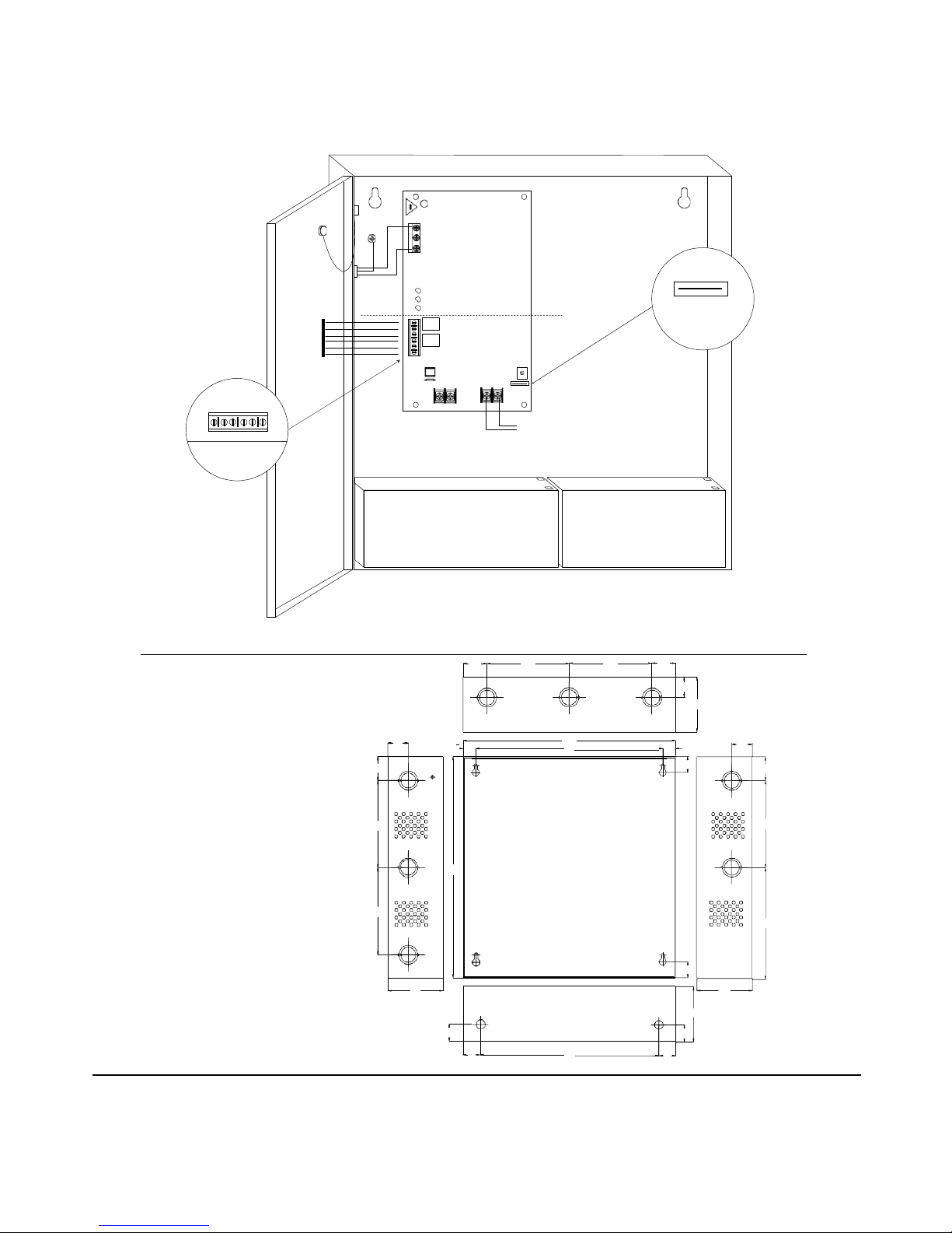
Installation Instructions:
The unit should be installed in accordance with article 760 of The National Electrical Code as well as NFPA 72 and all
applicable Local Codes.
1.
Mount unit in the desired location. Mark and predrill holes in the wall to line up with the top two keyholes in the
enclosure. Install two upper fasteners and screws in the wall with the screw heads protruding. Place the enclosure’s
upper keyholes over the two upper screws; level and secure. Mark the position of the lower two holes. Remove the
enclosure. Drill the lower holes and install two fasteners. Place the enclosure’s upper keyholes over the two upper
screws. Install the two lower screws and make sure to tighten all screws (Enclosure Dimensions, pg. 4).
2.
The power supply is pre-wired to the ground (chassis). Connect main incoming ground to the provided green
grounding conductor lead. Connect unswitched AC power (115VAC / 60 Hz) to the terminals marked [L, N] (Fig.
1, pg. 4). Use 14 AWG or larger for all power connections (Battery, DC output, AC input). Use 22 AWG to 18
AWG for power-limited circuits (AC Fail/Low Battery reporting).
Keep power-limited wiring separate from non power-limited wiring (115VAC / 60Hz Input, DC Output,
Battery Wires). Minimum 0.25” spacing must be provided.
CAUTION: Do not touch exposed metal parts. Shut branch circuit power before installing or servicing equipment.
There are no user serviceable parts inside. Refer installation and servicing to qualified service personnel.
For Fire Alarm applications the outputs are “Special Applications” only.
3.
Set the unit to the desired DC output voltage by setting SW1 (Fig. 1a, pg. 4) to the appropriate position
(Power Supply Voltage Output Selections Chart, pg. 3).
4.
Measure output voltage before connecting any devices to ensure proper operation. Improper or high voltage will
damage these devices. When servicing the unit, AC mains should be removed.
5.
Connect devices to be powered to terminals marked [+ DC -], carefully observing correct polarity (Fig. 1, pg. 4).
6.
For Access Control applications batteries are optional. When batteries are not used, a loss of AC will result in the
loss of output voltage. When the use of stand-by batteries is desired, they must be lead acid or gel type.
7.
Connect appropriate signaling notification devices to the terminals marked [AC FAIL & BAT FAIL] (Fig. 1, pg. 4)
supervisory relay outputs.
Note: When used in fire alarm or access control applications, “AC Fail” relay should be utilized
to visually indicate that AC power is on. To delay report for 6 hours cut “AC Delay” jumper (Fig. 1, pg. 4).
8.
Please ensure that the cover is secured with the provided Key Lock.
Altro nix
Corp .

- 3 -
Power Supply Output Specifications:
Output
Switch Position
12VDC
SW1 - CLOSED (Fig. 1a, pg. 4)
24VDC
SW1 - OPEN (Fig. 1a, pg. 4)
Stand-by Specifications (total current shown):
Output 4 hr. of Stand-by &
5 Minutes of Alarm
24 hr. of Stand-by &
5 Minutes of Alarm
60 hr. of Stand-by &
5 Minutes of Alarm
12VDC / 40AH Battery Stand-by = 6.0 amp
Alarm = 6.0 amp
Stand-by = 1.0 amp
Alarm = 6.0 amp
Stand-by = 300mA
Alarm = 6.0 amp
24VDC / 12AH Battery -------- Stand-by = 200mA
Alarm = 6.0 amp --------
24VDC / 40AH Battery Stand-by = 6.0 amp
Alarm = 6.0 amp
Stand-by = 1.0 amp
Alarm = 6.0 amp
Stand-by = 300mA
Alarm = 6.0 amp
LED Diagnostics:
Red (DC)
Green (AC) Red (BAT) Status
ON ON ON Normal operating condition.
ON OFF ON Loss of AC. Stand-by battery supplying power.
OFF ON OFF No DC output. Battery Trouble
OFF OFF OFF Loss of AC. Discharged or no stand-by battery. No DC output.
ON ON OFF Battery missing / Low battery.
Terminal Identification:
Terminal
Legend Function/Description
L, G, N Connect 115VAC 60 Hz. to these terminals: L to hot, N to Neutral. Do not use the [G] terminal.
+ DC --- 12VDC or 24VDC @ 6 amp continuous non power-limited output.
AC Fail
NC, C, NO
Indicates loss of AC power, e.g. connect to audible device or alarm panel. Relay normally energized
when AC power is present. Contact rating 1 amp @ 28VDC. AC or brownout fail is reported within 1
minute of the event. To delay reporting for up to 6 hrs., cut “AC delay” jumper and reset power to unit.
Bat Fail
NC, C, NO
Indicates low battery condition, e.g. connect to alarm panel. Relay normally energized when DC power
is present. Contact rating 1 amp @ 28VDC. Low battery conditions will report approximately 21VDC
(24VDC output setting) or approximately 10.5VDC (12VDC output setting).
Battery presence detection will report approximately 1 minute after battery remains undetected
(missing or removed).
+ BAT --- Stand-by battery connections. Maximum charge current 0.7 amp.
Use 14 AWG or larger for all power connections.
Wiring:
Note: Take care to keep power-limited circuits separate from non power-limited wiring (115VAC, Battery).
Maintenance:
Unit should be tested at least once a year for the proper operation as follows:
Output Voltage Test: Under normal load conditions the DC output voltage should be checked for proper voltage level
(Power Supply Voltage Output Specifications Chart, pg. 3).
Battery Test: Under normal load conditions check that the battery is fully charged, check specified voltage both at the
battery terminal and at the board terminals marked [+ BAT –] to ensure that there is no break in the battery
connection wires.
Note: Maximum charging current under discharges is 0.7 amp.
Note: Expected battery life is 5 years; however, it is recommended changing batteries in 4 years or less if needed.

- 4 -
AC DC BAT
BAT FAIL NC C NO NC C NO AC FAIL
Fig. 1
CAUTION: De-energize unit prior to servicing. For continued protection against
risk of electric shock and fire hazard replace fuse with the same type and rating.
Do not expose to rain or moisture.
Door Green
Wire
Strap
(from
Enclosure
to Door)
Lead
Do Not Touch
Exposed Metal Parts
Fig. 1a
Fig. 1b
Battery & AC
Supervision
Circuit
(power-limited)
115VAC
power mains
non power-
limited
Class 1 24V - OPEN
12V - CLOSED
OPEN - 24V
CLOSED - 12V
+ BAT --- + DC ---
BAT FAIL NO C NC NO C NC AC FAIL
Battery & AC Supervision
Circuit
(power-limited)
Battery conn ection
(non power-lim ited)
DC Output to devices
(non power-limited)
12VDC Rechargeable Battery
(optional)
CAUTION: Optional rechargeable stand-by batteries must match
the power supply output voltage setting.
Keep power-limited wiring separate from non power-limited.
Use minimum 0.25" spacing.
Enclosure Dimensions (H x W x D):
13.5” x 13” x 3.25” (342.9mm x 330.2mm x 82.55mm)
* The door is included
12.5”
1.20”
(31mm)
1.40”
(36mm)
5.10”
(130mm)
5.10”
(130mm)
3.25”
(83mm)
(25mm)
(267mm)
(25mm)
Hochiki America Corp.
7051 Village Drive, Suite 100, Buena Park, CA 90621-2268, 714-522-2246, Fax: 714-690-7890, www.hochiki.com
IIFN-600ULX G02N
1.40”
(36mm)
4.85”
(123 mm)
4.85”
(123 mm)
1.40”
(36mm)
1.20”
(31mm)
3.25”
(83mm)
0.75”
(19mm)
(318mm)
0.75”
1.20”
(31mm)
(279mm)
11.0”
(19mm)
0.9375”
(24mm)
1.40”
(36mm)
5.10”
(130 mm)
13.0”
(330 mm)
6.5625”
(167 mm)
0.9375”
(24mm)
3.25”
(83mm)
3.25”
(83mm)
1.0”
(25mm)
1.0”
(25mm)
1.0”
10.5”
1.0”
12VDC Rechargeable Battery
(optional)
SW1
5A 2 50V
L G N
Table of contents
Other Hochiki America Corporation Power Supply manuals