INSTALLATION AND MAINTENANCE INSTRUCTIONS
Hochiki America Corporation
7051 Village Drive, Suite 100
Buena Park, CA 90621-2268
DWG # HA-06-043, Rev 08/22
PAGE 1 of 2
PART # 1700-09985
Intelligent Addressable Detectors and Bases
Operating Temperature Range
Listed Ambient Temperature Range
Storage Temperature Range
Mounting Box Compatibility
Refer to the Technical Bulletin HA-06-433 (accessible at www.Hochiki.com) for the following UL listed compatible
detectors. Connect these detectors only to a listed-compatible control panel. Refer to the control panel installation
manual for additional instructions. Smoke detectors are not to be used with detector guards unless the combination has
been evaluated and found suitable for that purpose:
ALN-V Smoke Detector
ALO-V Smoke Detector
ACC-V Smoke and Heat Detector
ACD-V Smoke, Heat, and CO Detector
ATJ-EA Fixed Temperature and Rate of Rise Detector
Detectors must be installed and maintained in accordance with applicable NFPA standards, local codes and any authority
having jurisdiction. Refer to NFPA 72 "National Fire Alarm and Signaling Code" and to NFPA 720 "Standard for
Installation of Carbon Monoxide Detection and Warning Equipment" for installation guidelines and testing procedures.
Smoke detectors should be tested in accordance with NFPA 72, section on "Inspection, Testing and Maintenance".
NFPA 72 and 720 audible requirements for sleeping areas can be met with Hochiki America's ASBL7 Low Frequency
Sounder Base. Hochiki America recommends ASBL7 use with our CO detectors for all installations.
Seal conduit openings in the electrical box with 3M Weatherban #606 nonflammable sealing compound (or equivalent)
to reduce the stack effect. Attach the detector to the base by turning the detector clockwise until it stops.
*
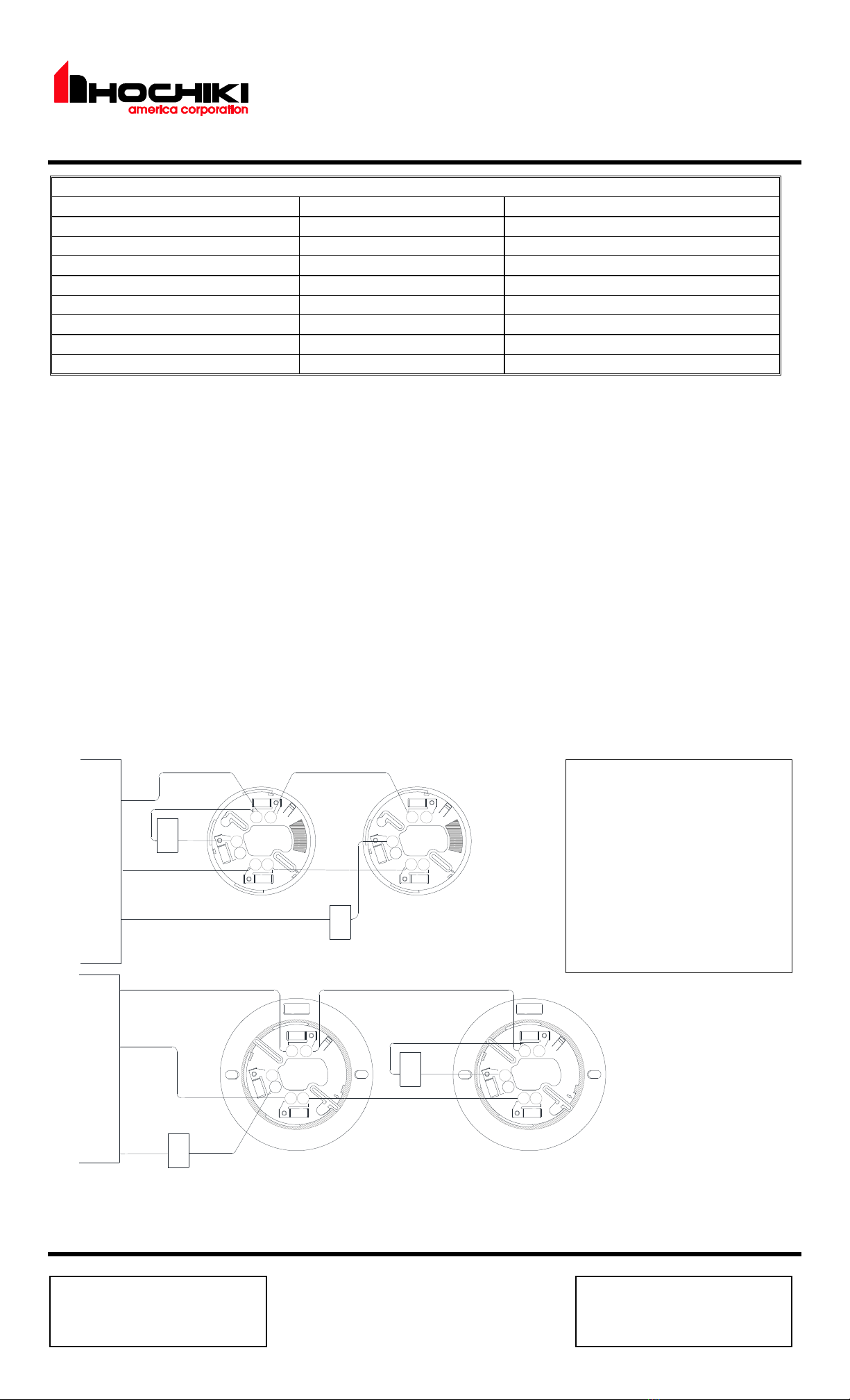
YBN-NSA-47 WIRING CONNECTION
LED
*
LED
( - )
( + )
U.L.
LISTED
COMPATIBILE
DCP
LOOP
LIMITED
SUPPLY
POWER
LISTED
U.L.
( + )
( + )
( - )
U.L.
LISTED
COMPATIBILE
CONTROL
PANEL
LIMITED
SUPPLY
POWER
LISTED
U.L.
( + )
2
1
3
4
65
HSB-NSA-67 WIRING CONNECTION
* OPTIONAL WIRING CONFIGURATIONS FOR REMOTE
ALARM INDICATOR LED, 9.6mA max output
LED
(RED) (BLACK)
RAI-LED
(RED)
RAI-LED
(RED) (BLACK)
RAI-LED
(RED)
RAI-LED
(BLACK)
(BLACK)
LED
2
1
3
4
65
2
1
3
4
65
2
1
3
4
65
ATTENTION
TOTAL WIRING RESISTANCE
LESS THAN 50Ω(14-18AWG)
ADDRESS DETECTORS PRIOR TO
INSTALLATION,
REFER TO TECHNICAL BULLETIN
HA-06-433.
REMOVE THE DUST COVER
PRIOR TO OPERATION.


