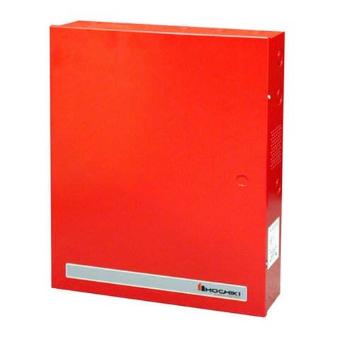
Hochiki HE-PSU Installation instructions

Hochiki Europe (UK) Ltd – HE-PSU(1.25) Power Supply Installation Manual
Page 1 of 4 2-3-0-995/ISS1/OCT07
HE-PSU(1.25)
Power Supply &
Battery Charger
Installation,
Commissioning
& Operating Manual

Hochiki Europe (UK) Ltd – HE-PSU(1.25) Power Supply Installation Manual
Page 2 of 4 2-3-0-995/ISS1/OCT07
CONTENTS
1.0 INSTALLATION......................................................................................................2
1.1 Safety ................................................................................................................. 2
1.2 General...............................................................................................................2
1.3 Mounting the Cabinet..........................................................................................2
2.0 COMMISSIONING .................................................................................................3
2.1 Mains Connection............................................................................................... 3
2.2 Load Connection.................................................................................................3
2.3 Fault/Healthy Connection ................................................................................... 3
2.4 Battery Connection.............................................................................................3
3.0 OPERATION & MAINTENANCE............................................................................3
3.1 Specifications.................................................................................................. 4
1.0 INSTALLATION
1.1 Safety
IMPORTANT - READ THIS SECTION FIRST!
Suppliers of articles for use at work are required under section 6 of the Health and Safety at Work Act
1974 to ensure as reasonably as is practical that the article will be safe and without risk to health when
properly used. An article is not regarded as properly used if it is used "without regard to any relevant
information or advice" relating to its use made available by the supplier.
This product should be installed, commissioned and maintained by or under the supervision of competent
persons according to good engineering practice and:-
IEE regulations for the electrical equipment of buildings.
Codes of practice.
Statutory requirements.
Any instructions specifically advised by the manufacturer.
According to the provisions of the act you are therefore requested to take such steps as are necessary
to ensure that any appropriate information about this product is made available by you to anyone
concerned with its use.
This equipment is designed to be operated from 220-240V AC mains supplies and is of class I
construction. As such it must be connected to a protective earthing conductor in the fixed wiring of the
installation.
Failure to ensure that all conductive accessible parts of this equipment are adequately bonded to the
protective earth will render the equipment unsafe.
1.2 General
Installation of the panel should only be carried out by qualified personnel. The electronic components
within the panel can be damaged by static charge. Suitable precautions must be taken when handling
circuit boards. Never insert or remove boards or components with power on.
1.3 Mounting the Cabinet
The site chosen for the location of the panel should be clean and dry, and not subject to shock or
vibration. The temperature should be in the range -5° to +50°C, and the humidity should not exceed
95%.
Using the cabinet as a template, mark the position of the four fixing holes, ensuring that the wall is flat at
the chosen location, drill and plug the wall and fix the cabinet using the four fixings cabling.

Hochiki Europe (UK) Ltd – HE-PSU(1.25) Power Supply Installation Manual
Page 3 of 4 2-3-0-995/ISS1/OCT07
Suitable cables should be brought into the cabinet using the knockouts provided, making sure that tails are
long enough to reach the relevant terminals. The screen or drain wire should be bonded to earth at one
location only, it should be continuous throughout the circuit. Terminals will accept one single or
stranded conductor up to 2.5 mm2.
2.0 COMMISSIONING
2.1 Mains Connection
The mains is connected to the PSU via a fused terminal block marked with live, neutral and earth
symbols. It is imperative that the equipment is soundly earthed and this connection should be made
and checked first.
Following connection of the live and neutral cables and with no other connections made, the unit should be
powered and the battery output measured at around 28 volts DC.
2.2 Load Connection
Terminals are provided for connection to the load and are marked + and -. The voltage at these
terminals under normal conditions (i.e. off load) should be around 28.5 to 29 volts. With the mains
power off, connect the load cables.
Double check the load connection for correct polarity before switching on mains. After switching on
mains check the voltage at the load for correct polarity.
Do not connect or disconnect the wiring to the load terminals with mains or battery power on.
2.3 Fault/Healthy Connection
Switched -VE outputs are available for signalling of power fault and power healthy indication marked PO
(power on) and PF (power fault). Under normal circumstances (mains and battery connected and fuses
intact) the -VE appears at the PO terminal.
Failure of the mains or battery supply will transfer the -VE to the PF terminal.
A volt free changeover contact is also available for fault/healthy signalling which can be used to switch
other voltages or signals
2.4 Battery Connection
An output is provided via flying leads with 0.25 inch spade receptacles for connection to sealed lead acid
rechargeable batteries. Normally two 12 volt batteries are connected in series and then to the charger.
Before connecting the batteries measure the output voltage on the leads. It should be 28 volts ±0.1
volt. If the voltage differs from this, adjust it to the correct level using the control on the PCB (this may
vary from the factory setting due to variations in mains supply voltage).
It is very important that the correct polarity is observed before connecting the batteries as the wrong
polarity connection will blow the charging fuse and may damage the unit.
With the batteries connected and the mains on the fault contact should show continuity between the “C”
and “NC” terminals. With the battery on mains disconnected the fault contact should show continuity
between the “C” and “NO” terminals.
With the battery connected switch off the mains and ensure that a supply is present at the load terminals.
3.0 OPERATION & MAINTENANCE
Under normal circumstances the power supply requires no attention and will transfer automatically to
battery supply in the event of a mains failure. Periodic checks should be made however to ensure
maximum life of the sealed lead acid battery.
To do this, disconnect the battery and using a calibrated voltmeter ensure that the voltage on the
battery leads is 28 volts ±0.1 volt. Adjust this if necessary using the control on the PCB.

Hochiki Europe (UK) Ltd – HE-PSU(1.25) Power Supply Installation Manual
Page 4 of 4 2-3-0-995/ISS1/OCT07
Disconnect the mains supply and ensure that the fault contact operates and that the battery can supply
the load.
3.1 Specifications
Frequency - 50/60 HZ
Input voltage range - 220 to 240 V AC
Battery charge voltage - 28 V DC
Load voltage - 29 V DC (nom)
Max continuous load - 625mA
Construction - Class I
Terminal capacity - 2.5 mm2
Fault contact rating - 1 amp 3O V DC
Battery type - Sealed lead acid
Hochiki Europe (UK) Ltd
Grosvenor Road, Gillingham Business Park,
Gillingham, Kent, ME8 0SA, England
Telephone: +44(0)1634 260133 Facsimile: +44(0)1634 260132
Email: sales@hochikieurope.com
Web: www.hochikieurope.com
Hochiki Europe (UK) Ltd. reserves the right to alter the specification of its products from time to time without notice. Although
every effort has been made to ensure the accuracy of the information contained within this document it is not warranted or
represented by Hochiki Europe (UK) Ltd. to be a complete and up-to-date description. Please check our web site for the
latest version of this document.
Table of contents
Other Hochiki Power Supply manuals