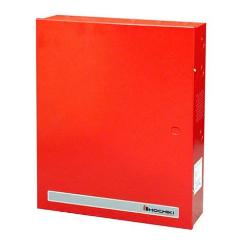
Hochiki HE-PSU(4.0) Guide

Hochiki Europe (UK) Ltd – HE-PSU(4.0) Installation Manual
Page 1 of 10 2-3-0-997/ISS1/OCT07
HE-PSU(4.0)
Power Supply &
Battery Charger
Installation,
Commissioning
& Operating Manual

Hochiki Europe (UK) Ltd – HE-PSU(4.0) Installation Manual
Page 2 of 10 2-3-0-997/ISS1/OCT07
CONTENTS
1. GENERAL........................................................................................................................2
2. POWER REQUIREMENTS .............................................................................................2
2.1 HE-PSU(4.0) Input/Output Electrical Ratings.............................................................2
2.2 Fuse Ratings..............................................................................................................3
2.3 Batteries.....................................................................................................................3
3. INSTALLATION...............................................................................................................3
3.1 Environmental Considerations....................................................................................3
3.2 Mounting ....................................................................................................................3
3.3 Connecting to the Input..............................................................................................4
3.4 Connecting to the Outputs..........................................................................................4
3.4.1 Load Connections (Terminal Block).....................................................................4
3.4.2 Load Connections (Ribbon Cable).......................................................................4
3.4.3 Battery Connections ............................................................................................5
4. COMMISSIONING...........................................................................................................6
5. MAINTENANCE...............................................................................................................6
6. MOUNTING.....................................................................................................................8
7. WIRING ...........................................................................................................................8
8. CABLE TERMINATION ...................................................................................................9
9. OPERATING INSTRUCTIONS......................................................................................10
1. GENERAL
The HE-PSU(4.0) is a combined power supply and battery charger designed to be used for fire alarm control
and indicating equipment complying with EN54-2 and EN54-4.
2. POWER REQUIREMENTS
The HE-PSU(4.0) requires a mains power supply of 230V AC. The maximum input current is 2 Amps.
Mains frequency 50Hz.
2.1 HE-PSU(4.0) Input/Output Electrical Ratings
Input – 230V AC
Load output - 19V DC min (battery at minimum), 30 V DC max (mains on) max current 2.5 Amps + 1.5A
for battery charging.
Maximum ripple 800 millivolts
Battery charging output - 26.4 VDC (at 40°C) 28.9 V DC (at -5°C) 1.5 Amps.
Fault signals - switched negative open collector (with respect to load positive) current limited 100mA max.
Mainsfail
Battery disconnected (Low battery shut off voltage - 19 V (+/- 1 volt))
Battery low (Low battery warning voltage - 21 V (+/- 1 volt))
Earthfault
Charger fault (high output to battery)
Fail safe (any one of the above)
These outputs are protected against short circuits.

Hochiki Europe (UK) Ltd – HE-PSU(4.0) Installation Manual
Page 3 of 10 2-3-0-997/ISS1/OCT07
2.2 Fuse Ratings
Input fuse - T2A L250V. Replace only with a fuse of the same type.
Load fuse - self-resetting polyfuse 4 Amp rated. (Not replaceable).
RPSM fuse- Glass antisurge fuse 4A; BS4265
2.3 Batteries
Rechargeable, sealed lead acid Yuasa NP or equivalent. Maximum capacity 17 Ah, minimum capacity 7Ah.
Maximum current consumption from battery – 4A.
Quiescent current in mains failure mode - 30 mA.
3. INSTALLATION
This product should be installed, commissioned and maintained by trained service personnel in accordance
with the following:
(i) IEE regulations for electrical equipment in buildings
(ii) Codes of practice
Statutory requirements
Any instructions specifically advised by the manufacturer
3.1 Environmental Considerations
The operating temperature range should not exceed -5°C to +40°C (±2°).
Humidity levels should not exceed 96% (non-condensing).
3.2 Mounting
The HE-PSU(4.0) is supplied as an enclosure in portrait orientation with the terminal block to the left. The
requirements of EN60950 regarding creepage, clearance, marking and segregation must be taken into
consideration and the power supply should remain accessible for fuse replacement and to access screw
terminal connections.
The equipment is of Class1 construction so must be permanently and reliably connected to the fixed earth of
the installation.
The primary earth of the end use application must be permanently marked with the protective earth symbol
(IEC415 No. 5017). A suitable primary disconnecting device must be provided in the end use application.
Battery and load connections must be considered for connection to SELV (safety extra low voltage) circuits
only.
The maximum leakage current of the completed and installed equipment must not exceed 3.5mA..

Hochiki Europe (UK) Ltd – HE-PSU(4.0) Installation Manual
Page 4 of 10 2-3-0-997/ISS1/OCT07
3.3 Connecting to the Input
Do not connect a mains supply unless the supply voltage matches that shown on the rating plate.
Pass the incoming live and neutral of the mains cable through the ferrite core at the top of the enclosure
looping it back so that there are two turns through it.
Connect the Live and Neutral to the circuit board as indicated on the PCB on the next page.
Connect earth to the earth terminal at the top of the enclosure.
Note: A minimum cable size of 0.75mm must be used. Maximum cable size is 2.5mm².
Ensure that all wires are fitted into the terminals without any exposed lengths or strands which may give rise
to exposure to electrical shock.
This equipment is designed to be operated from 230V 50Hz mains supplies and is of class 1 construction.
As such it must be connected to a protective earthing conductor in the fixed wiring of the installation and a
readily accessible double pole disconnect device meeting the requirements of EN60950/IEC950 which
disconnects live and neutral simultaneously shall be incorporated in the fixed wiring as close to the unit as is
practical.
If the earth terminal is the primary earth of the end use application then apply the earth symbol (IEC415
No.5017) next to this terminal. Ensure that all screws in the earth terminal block (including those that are not
used) are tightened during installation.
3.4 Connecting to the Outputs
3.4.1 Load Connections (Terminal Block)
Four terminals are provided for connection of the load. Two + terminals and two - terminals.
The load should be connected using wire rated for at least 4 Amps.
Care must be taken to connect the polarity of the load the correct way around, + on the PSU to + on the load
and - on the PSU to - on the load.
Note: Maximum cable size is 2.5mm
3.4.2 Load Connections (Ribbon Cable)
An alternative method of connecting to the power supply is via a 14-way ribbon cable.
A standard latching ribbon cable header is provided on the board, which may be used to connect to the load,
and fault signals, which are provided on the terminal block. (See below.)

Hochiki Europe (UK) Ltd – HE-PSU(4.0) Installation Manual
Page 5 of 10 2-3-0-997/ISS1/OCT07
3.4.3 Battery Connections
Batteries of even very small capacity are capable of delivering very high currents which can cause fire or
injury. Battery connections must therefore be done using extreme caution.
As supplied, the HE-PSU(4.0) has battery leads already wired to the battery terminals on the circuit board.
These leads are coloured red for + and black for - .

Hochiki Europe (UK) Ltd – HE-PSU(4.0) Installation Manual
Page 6 of 10 2-3-0-997/ISS1/OCT07
As this is a 24-Volt system, there will be two 12 volt batteries which need to be connected in series. This is
done using the jumper link provided.
To optimise the service life of the batteries, the battery charger output voltage varies with temperature. To
enable optimum temperature compensation, the flying lead thermistor should be attached to one of the
batteries.
4. COMMISSIONING
Once all connections have been made and checked for safety, switch on the mains power. The load should
now be supplied with power and the batteries should be taking a charge.
Check that the load is being supplied by observing the power on lamp on the load (control and indicating
equipment). Remove the mains power and ensure that the batteries continue to supply power to the load.
With the mains removed, a negative signal should appear at the terminal MF (mains failed) and the MF LED
should light after about 90 seconds. This can be checked by connecting a voltmeter between load + and
terminal MF.
Switch the mains back on and disconnect the battery. The load should continue to operate and a negative
signal should appear at the terminal BD (battery disconnected) and the BD LED should light after about 30
seconds. Check this with a voltmeter between load + and the terminal BD.
Now connect the load + terminal to earth using a piece of wire. Within 30 seconds a negative should appear
at the terminal EF (earth fault) and the EF LED should light.
Disconnect the load + from earth and connect the load - to earth. Within 30 seconds a negative should
appear at the terminal EF and the EF LED should light.
With the battery disconnected, measure the output voltage from the power supply battery terminals with a
calibrated digital voltmeter. The voltage should be within 0.2 Volts of the value indicated on the
voltage/temperature graph (see opposite page.).
This completes the basic commissioning checks.
5. MAINTENANCE
THIS EQUIPMENT CONTAINS NO USER SERVICABLE PARTS
The power supply requires no maintenance; however, sealed lead acid batteries have a limited lifespan and
should be checked periodically in accordance with the manufacturer’s recommendations.
It is advisable to check the battery charger output voltage once per year to check that the output has not
drifted.

Hochiki Europe (UK) Ltd – HE-PSU(4.0) Installation Manual
Page 7 of 10 2-3-0-997/ISS1/OCT07
To do this the batteries should be disconnected and the output voltage measured with a calibrated digital
voltmeter. The voltage should be within 0.2 volts of the indicated voltage on the voltage/temperature graph
below.

Hochiki Europe (UK) Ltd – HE-PSU(4.0) Installation Manual
Page 8 of 10 2-3-0-997/ISS1/OCT07
6. MOUNTING
The power supply should be mounted on a dry, flat surface.
Screws or bolts of a minimum of 5mm diameter must be used to mount the enclosure in all four mounting
positions. The mounting method must be suitable to support 60Kg (3 times the weight of the unit with
maximum sized batteries fitted).
It should be positioned in an accessible position as agreed with the end user.
The power supply should not be mounted in another enclosure or near sources of excessive heat.
Cables should be connected using suitable cable glands (see section 8) fitted to the knockouts provided. If
additional cable entry points are required, all swarf and debris caused by drilling of additional cable entries
must be cleared before power is applied.
7. WIRING
The HE-PSU(4.0) power supply is capable of housing up to 17Ah sealed lead acid batteries.
To comply with the requirements of EN54-4 there must be two transmission paths from the power supply to
the control panel in order that a short circuit in one transmission path will enable the control panel to be
supplied with power from the other.
This is facilitated by the RPSM-1 PCB which is mounted in the enclosure. Individual fault outputs are
provided on the power supply. A common fault open collector output rated at 100 milliamps maximum is
provided on the RPSM-1 board.
+
+
SERIALNO.
R15
C
8
C
3
C12
C15
C26
C21
R
1
R
2
R
6
R
9
R
8
R20
R
7
VDR
1
OPT
1
REG
2
TR1
Z5
Z6
TR2
C18
C19 C23 R16
R18
R19R21
R22
R24
R25
R26R27
R31
R37
R38
R39
R40
R41
C
4C
5
C28
R44
R46
R45
R36
R43
R49
R47
R50
R48
R51
R13
C30
R55
R54 R29
D9
C1
R56
D5
R42
R58
R52
R57
C34
R34
C35
+
-
+
-
paths to remote
FERRITE
LIVE
EARTH
NEUTRAL
LOOP INCOMING MAINS WIRES SUCH
THAT THEY PASS TWICE THROUGH
CENTRE OF FERRITE CORE
MAXIMUM CABLE RESISTANCE
0.5 OHMS PER CORE
TO EARTH BLOCK ON
TOP EDGE OF
ENCLOSURE
FROM EARTH BLOCK ON
TOP EDGE OF
ENCLOSURE
LED1LED2
F1 F2
X2
X1
D1
D2
D3
D4
D5
D6 D7
D8
D9
R1
R2
R3
R4
RL1 RL2
X3
F3
4A 4A
A
FLT
B
FLT
ISS.A
RPSM-1
+
-
SUPPLY
ASUPPLY
B
+
-
FAULT
-VE
Power
transmission
control panel
panel
Common fault
signal to control
extended beyond the enclosure
Individual fault signals
( for internal use only. Not to be

Hochiki Europe (UK) Ltd – HE-PSU(4.0) Installation Manual
Page 9 of 10 2-3-0-997/ISS1/OCT07
8. CABLE TERMINATION
All cable entries to the enclosure must be via Pirelli AXT20SK Cable terminating kits or equivalent.

Hochiki Europe (UK) Ltd – HE-PSU(4.0) Installation Manual
Page 10 of 10 2-3-0-997/ISS1/OCT07
9. OPERATING INSTRUCTIONS
The HE-PSU(4.0) is intended for use only as Power Supply Equipment for 24V DC fire detection and alarm
systems conforming to EN54-2 and EN54-4.
All mounting, installation, commissioning and maintenance should be carried out strictly in accordance with
the instructions contained in the manual.
Under normal operating conditions, none of the LED indicators should be lit and there should be no output
on any of the fault output terminals.
Fault conditions are identified by the printed legends on the black ventilated cover of the PSU within the
enclosure and relate to the on-board LED indicators.
The switched negative fault outputs may be used to operate 24VDC rated relays or indicators up to the
current limit of 100 milliamps per output. The reference voltage for the switched negative outputs is the load
positive.
Hochiki Europe (UK) Ltd
Grosvenor Road, Gillingham Business Park,
Gillingham, Kent, ME8 0SA, England
Telephone: +44(0)1634 260133 Facsimile: +44(0)1634 260132
Email: sales@hochikieurope.com
Web: www.hochikieurope.com
Hochiki Europe (UK) Ltd. reserves the right to alter the specification of its products from time to time without notice. Although every
effort has been made to ensure the accuracy of the information contained within this document it is not warranted or represented by
Hochiki Europe (UK) Ltd. to be a complete and up-to-date description. Please check our web site for the latest version of this
document.
Table of contents
Other Hochiki Power Supply manuals