©/TM 2023 UnityLab Corp. All rights reserved. | 21
1.0 INTRODUCTION
This manual contains the installation, operation and maintenance instructions,
troubleshooting guide, repair parts illustrations and lists for the Hoffman Electric
Steam Generators. The Steam Generators are designed and manufactured
with constant attention to quality, performance, operator safety and energy
efciency. With proper installation, operation and maintenance, the Hoffman
Electric Steam Generator will last a lifetime.
The Steam Generators are composed of a pressure vessel, a safety valve, piping,
a heating element, controls and the enclosure.
The pressure vessel is manufactured from high strength steel or cast bronze.
It is rated at 100 pounds per square inch of steam pressure. The vessel, safety
valve and piping have been designed to the standards set forth in the American
Society of Mechanical Engineers Boiler and Pressure Vessel Code. It meets or
exceeds their requirements for safety. Many Steam Generator assemblies are UL
and/or CUL listed. Consult your Hoffman distributor for their identication.
The Heating Element is a ange mounted immersion element. Immersion
elements are the most energy efcient heating elements available. This is due
to the element making contact with the working uid (water), transferring all the
energy required for heating water into steam.
Some electric steam generator models use a thermostat controller to regulate
the steam pressure. The controller senses the temperature and regulates the
current to the heating element to provide the desired output. Larger generators
are regulated with pressure switch controllers.
Steam pressure and temperature are related. The higher the steam pressure, the
higher the temperature. For a listing of pressures and corresponding temperatures
see Chapter 6, Table 6.1.1.
Hoffman also offers a wide variety of options for the steam generators. For a
listing of the options available, please contact your Hoffman Distributor.
1.1 INTENDED USE
The generators listed in this manual are intended for small steam usage
requirements. They may be used for jewelry steam cleaning, dental lab steam
cleaning, auto trim, furrier glazing of garments, or for use with steam irons, etc.
The units are capable of producing high-pressure steam. They should not be
used for applications that require low-pressure steam unless provisions are
made to limit the steam pressure (i.e. autoclaves, steam bath applications, etc.).
The machines are not intended for space heating purposes.
1.2 REGISTRATION WITH LOCAL JURISDICTION
The steam generator may need to be registered with your local or state
government. Check with your municipality for requirements.
Table of Contents
1.0 INTRODUCTION .................................................................................... 2
1.1 INTENDED USE ...........................................................................................................................2
1.2 REGISTRATION WITH LOCAL JURISDICTION .....................................................................2
1.3 PRELIMINARY DELIVERY INSPECTION ..................................................................................3
1.4 WARRANTY ACTIVATION ......................................................................................................3
1.5 SAFETY AND PRECAUTIONS..................................................................................................3
1.5.1 SAFETY NOMENCLATURE.................................................................................................3
1.5.2 SAFETY FEATURES.............................................................................................................3
1.5.3 SAFETY SUMMARY........................................................................................................... 4
2.0 INSTALLATION ..................................................................................... 5
3.0 OPERATING INSTRUCTIONS ................................................................ 6
4.0 MAINTENANCE .................................................................................... 7
4.1 CLEANING THE BOILER..........................................................................................................7
4.2 CLEANING THE SIGHT GLASS..............................................................................................7
4.3 BLOWING DOWN THE BOILER .............................................................................................7
4.4 CLEANING THE STRAINER....................................................................................................7
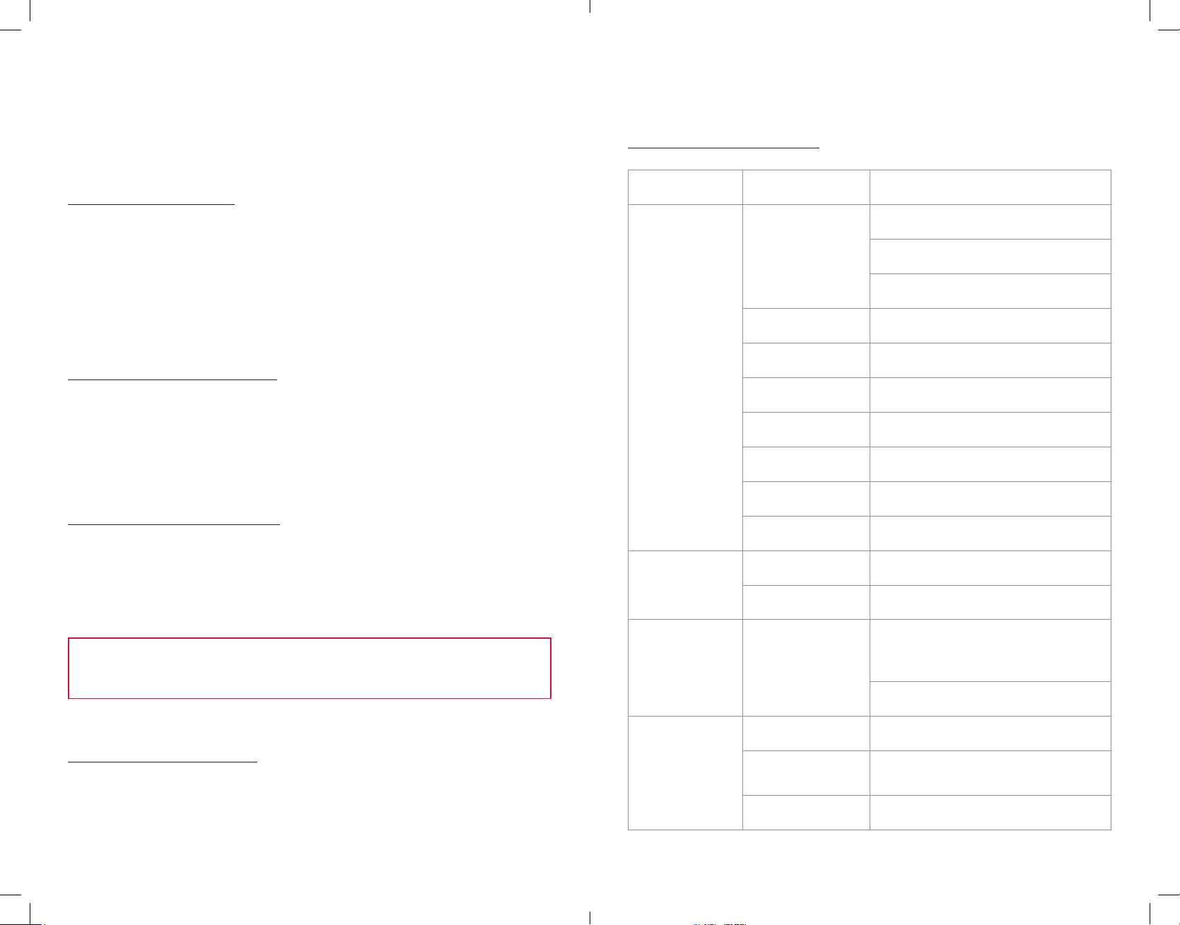
5.0 TROUBLESHOOTING & SERVICING...................................................... 8
5.1 TROUBLESHOOTING TABLE .................................................................................................. 8
5.2 ADJUSTING THE STEAM PRESSURE ..................................................................................10
5.2.1 THERMOSTAT CONTROL ...............................................................................................10
5.3 REPLACING THE THERMOSTAT
5.4 REPLACING THE GAUGE SIGHT GLASS............................................................................11
5.5 REPLACING THE HEATING ELEMENT
5.6 REPLACING THE LOW WATER SWITCH........................................................................... 12
5.7 REPLACING THE ELECTRIC FOOT SWITCH AND/OR CORD........................................ 12
5.8 REPLACING THE ON/OFF SWITCH................................................................................... 13
5.9 CLEANING THE ELECTRIC SOLENOID VALVE..................................................................14
5.10 REPLACING THE ELECTRIC SOLENOID VALVE ...............................................................14
6.0 TABLES ................................................................................................15
6.1 PRESSURE VS. TEMPERATURE............................................................................................15
6.2 ELECTRICAL SPECIFICATIONS ..........................................................................................15
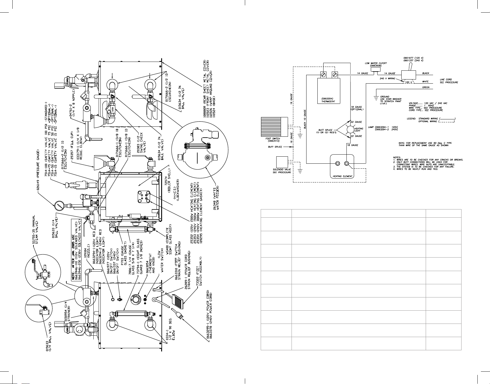
7.0 DRAWINGS & PARTS LIST ..................................................................16