Hofmann FPA12144 User manual

4 POST
MODEL
MODEL
:
FPA12144 (Alignment) / FPF12144 (Service)
(12000 LB.)
READ and SAVE THIS
INSTRUCTION MANUAL
MAY 2012 REV.- 6-2616

2 of 44
1.0 OWNER/EMPLOYEROBLIGATIONS
1. TheOwner/Employershallensurethatliftoperatorsarequalifiedandthattheyare
trainedinthesafeuseandoperationoftheliftusingthemanufacturer’soperating
instructions;ALI/SM93‐1,ALILiftingitRightsafetymanual;ALI/ST‐90ALISafetyTips
card;ANSI/ALIALOIM‐2008,AmericanNationalStandardforAutomotiveLifts‐Safety
RequirementsforOperation,InspectionandMaintenance,AppendixA(Operator
TrainingLog);ALI/WLSeries,ALIUniformWarningLabelDecals/Placards;andinthecase
offrameengaginglifts,ALI/LP‐GUIDE,VehicleLiftingPoints/QuickReferenceGuidefor
FrameEngagingLifts.
2. TheOwner/Employershallestablishprocedurestoperiodicallyinspecttheliftin
accordancewiththeliftmanufacturer’sinstructionsorANSI/ALIALOIM‐2008,American
NationalStandardforAutomotiveLifts‐SafetyRequirementsforOperation,Inspection
andMaintenance,AppendixBandAppendixesCthroughF;andtheEmployershall
ensurethattheliftinspectorsarequalifiedandthattheyareadequatelytrainedinthe
inspectionofthelift.
3. TheOwner/Employershallestablishprocedurestoperiodicallymaintaintheliftin
accordancewiththeliftmanufacturer’sinstructionsorANSI/ALIALOIM‐2008,American
NationalStandardforAutomotiveLifts‐SafetyRequirementsforOperation,Inspection
andMaintenance,AppendixG(PlannedMaintenanceLog);andtheEmployershall
ensurethattheliftmaintenancepersonnelarequalifiedandthattheyareadequately
trainedinthemaintenanceofthelift.
4. TheOwner/Employershallmaintaintheperiodicinspectionandmaintenancerecords
recommendedbytheliftmanufacturer’sinstructionsorANSI/ALIALOIM‐2008,American
NationalStandardforAutomotiveLifts‐SafetyRequirementsforOperation,Inspection
andMaintenance
5. TheOwner/Employershalldisplaytheliftmanufacturer’soperatinginstructions;ALI/SM
93‐1,ALILiftingitRightsafetymanual;ALI/ST‐90ALISafetyTipscard;ANSI/ALIALOIM‐
2008,AmericanNationalStandardforAutomotiveLifts‐SafetyRequirementsfor
Operation,InspectionandMaintenance;ALI/WLSeries,ALIUniformWarningLabel
Decals/Placards;andinthecaseofframeengaginglifts,ALI/LP‐GUIDE,VehicleLifting
Points/QuickReferenceGuideforFrameEngagingLiftsinaconspicuouslocationinthe
liftareaconvenienttotheoperator.
6. TheOwner/Operatorshallprovidenecessarylockout/tagoutmeansforenergysourcesper
ANSIZ244.1‐1982(R1993),SafetyRequirementsfortheLockout/TagoutofEnergy
Sources,beforebeginninganyliftrepairsandmaintenance.
7. TheOwner/Employershallnotmodifytheliftinanymannerwithoutthepriorwritten
consentofthemanufacturer.
DONOTATTEMPTTOOPERATETHISLIFTIFANYPARTISNOT
WORKINGPROPERLYORYOUHAVENOTREADTHECOMPLETE
OPERATINGINSTRUCTIONMANUAL.

3 of 44
2.0 IMPORTANTSAFETYINSTRUCTIONS
Whenusingthislift,basicsafetyprecautionsshouldalwaysbefollowed,includingthefollowing:
1. Onlytrainedandauthorizedpersonnelshouldoperatetheliftorrollingjacks.Donotallow
customersorbystanderstooperatetheliftorbeintheshopareawhileliftisinuse.
2. Readallinstructionsinthismanualandonthelift.Thoroughlytrainallemployeesintheuseand
careofliftandrollingjacks.
3. Inspectliftdaily.Donotoperateifitmalfunctionsorproblemshavebeenencountered.
4. Ensurenooneisstandinginfrontorbehindtheliftwhilevehicleisbeingdrivenonto,orbacked
offthelift.
5. Beforedrivingvehicleon,makesureliftisinthefullydownposition.
6. Beforeremovingthevehiclefromthelift,makesuretheliftisinthefullydownpositionand
ensurethatalltoolshavebeenremovedfromthedecksurfaces.
7. Alwaysraisetheliftoffsafetylocksbeforelowering.
8. Donotallowreartiresorportionofthevehicletointerferewithapproachramp.
9. Besurefrontwheelstopsarealwaysinstalledonthelift.
10. Neverallowfrontwheelstostrikethefrontwheelstops.
11. Donotpermitemployeesorcustomersonliftwhenitiseitherbeingraisedorlowered.
12. Neverraisevehiclewithpassengersinside.
13. Alwaysstandclearofliftwhenraisingorloweringandobserve“Pinchpoints”warning.
14. Beforeloweringthelift,checkareaforanyobstructions
15. Neverattempttooverloadthelift.Themanufacturer’sratedcapacityisshownonthe
identificationlabelonthepowersidecolumn.
16. Donotoverridetheoperatingcontrolsorsafetymechanisms,orthewarrantywillbevoid.The
mechanicalsafetiesaredesignedtoengageautomaticallyonthewayup.
17. Alwaysusewheelchockstokeepthevehiclefromrollingfreelyontherunways.Wheelchocks
shouldbeusedatthefrontandbackofthesamewheel.
18. AlwaysusePersonalProtectiveEquipment(PPE)wheninstallingorservicingthelift.
19. Caution!Neverworkundertheliftunlessthemechanicalsafetylocksareengaged.
20. Alwayskeeptheliftareafreeofobstruction,toolsanddebris.Greaseandoilspillsshouldalways
becleanedupimmediately.
21. Alwayskeeprunwaysclean.
22. Toprotectagainsttheriskoffire,donotoperateliftinthevicinityofopencontainersof
flammableliquids.
23. Adequateventilationshouldbeprovidedwhenworkingoninternalcombustionengines.
24. Replaceallcaution,warning,orsafetyrelateddecalsontheliftwhenunabletoreadormissing.
25. ForRollingJackSafetyInstructions,seeRollingJackInstallation,OperationandMaintenance
InstructionsintheRollingJackbox.

4 of 44
TABLEOFCONTENTSPAGE
1.0OWNER/EMPLOYEROBLIGATIONS........................................................................2
2.0IMPORTANTSAFETYINSTRUCTIONS.......................................................................3
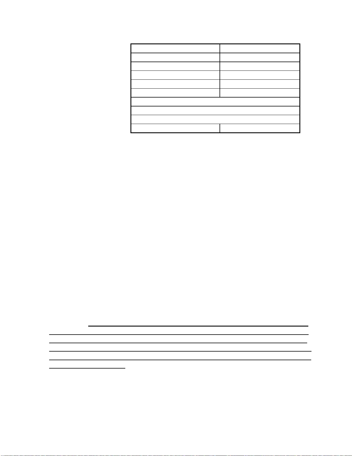
3.0GENERALSPECIFICATION........................................................................................6
4.0TOOLSREQUIREDFORINSTALLATION....................................................................6
5.0CONTENTS...............................................................................................................7
6.0GENERALLIFTSPECIFICATIONS...............................................................................8
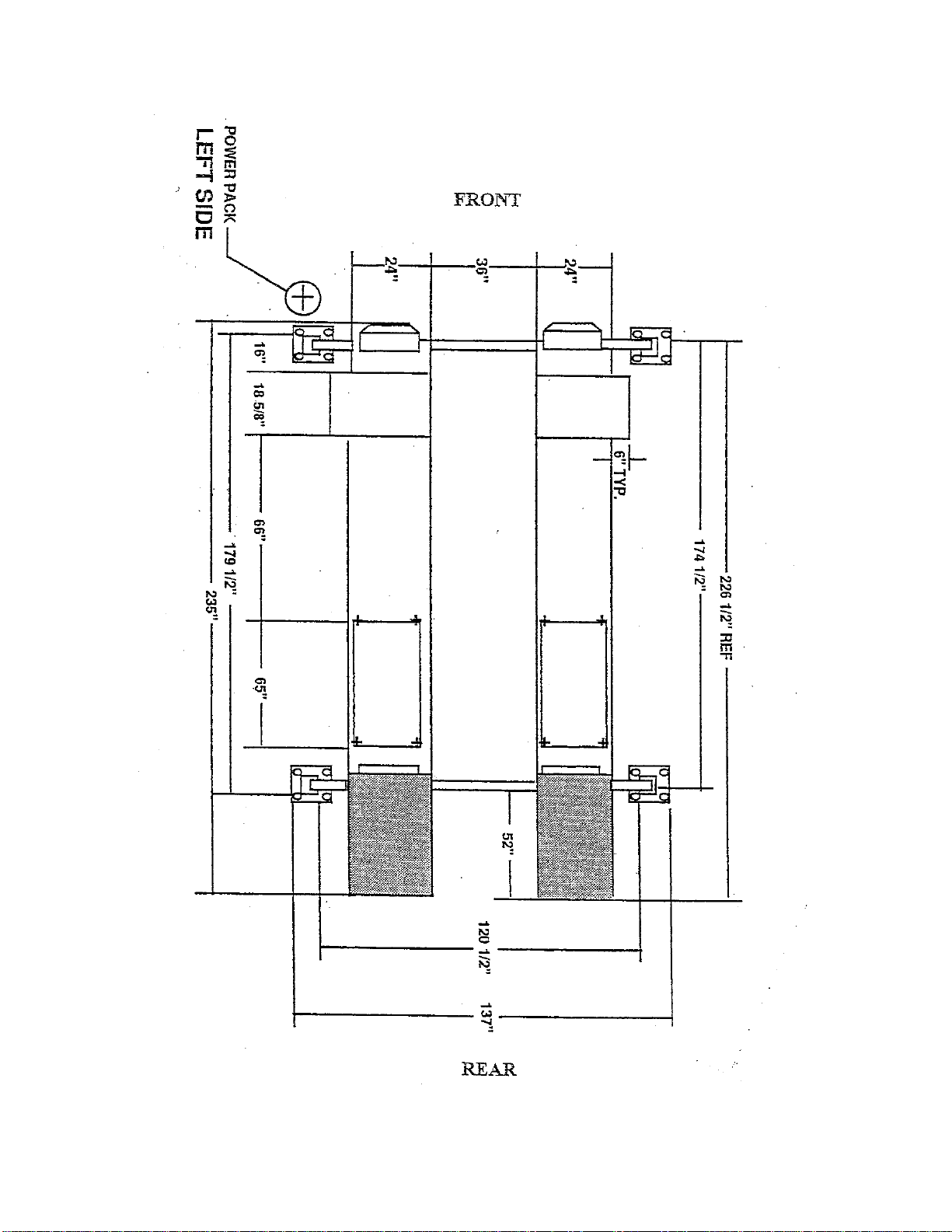
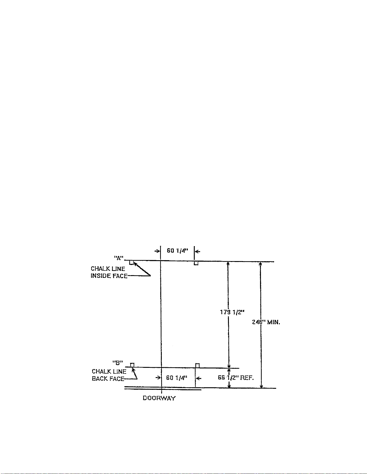
7.0INSTALLATIONINSTRUCTIONS................................................................................9
7.1CHALKLINELAYOUT.........................................................................................9
7.2FRONTANDREARCROSSMEMBERASSEMBLY..............................................11
7.3SHEAVEINSTALLATION...................................................................................12
7.4CABLEINSTALLATION.....................................................................................13
7.5POWERPACKINSTALLATION..........................................................................15
7.6ELECTRICALCONNECTIONS............................................................................16
7.7HYDRAULICINSTALLATION.............................................................................16
7.8AIRINSTALLATIONS........................................................................................17
4.9SAFETYRETAININGSYSTEM...........................................................................18
7.9LEVELINGPROCEDURE...................................................................................19
7.9.1LEVELINGLIFTTOFLOOR.............................................................19
7.9.2DECKLEVELINGPROCEDURE.......................................................19
7.9.3LEVELINGPROCEDURE‐SAFETYLADDERS..................................20
7.10APPROACHRAMPS,WHEELSTOPS,PULLEYCOVERS......................................21
7.11ANCHORINSTALLATION.................................................................................21
7.12SAFETYANDOPERATINGINSTRUCTIONS.......................................................23
7.13FINALCHECKOFASSEMBLEDLIFT..................................................................24
7.14OPERATIONTESTWITHVEHICLE....................................................................25
8.0RECOMMENDEDINSPECTIONANDMAINTENANCE.............................................25
8.1LUBRICATIONSPECS.......................................................................................25
8.2WIREROPES....................................................................................................27
8.2.1WIREROPECONDITIONSGUIDE..................................................27
8.2.2WIREROPEREPLACEMENTCRITERIA:.........................................28
8.2.3WIREROPEINSPECTION..............................................................28
8.2.4WIREROPELUBRICATION............................................................28
8.2.5WIREROPEADJUSTMENT............................................................28
8.2.6INSPECTCABLEFLANGE...............................................................29
8.3FASTENERS......................................................................................................29
8.4SHEAVESANDPINS.........................................................................................29
8.4.1VISUALINSPECTIONOFSHEAVES................................................29
8.4.2MEASURESHEAVEWEAR............................................................29
8.4.3SHEAVEPINS................................................................................30
8.5MECHANICALSAFETYLATCHES(DOGS).........................................................30

5 of 44
8.6CABLEBREAKSAFETYMECHANISM...............................................................30
8.7AIRCYLINDERS,AIRLINES,VALVEANDFITTINGS..........................................30
8.8HYDRAULICPOWERPACKANDHOSE............................................................30
8.9HYDRAULICCYLINDER....................................................................................31
8.10RUNWAYS.......................................................................................................31
8.10.1CHECKRUNWAYS......................................................................31
8.10.2INSPECTJACKBEAMTRACKS....................................................31
8.11COLUMNS.......................................................................................................31
8.11.1CHECKCOLUMNS......................................................................31
8.11.2CHECKCOLUMNANCHORS.......................................................31
8.12APPROACHRAMPS,CHOCKS,FRONTWHEELSTOPS.....................................32
8.13FRONTANDREARSTEERPLATES....................................................................32
8.13.1VISUALINSPECTION..................................................................32
8.13.2CLEANREARSLIPPLATESANDFRONTTURNTABLES...............32
8.13.3MAINTENANCEOFREARSTEERPLATES....................................32
8.13.4MAINTENANCEOFREARSTEERPLATES‐IFEQUIPPEDWITH
PLASTICBEARINGCAGE............................................................32
8.13.5ANTI‐SKIDCOATINGONREARSTEERPLATES...........................32
8.14ROLLINGAIRJACKS.........................................................................................33
8.15ENTIRELIFT.....................................................................................................33
9.0LIFTASSEMBLY......................................................................................................34
10.0HYDRAULICANDAIRKITSASSEMBLY....................................................................37
11.0CABLEROUTINGDIAGRAM...................................................................................39
12.0SAFETYRETAINERBRACKET..................................................................................41
13.0POWERPACK:#6‐1936(AB‐1400)208‐230V/1PH/60HZ......................................42

6 of 44
3.0 GENERALSPECIFICATION
MaximumCapacity:12000lbs.5443kg
OverallLength:235”5969mm
OverallWidth:137”3480mm
DownPositionHeight:9.5”241mm
MaximumLiftingHeight: 71”1803mm
MaximumWheelBase:144”3658mm
RiseTime:60Seconds
PowerRating:230VoltsAC,1Ph.,20Amp,60Hz.
AirRequirements:90‐120psiShopAir
ShippingWeight:3450lbs.1565kg
CHECK CONTENTS OF ACCESSORY BOX WITH THE PACKING LIST ENCLOSED
4.0 TOOLSREQUIREDFORINSTALLATION
ROTARYHAMMERDRILL
1/2”CONCRETEDRILLBIT
SOCKETFORTIGHTENINGANCHORS
4’LEVEL
HAMMER(foranchorinstallation)
PRYBAR(forshiminstallation)
CHALKLINE(liftlocation)
FISH(mechanicswiretofeedcablethroughcrossmemberassembly)
TAPEMEASURE
ELECTRICALTAPE
STEPLADDER(adjustingcablesand/orsafetyladderinposts)
SIDECUTTERS(forcuttingshippingstraps)
BAR(4’long)
4WORKSTANDS(setup)
STANDARDSOCKETSANDWRENCHES
IMPORTANT:Itistheuser’sresponsibilitytoprovideasatisfactoryinstallationareaforthe
lift.Liftsshouldonlybeinstalledonlevelconcretefloorswithaminimumthicknessoffive
(5)inchesor130mm.Concretemusthaveaminimumstrengthof4000psior30MPaand
shouldbeagedthirty(30)dayspriortoinstallation.Pleaseconsultthearchitect,contractor
orengineerifdoubtexistsastothestrengthandfeasibilityofthefloortoenableproperlift
installationandoperation.
Itistheuser’sresponsibilitytoprovideallwiringforelectricalhook‐uppriortoinstallation
andtoinsurethattheelectricalinstallationconformstolocalbuildingcodes.Where
required,itistheuser’sresponsibilitytoprovideanelectricalisolationswitchlocatedin
closeproximitytotheliftthatwillenable emergency stop capability and isolate
electrical power from the lift for any servicing requirements.

7 of 44
ATTENTION! This lift is intended for indoor installation only. It is
prohibited to install this product outdoors. Operating environment
temperature range should be 41 – 104 °F (5 – 40 °C). Failure to
adhere will result in decertification, loss of warranty, and possible
damage to the equipment.
5.0 CONTENTS
Theliftispackagedtoprotectfromanydamagethatmayoccurinshipping.Thetwo
deckassembliesandcrossmembersarepackagedtogetherwiththeaccessoryboxes
strappedtothem.
MainStructuralComponents:
1‐LeftSideDeckAssembly(completewithhydrauliccylinder)
1‐RightSideDeckAssembly
1‐FrontCrossmemberAssembly(withaircylinderreleaselocksandsheaves)
1‐RearCrossmemberAssembly(withaircylinderreleaselocksandsheaves)
AccessoryBoxComponents:
Box1:Contents:
1‐PowerPost(withsafetyladder)
3‐Post(withsafetyladder)
Box2:Contents:
1‐PowerPa1ckAssemblycompletewithFlowControl
2‐ApproachRamps
7‐SheaveAssemblies
1‐SetofCables(setcontains4cableswithnutsandspacers)
7‐SheaveSpacers(differentsizes)
2‐FrontWheelStops
2‐RampPins
4‐DeckSheavePins
1‐AirKit(with1/4”and3/8”polytubeandfittings)
1‐HydraulicHose(withfittings)
1‐HoseGuard
4‐SheaveCovers
3‐CableTie(forattachmentofhydraulichosetocylinder)
2‐RecoiledAirHoses12’long
1‐Coupler1/4”NPT
1‐PackageofHardware(withitsownpackaginglist)
1‐Owner’smanual
1‐ALImanual“LiftingItRight”
1‐AutomotiveLiftSafetyTips
1‐AutomotiveLift,Operation,InspectionandMaintenancemanual

8 of 44
6.0 GENERALLIFTSPECIFICATIONS
Figure1

9 of 44
7.0 INSTALLATIONINSTRUCTIONS
PLEASETAKETHETIMETOREADTHESEINSTRUCTIONSCOMPLETELY.AQUICKCHECKOF
THECONTENTSOFTHEACCESSORYBOXWOULDALSODECREASETHEOVERALLTIMEOFTHE
INSTALLATION.
Gatherthetoolsandmaterialsrequiredfortheinstallation.
Selectthelocationbestsuitedforyourlift.
NOTE:Indeterminingliftareacheckforthefollowing:
Easeofdrivingavehicleonandoffthelift.
Overheadobstructions,lowceilingheight,overheaddoors,overheadheaters,etc.
Floorobstructions,unevenfloorinliftarea,floordrains,workbenches,electrical
infloor,etc.
Anoutlinematchingthedimensionslistedbelowwillneedtobemarkedonthefloor.
RefertoFigure2foroutlinedimensions.RefertoGeneralLiftSpecificationsforoveralllift
dimensions.Figure1.
7.1 CHALKLINELAYOUT
Figure2

10 of 44
RefertoFigure2.Makeachalklineparalleltothedoorwayatleast246inchesinfromthedoorway.
Thiswillbethefurthestfrontfaceofthefrontpostlocation.Callthisline“A”.Determinethecenterof
thedoorwayandbay.Makeacenterlinetointersectwithline“A”.Measurefromthecenterlinealong
line“A”601/4inchesinbothdirections.Thiswillbethelocationoftheinsidefaceandfrontfaceofthe
frontposts.Measurebackfromthisline“A”1791/2inches.Makeachalklineparalleltoline“A”.
Callthisline“B”.Thiswillbethelocationforthebackfaceoftherearposts.Measurefromthe
centerlinealongline“B”601/4inchesinbothdirections.Thiswillbethelocationoftheinsidefaceand
backfaceoftherearposts.Positionworkstandsinsideofline“A”and“B”ofoutline,tosupportthe
frontandrearofeachdeckassembly.
IMPORTANT
NOTE:Todeterminethefront,rear,leftsideandrightsideofthedeckscheck
thefollowing:
Theleftdeckhasthehydrauliccylindermountedtoitsunderside.Therearofthedecks
haveapproachrampbracketstoinstallthedriveonapproachramps.Theworksteps,
attachedtotheturnplatepocketcutoutswillfacetowardsthefrontoutsideofthelift.
Positiondecksonworkstands.
NOTE:TodeterminethefrontandrearcrossmemberassemblyseeFigure3,andcheck
thefollowing:
Thefrontcrossmemberassemblywillhavetwo(2)smallopeningsforthecablerouting.
Theopeningswillfacetherearofthelift.
Therearcrossmemberassemblywillhaveone(1)smallopeningandone(1)largeropening
forcablerouting.Theseopeningswillfacethefrontofthelift.
ThecrossmemberassembliesarefullyassembledandthePULLEYSDONOTNEEDTOBE
REMOVEDFORCABLEINSTALLATION.ALIGNCROSS‐MEMBERASSEMBLIESSOTHATTHE
DIAGONALSMEASUREWITHINHALFANINCHSQUARE.
Installthecrossmemberassembliesunderthefrontandrearofeachdeckassembly.The
deckswillfitinsidethelocatingtabsofthecrossmemberassemblies.Installeight(8)1/2‐
13UNC1”lg.setscrewstoholdthedeckstothecrossmemberassemblies.Oneset
screwtothefrontandrearofeachdeckandonesetscrewintothefourouterlocatingtabs
onthefrontandrearcrossmemberassemblies.
Repositionworkstandsunderfrontandrearcrossmemberassemblies.

11 of 44
7.2 FRONTANDREARCROSSMEMBERASSEMBLY
Figure3
CABLEANDROUTINGINCROSSMEMBERASSEMBLYTYPICAL
Figure4

12 of 44
7.3 SHEAVEINSTALLATION
Figure5

13 of 44
7.4 CABLEINSTALLATION
Locatecablesandsetoutonthefloor.Checkthepartnumberslocatedoneachstudof
eachcable.
CABLE#1...........PART#2‐0643(318”LG.‐L.F.)
CABLE#2...........PART#2‐0644(151”LG.‐L.R.)
CABLE#3...........PART#2‐0645(203”LG.‐R.R.)
CABLE#4...........PART#2‐0646(367”LG.‐R.F.)
NOTE:THEPULLEYS(SHEAVES)ONTHECROSSMEMBERSDONOTHAVETOBEREMOVEDFORCABLE
INSTALLATION.A3/8”‐16UNC23/4”LG.HEXHEADBOLTMUSTBEREMOVEDFROMTHE
CROSSMEMBERSTOALLOWCABLEINSTALLATIONAROUNDTHEPULLEYS.THIS3/8”‐16
UNC23/4”LG.HEXHEADBOLTMUSTBEREINSTALLEDAFTERTHECABLESAREROUTED
THROUGHTHECROSSMEMBERASSEMBLIES.
WARNING!!!
DONOTAPPLYLUBRICANTTOSHEAVEASSEMBLY.FIBREBUSHINGISPTFESELF‐
LUBRICATING.THEADDITIONOFLUBRICANTWILLSHORTENTHELIFEOFTHEFIBRE
BUSHING.
Beforebeginningcablerouting,refertoFigure4CableandRoutingDiagram.
Beginroutingcable#4(part#2‐0646)fromtherightsideofthefrontcrossmember
assemblyusingthenonthreadedendofthecableasdescribedinFigure4,andout
throughtheopeningunderthefrontoftherightdeck.
CHECKFORCORRECTARRANGEMENTOFSPACERSONSHEAVESTACKS,FIGURE5.
InstallthesheaveintothefrontoftherightdeckasshowninFigure5.
NOTE:MAKECERTAINTHATTHECABLERUNSBETWEENTHEWELDED GUIDEPINAND
THEGROOVEINTHEPULLEY.
SHEAVESTACK
Figure6
NOTE:Typicaldecksheavearrangement.Leftandrightfrontdeckshown;cablemustrun
betweentheweldedguidepinandthegrooveinthesheave.Leftandrightfront
spacershaveequaltopandbottomsizes.

14 of 44
NOTE:Similararrangementforsheavestack.Rightdeckrearspacersizesarenotequal‐
largergoesontopofstack.
Continuetopullcable#4overthecentersupportoftherightdeck.
Beginroutingcable#3(Part#2‐0645)fromtherightrearcrossmemberassemblyusing
thenonthreadedendofthecableasdescribedinfigure4,andoutthroughthe
crossmemberassemblytotheopeningundertherearoftherightdeck.
TIP:TAPETHETWOCABLESTOGETHER,CABLE#3ONTOPOFCABLE#4.THISWILLKEEPTHETWO
CABLESFROMTWISTINGINTHEREARCROSSMEMBERASSEMBLIES.
Continuetofeedcables#3and#4throughtherearcrossmemberassemblyandoutofthe
openingundertherearoftheleftdeck.
Installthesheaveintotherearoftherightdeckasshowninfigure5.
Routecable#2(Part#2‐0644)fromtheleftsideoftherearcrossmemberassemblyusing
thenonthreadedendofthecableasdescribedinfigure4,andoutthroughthe
crossmemberassemblytotheopeningundertherearoftheleftdeck.
Routecable#1(Part#2‐0643)fromtheleftsideofthefrontcrossmemberassemblyusing
thenonthreadedendofthecableasdescribedinfigure4,andoutthroughthe
crossmemberassemblytotheopeningunderthefrontoftheleftdeck.
Installthesheaveintothefrontoftheleftdeckasshowninfigure5.
NOTE:MAKECERTAINTHATALLCABLESAREINTHERIGHTPOSITIONSANDARENOTTWISTED.
VERIFYTHATALLFOUR(4)OFTHE3/8”‐16UNC23/4”LG.HEXHEADBOLTSARE
REINSTALLEDONTHECROSSMEMBERASSEMBLIES.
Installthesheavestackassemblyattherearoftheleftdeckasshowninfigure5,Sheave
Installation.
NOTE:ALLPOSTSHAVETHESAFETYRACKSALREADYINSTALLED.THELEFTFRONTPOSTWILLHAVE
AMOUNTINGBRACKETFORTHEPOWERPACKINSTALLATION.
StandpostsintopositionaccordingtoFigure1and2.
Installthethreadedstudendofthecablesthroughthetopofthepost.Usea7/8”flat
washer,andtwo(2)7/8”‐14UNFhexnutswithcablespacersasrequired,tocompensate
forunevenfloors.

15 of 44
7.5 POWERPACKINSTALLATION
Boltthepowerpacktothemountingbracketonthefrontfaceoftheleftfrontpostusing
four(4)5/16”‐18UNC1”LG.hexheadboltsandfour5/16”lockwashers.RefertoFigure
7.
NOTE:WHENWORKINGWITHHYDRAULICLINESANDVALVES,ITISIMPORTANTTOKEEP
ALLCOMPONENTSCLEANANDFREEOFDIRT.
POWERPACKDETAILS
Figure7

16 of 44
7.6 ELECTRICALCONNECTIONS
CAUTION:ALLELECTRICALCONNECTIONSSHOULDBEMADEBYAQUALIFIED
ELECTRICIAN.
PleaserefertoFigure8,ElectricalDiagramfor230volts/1phaseelectricalconnections.
ElectricalBreakerSizeRecommendation:20Amps
ElectricalDiagramfor208‐230V/1Ph/60Hz
Figure8
7.7 HYDRAULICINSTALLATION
RefertoPartsManual,HydraulicandAirKitDiagram
TIP:TAPEONEENDOFTHEHYDRAULICHOSETOTHETWOPOLYTUBESANDFEEDTHEM
THROUGHTHEBLACKPLASTICPIPING.THENREMOVETHETAPE.
Connect3/8”JIC,Mendoftheflexiblehydraulichosetothefittingatthecylinder.
DONOTOVERTIGHTEN.
Installflowcontrolassembly.
Attachtheotherend3/8”JIC,Foftheflexiblehydraulichosetotheadapterfittingonthe
powerpack(3/8”JIC,M).
NOTE:THEHYDRAULICCYLINDERISNOTEMPTY
NOTE:THEPLASTICPLUGONTHEPOWERPACKISNOTUSED.THEREISNOHYDRAULIC
PRESSURE.
NOTE:THECYLINDERRODMUSTBEEXTENDEDINORDERTOINSTALLTHENON‐THREADED
ENDOFTHECABLESTOTHECABLEFLANGEONTHEROD.
Removethehydrauliccapfromthefittingatthebaseofthehydrauliccylinder.
Useanairchuckandblowairintothefittinginthebreatherholeinthebaseofthe
cylindertoextendtherod.

17 of 44
NOTE:ASRODEXTENDS,OILFROMCYLINDERRETURNSTOPOWERPACK.RELEASE
HANDLEONPOWERPACKNEEDSTOBEHELDDOWN(OPEN)TOALLOWOILTO
RETURNTOPOWERPACK.
Continuetoextendtheroduntilthenon‐threadedendofthecablesarereached.
Removetheclampfromthecableflange.
InstallthecablesasshowninFigure4,CableandRoutingDiagram.
Reinstalltheclamptothecableflange.
HYDRAULICANDAIRKITSINSTALLATIONS
Locatethesupplylines:1/4”and3/8”polytube,3/8”flexiblehydraulicline,andtheblack
plasticpiping.
Installtheblackplasticpipingtothesteelpipeweldedtotheundersideofthefrontleft
sidecrossmemberassembly.
7.8 AIRINSTALLATIONS
Attachtheairvalveassemblyusingtwo(2)#8‐32UNC1”lg.Phil.HD.screwstothetwo
(2)#8‐32UNChexnutsontheoutsidefaceoftheleftfrontpost.
NOTE:MOSTOFTHE1/4”AND3/8”POLYTUBECONNECTIONSHAVEBEENMADEINTHE
CROSSMEMBERSASSEMBLIESANDLEFTDECK.ONLYFINALCONNECTIONSAREREQUIREDTO
BEMADE.THE1/4”POLYTUBEWILLBEUSEDFORTHEAIRCYLINDERLOCKSANDTHE3/8”
POLYTUBEWILLBEUSEDFORTHEAIROUTLETSTOTHEJACKINGBEAMS.
CAUTION:DONOTOVERTIGHTENCONNECTORS.
Connectallofthe1/4”polytubes,whichhavebeenpreviouslyinstalled,comingoutofthe
blackplasticpipingattheleftfrontcrossmemberassembly,tothecrossandteepushlock
fittingsatthefrontandrearoftheleftdeck.SeeHydraulic&Airdiagram(Page27).
Connecttheoppositeendofthe1/4”polytube,comingoutoftheblackplasticpiping,to
theairvalveontheoutsidefaceoftheleftfrontpost.
Connectthe3/8”polytube,comingoutoftheblackplasticpipingattheleftfrontcross‐
memberassembly,tothe3/8”polytubefittingatthefrontinsideundertheleftdeck.
Connecttheoppositeendofthe3/8”polytube,comingoutoftheblackplasticpiping,to
theairvalveoutletontheoutsidefaceoftheleftpost.
NOTE:FORTHOSEUNITSEQUIPPEDWITHJACKINGBEAMS,THISWOULDBETHETIMETOINSTALL
THEM.CONSULTTHEJACKINGBEAMINSTRUCTIONSMANUALFOUNDINEACHJACKBEAM
BOX.
‐ IFJACKBEAMSAREINSTALLED,PLUGTHEONEREMAININGOUTLETATTHEFRONTAND
REAROFTHELIFT.
‐ IFJACKBEAMSARENOTINSTALLED,USEPLUGSAND/ORCOUPLERSTOPLUGAIR
OUTLETS.

18 of 44
Hookupanairsupplytotheinletofthewatertrapontheairvalveassemblylocatedon
theoutsideoftheleftpost.
Checkforairleaks.
Checktheoperationoftheaircylinderlocksbydepressingtheairvalveontheoutsideof
theleftfrontpost.
Pressthe“UP”buttononthehydraulicALLpowerpack.Continueraisinguntiltheliftis
supportedbythecables.
NOTE:MAKECERTAINTHATTHEMECHANICALSAFETYLOCKSANDCABLEROLLERSAREWORKING
PROPERLY.
4.9SAFETYRETAININGSYSTEM
Assemblethesafetyretainerbracketassembliesusingthesuppliedhardwareasshownin
Section10.
Installone5/16”x¾”longhexheadboltwithone5/16”lockwasherandone5/16”flat
washerintothetopmountingholelocationonthecrossmemberbutdonottighten.
Leaveatleast3/16”spacebetweenthelockwasherandthecrossmember.
Insertthebracketassemblyinsidethepostandslideupintoplacebetweenthepostand
thecrossmembersothattheboltandwashersslideintotheupperslot.
Installthesecond5/16”x¾”longhexheadboltand5/16”lockwasherandflatwasher
throughthelowerslotandintothebottommountingholeinthecrossmember.Tighten
bothofthebolts.SeeFigure9.
Repeatforallsidesofcrossmembers.
Figure9.Retainerbracketinstallation
Retainer Bracket
Assembly (2-2593)
Hex HD Bolts
5/16” x ¾” LG
(6-0423)
5/16” Lock Washers
(6-0674)
5/16” Flat Washers
(6-0295)

19 of 44
7.9 LEVELINGPROCEDURE
7.9.1 LEVELINGLIFTTOFLOOR
Lowertheliftcompletelytothefloor.
Determinethehighestcorneroftheliftandadjustremainingtowerstolevelthelift,front‐
to‐backandside‐to‐side(Seepositions1,2,3and4inFig.11).Useshimsundertower
baseplate,asneeded.
7.9.2 DECKLEVELINGPROCEDURE
NOTE:Useafour(4)footleveltoadjustthecablestolevelthedecksside‐to‐sideandfront‐
to‐rear.Allcableadjustmentscanbemadeatthethreadedendofthecableatthe
topofeachofthefour(4)posts.
Tightenthetwo(2)7/8”‐14UNFhexnutsoneachcableatthetopofeachpost.
Raisethelifttocheckoperation.
Lowerliftbydepressingtheairvalvewhilepullingdownonthereleaseleverofthepower
pack.
Removehandfromairvalveandallowthelifttohangonthecables.
Useafour(4)footlevel.Levelandsquareallfourposts.
Beginlevelingthehighestpost.
POSTLEVELING
Figure10
NOTE:MAKECERTAINTHATTHESAFETYRACKINEACHOFTHEPOSTSISSQUARETOTHE
CROSSMEMBERASSEMBLYANDTHATAMINIMUMCLEARANCEOF1/8”ISMAINTAINED
BETWEENTHEINSIDEFACEOFTHEPOSTSANDTHEPLASTICGUIDESONTHECROSSMEMBER
ASSEMBLY.
CAUTION:USETHECORRECTWEDGEANCHORBOLTS.(SUPPLIED)

20 of 44
DECKLEVELING
Figure11
(Liftmaynotbeasshown)
NOTE:Checkandadjustthedecksforlevelusingthe4’level.Boththefrontplatecut‐outs
andrearsteerplatesshouldbechecked.
7.9.3 LEVELINGPROCEDURE‐SAFETYLADDERS
1.Afterthelifthasbeenleveledonthecables,adjustthesafetyracks.
2.Tocheckthemechanicalsafetylocks,raisetheliftup;makesurealllocksengageatthe
sametimemakingonenoise.Ifthesafetiesareoffslightly,gentlybumptheupbutton
untilyouhearthefirstsafetylockengage.Determineatwhichpostthesafetyengaged;
adjusteachoftheothersafetyracksuntilyouhearthesafetyengage.Rechecktomake
certainthatthesafetiesareengagingtogether.
3.Todothisloosenthe3/8”‐16UNC1”lg.hexboltatthebottombackofeachpostand
pullsafetyracksupuntiltheycomeintofullcontactwitheachofthe safetyshoesonthe
crossmemberassembly.
This manual suits for next models
1
Table of contents
Other Hofmann Lifting System manuals