HOGG & DAVIS ODP 100PPS TM User manual

ODP 100PPS TM
The information, specifications, and illustrations in this manual are on
the basis of information available at the time it was written. The
specifications, torque values, pressures of operation, measurements,
adjustments, illustrations, and other items can change at any time.
These changes can affect the service of the given product.
For the complete and most current information, contact:
Hogg & Davis, Inc
P.O. Box 405 / 3800 Eagle Loop
Odell, OR 97044-0405
541-354-1001
541-354-1080 Fax
For most recent manual
version please visit:
www.hoggdavis.com
ver. 1.0

ODP 100PPS TM
10,000 Lb Drum Puller
Table of Contents
Table of Contents......................................................................................- 2 -
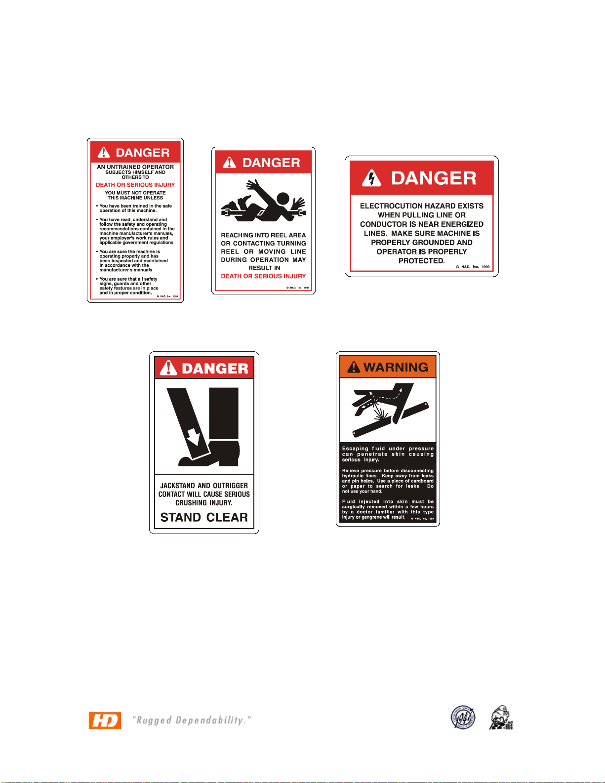
Product Warnings......................................................................................- 3 -
General Specifications.............................................................................- 4 -
Puller – Main Unit Curb Side...............................................................- 5 -
Puller – Main Unit – Street Side..........................................................- 7 -
Control Panel.......................................................................................- 8 -
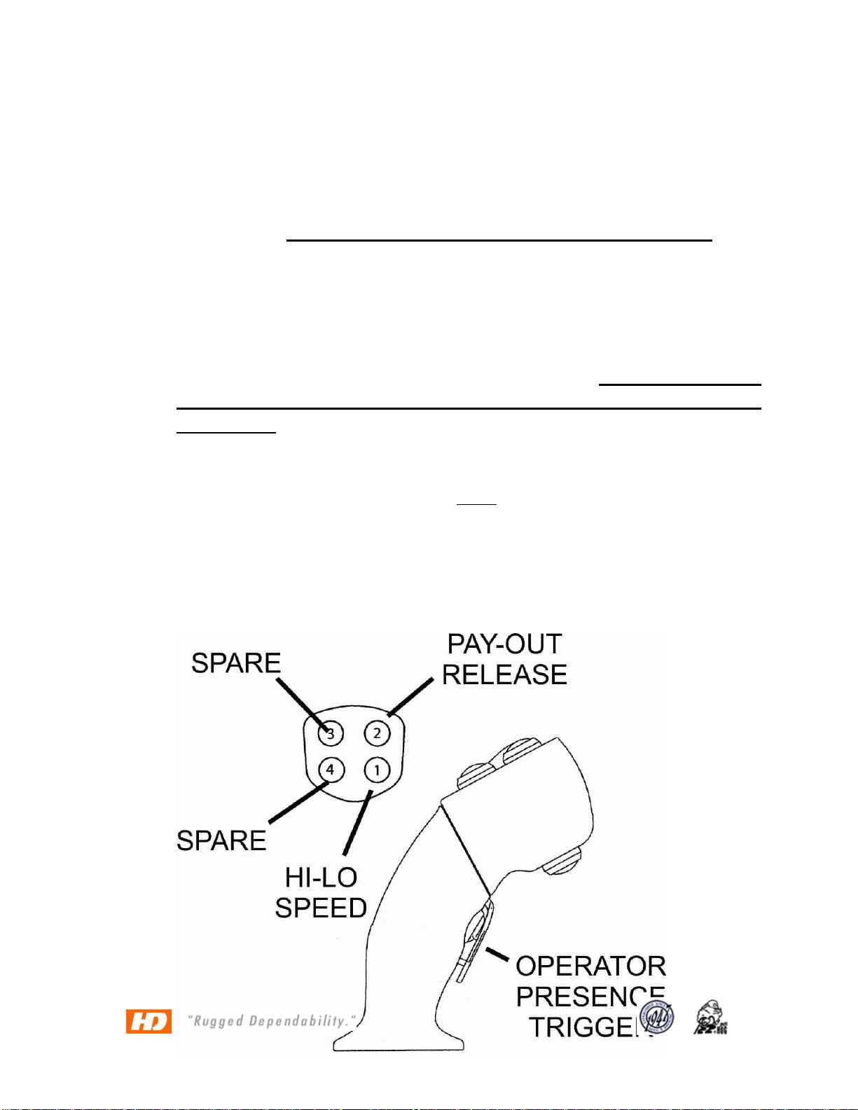
Joystick Functions......................................................................................- 9 -
Drive Engagement..................................................................................- 11 -
Setup on the Job.....................................................................................- 12 -
Setup of the unit...................................................................................- 12 -
Position of unit....................................................................................- 12 -
Tie Down/ Brake/ Chock..................................................................- 12 -
Rope Payout Procedure (Free Wheel)................................................- 13 -
Pulling Computer.....................................................................................- 13 -
Operation..............................................................................................- 14 -
Setup Screen......................................................................................- 14 -
Set Pull.................................................................................................- 15 -
Pull Screen - MAIN.............................................................................- 15 -
Hours Screen......................................................................................- 17 -
System Screen....................................................................................- 18 -
Joystick................................................................................................- 19 -
Engine..................................................................................................- 20 -
Pulling Control..........................................................................................- 21 -
System Brakes.....................................................................................- 21 -
Level wind..............................................................................................- 21 -
LUBRICATION AND MAINTENANCE.......................................................- 21 -
Set Screws...........................................................................................- 22 -
15-15 Warranty......................................................................................- 23 -
Parts and other manufacturer manuals..............................................- 24 -
- - 2 - -
© COPYRIGHT 2013 HOGG & DAVIS, INC

ODP 100PPS TM
10,000 Lb Drum Puller
Product Warnings
These warning labels and others like
it are placed in critical areas of the
machine. The warnings are to be
read and fully understood prior to
operation of the unit.
- - 3 - -
© COPYRIGHT 2013 HOGG & DAVIS, INC

ODP 100PPS TM
10,000 Lb Drum Puller
General Specifications
This unit is designed to install / tension overhead cable/conductor.
•Single Reel Puller
•Pulling Computer
•Constant Line Pull System
•10,000 lbs Maximum Line Pull
•185 hp John Deere Tier III Diesel
•20,000’ of 1” synthetic rope capacity
•Post Style Level wind
•Dual Drive System
•Fuel Capacity – 60 Gallons
•Hydraulic Oil Capacity – 59 Gallons
- - 4 - -
© COPYRIGHT 2013 HOGG & DAVIS, INC

ODP 100PPS TM
10,000 Lb Drum Puller
Operating Instructions
All persons operating this machine must read and understand this
manual as well as the operating, danger, and warning decals
placed on the machine. Failure to read and understand these items
subjects the operator and others to DEATH or SERIOUS INJURY.
Operators shall make themselves familiar with the placement of the
following operating and safety features of the machine.
Puller – Main Unit Curb Side
1. Grounding Lugs. There are two lugs welded to rear of the
truck chassis. They are to be used for grounding only.
2
3
4
6
5
7
1
- - 5 - -
© COPYRIGHT 2013 HOGG & DAVIS, INC

ODP 100PPS TM
10,000 Lb Drum Puller
2. Operators Station
3. Hydraulic Oil Cooler. This unit transfers the heat from the
hydraulic oil during use. It is to be kept clean and clear of
dust and debris. Failure to do so may increase hydraulic
system operating temperature and may also damage the
components in the system.
4. Drive Dog Clutches. There is a unit located on both sides.
These are the primary drives for the pulling operation. DO
NOT OPERATE THE UNIT WITHOUT BOTH DRIVES ENGAGED.
It may be necessary for the operator to rotate the reel to
allow for the drive dogs to be engaged
5. Brake Rotor and Caliper. This brake system is for use during
the free wheel payout of the installation rope. During the free
wheel operation of the unit, this rotor will become extremely
hot. DO NOT OPERATE THE PULLING FUNCTION OF THIS UNIT
WHILE THE BRAKE SYSTEM IS APPLIED.
6. Level wind. This unit is controlled by a momentary switch on
the operator’s console. It is independently operated.
7. Hydraulic Tank. ISO 46 or equivalent. 62 gallons
- - 6 - -
© COPYRIGHT 2013 HOGG & DAVIS, INC

ODP 100PPS TM
10,000 Lb Drum Puller
Puller – Main Unit – Street Side
1. Grounding Lug
2. Engine Access
3. Oil cooler and radiator
4. Chain Guards. Located on both sides of large secondary
sprocket. DO NOT OPERATE PULLER WHILE THESE ARE NOT ON
THE UNIT.
5. Drive Dog Clutches. There is a unit located on both sides.
These are the primary drives for the pulling operation. DO NOT
OPERATE THE UNIT WITHOUT BOTH DRIVES ENGAGED.
6. Fuel Tank
7. Level Wind
1
2
3
4
5
6
7
- - 7 - -
© COPYRIGHT 2013 HOGG & DAVIS, INC

ODP 100PPS TM
10,000 Lb Drum Puller
Control Panel
1. Over spin Brake Pressure. This gauge displays the pressure at
which the Over spin Brake is operating. DO NOT EXCEED 600
PSI.
2. Sensor Heat. In cold conditions, it may be necessary to heat
the pulling sensor for a few minutes prior to operation
1
2
3
4
5
6
- - 8 - -
© COPYRIGHT 2013 HOGG & DAVIS, INC

ODP 100PPS TM
10,000 Lb Drum Puller
3. Over spin Brake. This controls the over spin brake and at what
pressure you apply. Clockwise to apply and counter clockwise
to release. DO NOT OPERATE PULLER WITH BRAKE APPLIED.
Damage to the brake caliper and rotor may occur as well as
providing false pressure readings.
4. Level wind control.
5. Drive dog ENGAGE / DISENGAGE SWITCHES DO NOT OPERATE
UNIT WITHOUT BOTH DRIVES ENGAGED OR DISENGAGED AT THE
SAME TIME
6. Joystick. This joystick is a friction style control. It has a positive
stop but releasing control will NOT return control to neutral. In
order to stop pull, operator must return joystick to neutral.
Joystick Functions
- - 9 - -
© COPYRIGHT 2013 HOGG & DAVIS, INC

ODP 100PPS TM
10,000 Lb Drum Puller
•Pay Out Release. This button must be pressed while
attempting to pay out under power. By pressing the
Operator Presence Trigger while pressing the Pay Out
Release, moving the Joystick towards the Pay Out position
will allow the reel to pay out under power. Once the reel
begins to pay out, these buttons may be released. The
Pay Out Lockout will automatically reset when the Joystick
is returned to neutral.
•Hi-Lo Speed. Pressing this button during take up or payout
will manually shift the pull speed. Although the computer
is still in control of the maximum line speed and line pull
and it will not be exceeded.
•Operator Presence Trigger. This but be pressed during the
beginning of all Joystick functions. Once the unit is
working, it may be released. The trigger will reset when
the Joystick is returned to neutral.
Warning: These functions are present to protect the operator and the
crews on the ground. If any of these are not functioning properly,
contact vendor immediately. These are not to be circumvented in
any way. Creating shortcuts to control machines of this nature can
cause SERIOUS INJURY or DEATH to those operating this machine and
those that are working with it.
Engaged
- - 10 - -
© COPYRIGHT 2013 HOGG & DAVIS, INC

ODP 100PPS TM
10,000 Lb Drum Puller
Drive Engagement
Above is a top view of the drive dog couplers in their engaged and
disengaged state. Please be sure all clutch pins are installed when
engaged and disengaged, or damage may occur.
Disengaged
- - 11 - -
© COPYRIGHT 2013 HOGG & DAVIS, INC

ODP 100PPS TM
10,000 Lb Drum Puller
Setup on the Job
Setup of the unit
Hogg & Davis, Inc. recommends following the methods described in
the following publications:
IEEE Std 524-1992
IEEE Guide to the Installation of Overhead Transmission Line
Conductors
IEEE Std 542a-1993
IEEE Guide to Grounding During the Installation of Overhead
Transmission Line Conductors
Position of unit
Position the unit with the centerline of the trailer in line with the pull.
Place the unit at a minimum of two times the height of the first block.
Positioning the unit this way decreases the stress on the level wind
system.
Tie Down/ Brake/ Chock
Chock all wheels and set brakes (if applicable). It should be noted
that the fully loaded puller weight may exceed the tension desired
during the pull. As the pull progresses, the weight of the puller may
increase or decrease, therefore proper securing procedures should
be followed during operation.
- - 12 - -
© COPYRIGHT 2013 HOGG & DAVIS, INC

ODP 100PPS TM
10,000 Lb Drum Puller
Rope Payout Procedure (Free Wheel)
When beginning the rope payout feature, be sure that the engine is
turned off. Ensure that all tension is removed from the pulling rope
before attempting to release drive dogs.
Adjust reel brake to provide tension to the reel of rope. Disengage
the drive dog(s) from the sprocket drive(s). Begin to pull rope
through the blocks while continuing to adjust the over spin brake.
When the rope install is completed, engage the sprocket drive(s).
***These instructions assume that the operator has set the proper
drive dog(s) for the reel to be pulled in.
Pulling Computer
This unit is equipped with a computer control that allows the
operator to preset the Maximum Line Pull as well as the Maximum
Line Speed. During the pull, no matter the length of cable in the air,
the computer calculates the drum diameter and adjusts the
hydraulic system to provide a constant pulling control. Throughout
the pull, the Line Pull and the Line Speed will be maintained at a
constant set by the operator. This type of system allows for greater
control of the overall pull, as well as eliminating the “estimation
process” and constant adjustment of hydraulic system to maintain
the maximum preset.
- - 13 - -
© COPYRIGHT 2013 HOGG & DAVIS, INC

ODP 100PPS TM
10,000 Lb Drum Puller
Operation
Setup Screen.
Select the page using the “up-down” buttons and then press enter.
- - 14 - -
© COPYRIGHT 2013 HOGG & DAVIS, INC

ODP 100PPS TM
10,000 Lb Drum Puller
Set Pull
There can be up to four preset “Pulls” in the computer at one time.
They are labeled, Pull 1-4 and utilize the corresponding buttons on
the left hand side of the pulling computer control.
Select the pull you wish to modify and increase the Maximum Pull by
using the “up-down” buttons. When the desired Line Pull Max is set,
press enter.
The computer can also control the line speed for that set pull. The
buttons on the right side of the pulling computer 5-8 correspond with
the pulls set 1-4. Pressing the 5-8 buttons will allow the operator to set
the maximum Line Speed for the pull. FPM and MPH are both
displayed. They are set relevant to the other. Example 352 FPM = 4.0
MPH.
When the Maximum Line Pull and Line Speed are set, press the ESC
key and return to Pull Screen.
Pull Screen - MAIN
The pull screen displays the most needed displays for the pull.
•Pull – This displays the Current Line Pull in lbs. NOT THE MAXIMUM
•Fuel – Fuel Level in the Puller tank.
•Drum Diameter – Current diameter of the drum.
•FPM – Current FPM
•MPH – Current MPH
•Engine Gauges – This display’s the engine temp, oil pressure,
RPM PCT of Load and battery voltage.
•Throttle – The engine throttle is increased or decreased by using
the Left-Right buttons on each side of the OK button.
- - 15 - -
© COPYRIGHT 2013 HOGG & DAVIS, INC

ODP 100PPS TM
10,000 Lb Drum Puller
•Menu – Returns to the Main Menu Screen.
•Pull and Speed – Below the Menu label on the screen, the
PRESET Maximum Line Pull and Speed are displayed.
•Select Pull – This button brings up the Select Pull Screen.
•Camera – If the unit is equipped, this will allow for remote
viewing.
- - 16 - -
© COPYRIGHT 2013 HOGG & DAVIS, INC

ODP 100PPS TM
10,000 Lb Drum Puller
Hours Screen
This screen displays the current hours on the engine oil filters,
hydraulic oil filters, the time the winch has been activated (pay in
and pay out time) and engine hours.
- - 17 - -
© COPYRIGHT 2013 HOGG & DAVIS, INC

ODP 100PPS TM
10,000 Lb Drum Puller
System Screen
This screen displays the current System Pressure, Charge Pressure,
Motor RPM, and the Drum Diameter. This screen is primarily used for
troubleshooting.
- - 18 - -
© COPYRIGHT 2013 HOGG & DAVIS, INC

ODP 100PPS TM
10,000 Lb Drum Puller
Joystick
This screen gives a graphic display of the Joystick and its functions.
- - 19 - -
© COPYRIGHT 2013 HOGG & DAVIS, INC

ODP 100PPS TM
10,000 Lb Drum Puller
Engine
This screen displays all current information regarding the engine on
the puller.
***These instructions assume that the operator has set the proper
drive dog(s) for the reel to be pulled in.
- - 20 - -
© COPYRIGHT 2013 HOGG & DAVIS, INC
Table of contents
Other HOGG & DAVIS Construction Equipment manuals