HOKUBEMA PANHANS 546|100 User manual

TRANSLATION OF THE ORIGINAL VERSION
HOKUBEMA Maschinenbau GmbH
Graf-Stauffenberg-Kaserne, Binger Str. 28 | Halle 120
DE 72488 Sigmaringen | Tel. +49 07571 755-0
E-Mail: info@hokubema-panhans.de | Web: https://hokubema-panhans.de
Operating Manual
Combined Surface Planer & Thicknesser
PANHANS 546|100
Machine Type:
546|100

BA_PH_546-100_EN_06-22.docx
2
Table of Contents
1Introduction.................................................................................................................................................... 7
1.1 Legal Notice ............................................................................................................................................................ 7
1.2 Illustrations ............................................................................................................................................................. 7
2Symbols .......................................................................................................................................................... 7
2.1 General Symbols ..................................................................................................................................................... 7
2.2 Symbols in Safety Instructions ................................................................................................................................ 8
3General........................................................................................................................................................... 9
3.1 Target Group and Previous Experience................................................................................................................... 9
3.2 Requirements for the Operators............................................................................................................................. 9
3.3 Accident Prevention................................................................................................................................................ 9
3.4 General Safety Regulations................................................................................................................................... 10
3.5Structure and Function ......................................................................................................................................... 11
3.6 Advantages & Special Features of the Machine.................................................................................................... 11
3.7 Standard Equipment ............................................................................................................................................. 12
3.8 Available Options.................................................................................................................................................. 12
4Safety............................................................................................................................................................ 13
4.1 Basic Safety Instructions ....................................................................................................................................... 13
4.1.1 Application Area and Intended Use............................................................................................................. 13
4.1.2 Modifications and Conversions to the Machine.......................................................................................... 13
4.1.3 Residual Risks .............................................................................................................................................. 14
4.2 Observe the Environmental Protection Regulations............................................................................................. 15
4.2.1 Organisational Measures............................................................................................................................. 15
4.2.2 Personnel Selection and Qualification - Basic Duties .................................................................................. 15
4.3 Safety Instructions for Specific Phases of Operation ............................................................................................ 16
4.3.1 Normal Operation ....................................................................................................................................... 16
4.3.2 Special work within the Scope of Maintenance Work as well as Troubleshooting in the Workflow .......... 17
4.3.3 Safe Working Practices................................................................................................................................ 17
4.4 Hazardous Areas ................................................................................................................................................... 18
4.4.1 Danger Zones during Surface Planing.......................................................................................................... 18
4.4.2 Working Areas & Protective Measures ....................................................................................................... 18
4.4.3 Danger Zones during Thicknessing.............................................................................................................. 19
4.4.4 Working Areas & Protective Measures ....................................................................................................... 19
5Machine Data ............................................................................................................................................... 20
5.1 Technical Specifications ........................................................................................................................................ 20
5.2 Technical Features ................................................................................................................................................ 20
5.3 Emission Levels ..................................................................................................................................................... 21
5.3.1 Noise Information ....................................................................................................................................... 21
5.3.2 Noise Emission Values................................................................................................................................. 21

BA_PH_546-100_EN_06-22.docx
3
6Dimensions................................................................................................................................................... 22
6.1 Front & Top View .................................................................................................................................................. 22
6.2 Side View............................................................................................................................................................... 23
7Installation and Connection ......................................................................................................................... 24
7.1 Check Delivery Conditions .................................................................................................................................... 24
7.2 Transport .............................................................................................................................................................. 24
7.3 Installing the Machine........................................................................................................................................... 24
7.4 Temporary Storage ............................................................................................................................................... 25
7.5 Lashing on a Transport Vehicle ............................................................................................................................. 25
7.6 Connecting the Extraction Unit............................................................................................................................. 26
7.7 Electrical Connections........................................................................................................................................... 27
7.8 Backup Fuse .......................................................................................................................................................... 27
7.9 Supply Cable.......................................................................................................................................................... 27
7.10 Machine Socket (Option) ...................................................................................................................................... 27
7.11 Attachment of Auxiliary Equipment...................................................................................................................... 27
8Components and Controls............................................................................................................................ 28
8.1 Machine Components........................................................................................................................................... 28
8.2 Control Panel Planer & Jointer (Detail View) ........................................................................................................ 30
8.3 Control Panel Thicknesser (Detail View) ............................................................................................................... 30
9Commissioning ............................................................................................................................................. 31
9.1 Switching the Machine ON and OFF ..................................................................................................................... 31
9.1.1 Surface Planing & Jointing........................................................................................................................... 31
9.1.2 Thicknessing ................................................................................................................................................ 31
9.1.3 Combined Working...................................................................................................................................... 32
9.1.4 Emergency Stop System .............................................................................................................................. 32
10 Operation ..................................................................................................................................................... 33
10.1 Surface Planing & Jointing..................................................................................................................................... 33
10.1.1 Electrical Adjustment of the Infeed Table................................................................................................... 33
10.1.2 Adjusting the Outfeed Table ....................................................................................................................... 33
10.1.3 Adjustable Outfeed Table (Option) ............................................................................................................. 33
10.1.4 Operating the Planing Fence ....................................................................................................................... 34
10.1.5 Auxiliary Fence ............................................................................................................................................ 34
10.1.6 Push Block ................................................................................................................................................... 34
10.1.7 Calibrating the Planing Fence (Position 90°) ............................................................................................... 35
10.1.8 Calibrating the Planing Fence (Position 45°) ............................................................................................... 35
10.2 Planer Guard TXF 1570 ......................................................................................................................................... 36
10.2.1 Flat Planing.................................................................................................................................................. 36
10.2.2 Edge Jointing ............................................................................................................................................... 36
10.3 Optional Planer Guards SUVAMATIC & TX MATIC ................................................................................................ 36
10.4 Thicknessing via Touchscreen Control .................................................................................................................. 37
11 Touchscreen Control Unit ............................................................................................................................ 37

BA_PH_546-100_EN_06-22.docx
4
11.1 Buttons and Symbols ............................................................................................................................................ 37
11.2 Activating the Controller....................................................................................................................................... 38
11.3 Operating States & Language ("Info" Menu) ....................................................................................................... 38
11.4 Positioning Mode (“Machine” Menu)................................................................................................................... 39
11.4.1 Table Height Positioning in Absolute Mode ................................................................................................ 39
11.4.2 Table Height Positioning in Incremental Mode ........................................................................................... 39
11.5 Calibrating the Table Height (“Setup” Menu) ....................................................................................................... 40
11.6 Feed Rate Visualisation (Option)........................................................................................................................... 40
11.7 Warnings and Error Messages .............................................................................................................................. 41
11.7.1 Error Messages............................................................................................................................................ 41
11.7.2 Warnings ..................................................................................................................................................... 42
12 Fine adjustable Table Rollers (Option) ......................................................................................................... 43
12.1 Adjusting the Table Rollers ................................................................................................................................... 43
13 Changing the Planer Knives .......................................................................................................................... 43
13.1 Changing the TERSA Knives on an All-Steel Cutter Block (standard)..................................................................... 43
13.2 Changing the Knives on PANHANS Traditional Cutter Block (Option)................................................................... 44
13.2.1 PANHANS Cutter Block Adjusting Devices................................................................................................... 44
13.2.2 Magnetic Quick Adjusters 1533 (Option) .................................................................................................... 45
13.3 Changing the Knives on PANHANS Spiral Cutter Block (Option) ........................................................................... 46
13.3.1 Procedure for Changing the Knives ............................................................................................................. 46
13.3.2 Advantages of the PANHANS Spiral Cutter Block........................................................................................ 46
14 Troubleshooting ........................................................................................................................................... 47
15 Maintenance and Inspection........................................................................................................................ 48
15.1 Lubrication Instructions ........................................................................................................................................ 48
15.2 Replace / Tighten the V-Belts................................................................................................................................ 49
15.3 Retighten the Feed Chain...................................................................................................................................... 49
15.4 Adjusting the Fingers of the Anti-Kickback Device................................................................................................ 49
15.5 Replace Rubber Rollers ......................................................................................................................................... 50
16 Options and Accessories .............................................................................................................................. 52
16.1 Cutter Blocks and Planing Knives .......................................................................................................................... 52
16.1.1 Accessories for Tersa Cutter Blocks (Standard)........................................................................................... 52
16.1.2 Accessories for Traditional Cutter Blocks (Option)...................................................................................... 52
16.1.3 Accessories for Spiral Cutter Block (Option)................................................................................................ 52
16.2 Optional Table Systems......................................................................................................................................... 53
16.3 Planer Guards........................................................................................................................................................ 53
16.4 Special Accessories ............................................................................................................................................... 53
17 Disassembly and Scrapping .......................................................................................................................... 54
EU - Declaration of Conformity............................................................................................................................. 55

BA_PH_546-100_EN_06-22.docx
5
List of Figures
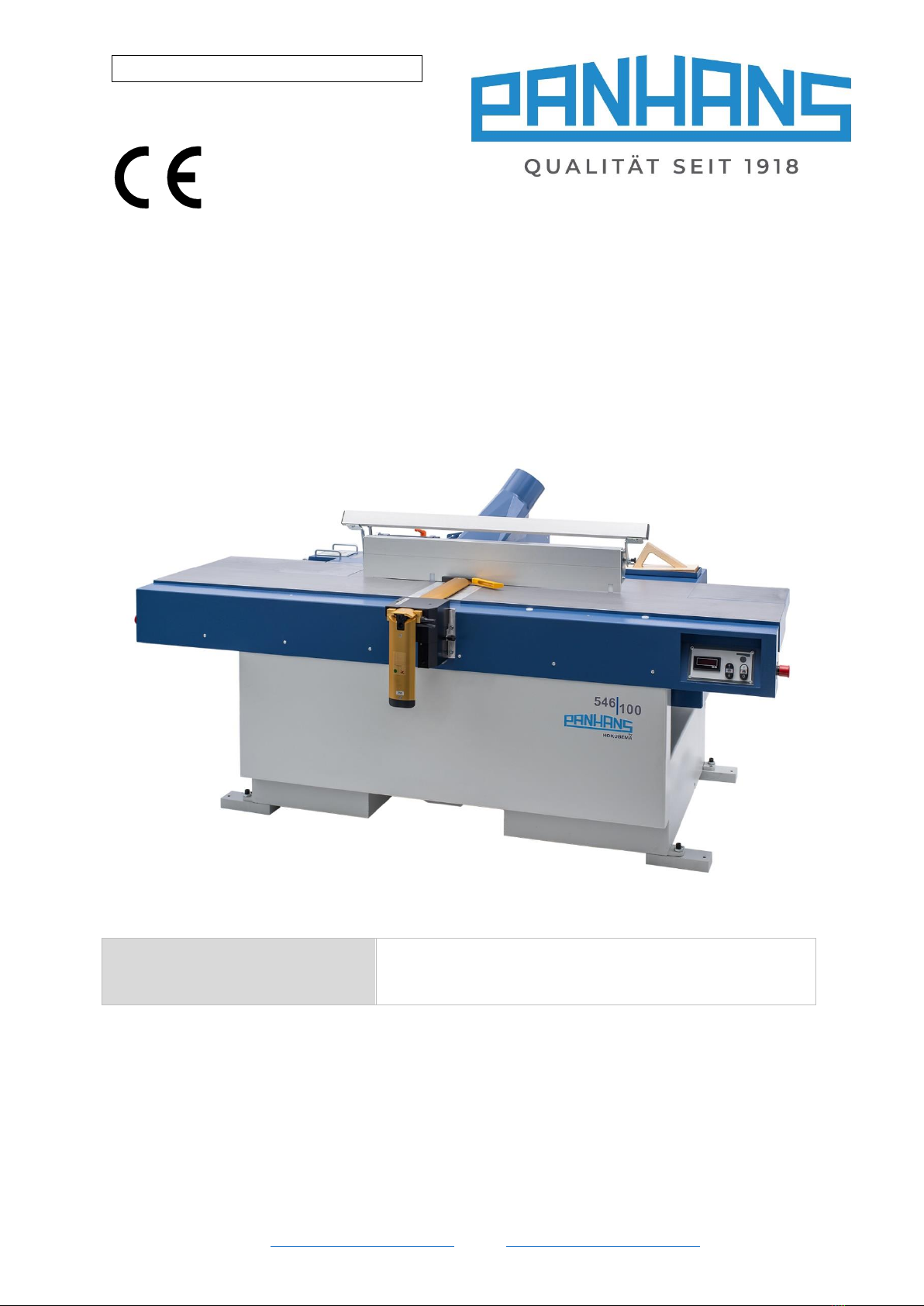
Figure 1: 546|100.................................................................................................................................................... 7
Figure 2: Danger zones during surface planing..................................................................................................... 18
Figure 3: Danger zones during thicknessing.......................................................................................................... 19
Figure 4: Nameplate.............................................................................................................................................. 20
Figure 5: Working areas ........................................................................................................................................ 21
Figure 6: Dimensions top & side view................................................................................................................... 22
Figure 7: Dimensions side view............................................................................................................................. 23
Figure 8: Transportation ....................................................................................................................................... 24
Figure 9: Foot underlay ......................................................................................................................................... 24
Figure 10: Lashing points (4 x)............................................................................................................................... 25
Figure 11: Extraction ports.................................................................................................................................... 26
Figure 12: Main switch housing ............................................................................................................................ 27
Figure 13: Components & controls (front view) ................................................................................................... 28
Figure 14: Components & controls (side & rear view).......................................................................................... 29
Figure 15: Control panel planer & jointer (standard)............................................................................................ 30
Figure 16: Control panel thicknesser (standard)................................................................................................... 30
Figure 17: Control panel thicknesser (optional).................................................................................................... 30
Figure 18: Planing & jointing controls................................................................................................................... 31
Figure 19: Thicknessing controls........................................................................................................................... 32
Figure 20: Emergency stops .................................................................................................................................. 32
Figure 21: Operation “planing & jointing” ............................................................................................................ 33
Figure 22: Outfeed table adjustment.................................................................................................................... 33
Figure 23: Top view of the surface planing fence ................................................................................................. 34
Figure 24: Auxiliary fence...................................................................................................................................... 34
Figure 25: Push block in compartment ................................................................................................................. 34
Figure 26: Check angle 90 degrees........................................................................................................................ 35
Figure 27: Calibrate angle to 90 degrees .............................................................................................................. 35
Figure 28: Calibrate angle to 45 degrees .............................................................................................................. 35
Figure 29: Planer guard TXF 1570 ......................................................................................................................... 36
Figure 30: Guard setting for flat planing............................................................................................................... 36
Figure 31: Guard setting for edge jointing ............................................................................................................ 36
Figure 32: Type SUVAMATIC (example) ................................................................................................................ 36
Figure 33: Touchscreen control unit ..................................................................................................................... 37
Figure 34: Screen at start-up (booting)................................................................................................................. 38
Figure 35: Screen “ready for use” ......................................................................................................................... 38
Figure 36: Info menu with status messages.......................................................................................................... 38
Figure 37: Language menu.................................................................................................................................... 38
Figure 38: Setpoint input in absolute mode.......................................................................................................... 39
Figure 39: Position reached in absolute mode...................................................................................................... 39
Figure 40: Setpoint input in incremental mode .................................................................................................... 39
Figure 41: Setpoint reached.................................................................................................................................. 39
Figure 42: Calibrate table height........................................................................................................................... 40
Figure 43: Input of the reference value ................................................................................................................ 40
Figure 44: Feed rate visualisation ......................................................................................................................... 40
Figure 45: Error message 1 ................................................................................................................................... 41
Figure 46: Error message 2 ................................................................................................................................... 41
Figure 47: Error message 3 ................................................................................................................................... 41
Figure 48: Error message 4 ................................................................................................................................... 41
Figure 49: Error message 5 ................................................................................................................................... 41
Figure 50: Error message 6 ................................................................................................................................... 41
Figure 51: Warning 1............................................................................................................................................. 42

BA_PH_546-100_EN_06-22.docx
6
Figure 52: Warning 2............................................................................................................................................. 42
Figure 53: Adjusting the table rollers.................................................................................................................... 43
Figure 54: Changing Tersa knives.......................................................................................................................... 43
Figure 55: Traditional cutter block........................................................................................................................ 44
Figure 56: Standard adjusting devices .................................................................................................................. 44
Figure 57: Magnetic quick adjusters 1533 ............................................................................................................ 45
Figure 58: Adjustment of the cutter block ............................................................................................................ 45
Figure 59: Spiral cutter carbide inserts ................................................................................................................. 46
Figure 60: Grease nipples for adjusting spindles .................................................................................................. 48
Figure 61: V-belt pulleys ....................................................................................................................................... 49
Figure 62: Two of the four adjustment screws ..................................................................................................... 49
Figure 63: Squared timber as adjustment aid....................................................................................................... 49
Figure 64: Rubber roller replacement Step 1a...................................................................................................... 50
Figure 65: Rubber roller replacement Step 1b...................................................................................................... 50
Figure 66: Rubber roller replacement Step 2........................................................................................................ 50
Figure 67: Rubber roller replacement Step 3........................................................................................................ 50
Figure 68: Rubber roller replacement Step 5a...................................................................................................... 51
Figure 69: Rubber roller replacement Step 5b...................................................................................................... 51
Revisions:
Revision
Editor
Modification
Date
001
AG
Original manual translated
10.02.2022

BA_PH_546-100_EN_06-22.docx
7
1Introduction
The purpose of this operating manual is to acquaint the
user with the machine and enable him to use it to the full
extent of its intended capabilities. Additionally it contains
important information to operate the machine safely,
properly and economically.
Observance of the manual helps to avoid hazards, reduce
repair costs and downtimes and increase the reliability
and service life of the machine.
Furthermore, this operating manual serves to supple-
ment instructions based on national regulations for acci-
dent prevention and environmental protection.
Figure 1: 546|100
This operating manual must always be available at the place of use of the machine. It must
be read and followed by every person who is assigned to work on the machine, e.g.
•during operation, including set-up, troubleshooting in the work process, removal of pro-
duction waste and maintenance,
•during maintenance (servicing, inspection, repair)
•and/or during transport.
Apart from the operating manual and the legally binding accident prevention provisions applicable in the coun-
try and place of use, the recognized technical regulations for safe and proper work must also be observed.
1.1 Legal Notice
All contents of these operating instructions are subject to the rights of use and copyright of Hokubema Maschi-
nenbau GmbH. Any reproduction, modification, further use and publication in other electronic or printed me-
dia, as well as their online publication, requires the prior written consent of Hokubema Maschinenbau GmbH.
1.2 Illustrations
All photos, figures and graphics contained in this document are for illustration and better understanding only
and may differ from the current state of the product.
2Symbols
2.1 General Symbols
Symbol
Meaning
Indicates passages within this operating manual that must be particularly observed in order to
prevent malfunctions or damage to the machine.
Refers to chapters, sections, or figures within this document.
Refers to an external document or a third-party source.

BA_PH_546-100_EN_06-22.docx
8
2.2 Symbols in Safety Instructions
Symbol
Safety Instruction
General danger symbol, which requires the highest attention!
Failure to observe may result in damage to the equipment, serious injury or even death.
Warning of possible danger from forklift traffic!
Non-observance may result in life-threatening injuries.
Warning indicates a possible hazard under suspended loads!
Non-observance may result in life-threatening injuries.
Warning indicates a possible fall hazard!
Non-observance of these instructions may result in serious injuries.
Warning indicates a possible cutting hazard!
Risk of personal injury and possibly additional damage to equipment.
Reference to the obligation to wear protective gloves!
Non-observance of these instructions may result in personal injury.
Reference to the obligation to wear hearing protection!
Non-observance of these instructions may result in personal injury.
Reference to the obligation to wear protective goggles!
Non-observance of these instructions may result in personal injury.
Reference to the obligation to wear a respiratory protection mask!
Non-observance of these instructions may cause breathing difficulties and lung damage.
Possible dangerous crushing hazard in the area of stationary objects!
Risk of personal injury and possibly additional equipment damage.
Reference to a possible crushing hazard!
Non-observance increases the risk of injury to hands and fingers!
This symbol warns of the dangers of electric voltage!
Failure to observe may result in damage to the equipment, serious injury or even death.
Fire hazard! Do not smoke and do not ignite open fire.
Access for unauthorized persons prohibited!
Risk of personal injury and possibly additional equipment damage.
This safety notice indicates a possible dangerous pull-in hazard!
Wearing loose clothing, jewellery as well as long untied hair is prohibited!
Risk of personal injury and possibly additional damage to property.

BA_PH_546-100_EN_06-22.docx
9
3General
This combined planer and thicknesser was produced by HOKUBEMA Maschinenbau GmbH according to the
current state of the art and put into operation as a complete machine. All legal and normative regulations were
complied with.
•The thickness planer has a planing width of 630 mm.
•The maximum planing height for thickness planing is 250 mm with a table length of 1100 mm.
•The maximum chip removal during thicknessing is 8 mm and during surface planing 5 mm.
•All measuring scales are manufactured according to accuracy class 2 in accordance with the calibration
regulations.
3.1 Target Group and Previous Experience
This operating manual is intended for the operating and maintenance personnel of the machine. The operating
personnel is to be determined by the operator and must further meet the following requirements:
•Basic technical knowledge (e.g. apprenticeship as carpenter, machine fitter, etc. and/or practice in operat-
ing woodworking machines)
•Reading and understanding these operating and maintenance instructions
In order to acquire the knowledge required to operate this machine, the operator must ensure the following
measures:
•Product training for every operator (also possible external personnel)
•Regular safety instruction
3.2 Requirements for the Operators
•The planer & thicknesser may only be operated by trained personnel who have also read this manual.
•Inspection, maintenance, cleaning and repair may only be performed by technical specialists
with product-specific training and mechanical and/or electrical training.
•Specialists with product-specific training are to be commissioned and held responsible for
planning and checking the work.
•The national protective regulations for employees must be observed .
•The operator is responsible for the safe use of the machine.
•The legal minimum age must be observed.
3.3 Accident Prevention
To avoid accidents, the following rules must be observed for operation:
•Prevent unauthorized persons from gaining access to the machine.
•Keep unauthorized persons away from the danger areas.
•Repeatedly inform present other persons about existing residual risks (see section 4.1.3).
•Conduct and record regular training & instruction for persons who must be in the area of the machine.
•New employees must be trained internally to work on a thickener and this training must be documented.

BA_PH_546-100_EN_06-22.docx
10
3.4 General Safety Regulations
In general, the following safety regulations and obligations apply when handling the planer & thicknesser:
•A planer & thicknesser may only be operated in a technically perfect and clean condition.
•It is prohibited to remove, modify or bypass any protective, safety or monitoring equipment.
•It is forbidden to modify or alter the machine without the written approval of the manufacturer / supplier.
•Faults or damage must be reported to the operator immediately, eliminated without delay and repaired if
necessary.
•For repairs, only original spare parts may be used.
•All protective, safety and monitoring devices must be regularly checked and maintained by the operator.
•Only instructed, trained or qualified persons may work on this machine.
•Maintenance work must be carried out and documented in accordance with the maintenance instruc-
tions.
•After maintenance or repair, the machine may only be started with all protective devices fitted. A respon-
sible person must be defined for this purpose, who checks that the guards have been properly installed.
For the operation of a thickness planer, the respective national safety regulations for employees as well as the
national safety and accident prevention regulations apply.

BA_PH_546-100_EN_06-22.docx
11
3.5 Structure and Function
•The machine has a heavy, well-shaped construction and meets all the requirements of modern wood pro-
cessing.
•The large-surface machine stand guarantees a safe stand and vibration-free running.
•The thicknessing table is quadruple-guided and, as a special request, equipped with two adjustable, ball-
bearing table rollers (see section 12).
•The height of the thicknessing table is adjusted by an electric motor via position controller unit (refer to
section 11). The exact height is entered as a setpoint and automatically positioned at “Start.
•The surface planing tables are heavily ribbed for a secure support. The long version is equipped with
asymmetrical table lengths and serrated table lips. The height of the infeed table (chip removal) is adjust-
ed via an electromotor. The chip removal is shown on a digital display.
•The fence in a smooth-running roller guide on the delivery table can be quickly adjusted across the entire
table width. It can also be tilted from 0° to 45° with an adjusting lever.
•The safety cutter block is equipped with a four-knife shaft that is dynamically balanced and runs in special
ball bearings. Other cutter types are optionally available (see section 16.1).
•The feed rate for thickness planing is provided by a pole-changing three-phase motor. The feed rates of 7
and 14 m/min. can be set during work by means of a rotary switch. An infinitely variable feed rate from 3
to 24 m/min is available as an option (see section 9.1.2).
•The two suction nozzles for surface planing and joining are firmly built into the machine.
•The suction nozzle for thicknessing is located behind the surface planing fence. When changing over to
surface planing, the fence must be pushed forward.
•The machine is driven by a three-phase motor with an electric, wear-free motor brake. It has a central
circuit with push-button and motor protection switch.
•All switches (main switch, cutter block ON/OFF with electronic soft start, two-stage feed switch and the
push-buttons for height adjustment) are located within easy reach on the operating side, depending on
the work sequence.
•The protective devices comply with the regulations of the German “Employer's Liability Insurance Associa-
tion for Wood”.
3.6 Advantages & Special Features of the Machine
The 546|100 machine allows up to 5 mm chip removal when surface planing and up to 8 mm chip removal
when thicknessing on the full planing width of 630 mm.
The most significant advantage of the machine is that it does not have to be converted to switch between sur-
face planing and thicknessing, because the planing tables do not have to be folded up. In addition, the protec-
tive cover, which is normally used for thicknessing, is also not required.
Another advantage is that the machine can be used in combination. To do this, the surface planing fence is
pushed to half the planing width of 315 mm (with locking device). This divides the working area. Surface plan-
ing & jointing can be carried out on the front 315 mm and, in the opposite direction, thicknessing can be car-
ried out on the rear cutter block side.

BA_PH_546-100_EN_06-22.docx
12
3.7 Standard Equipment
•Powerful three-phase motor 7.5 kW (10 HP)
•Planer guard TXF 1570 with fold-down cover
•Electromotive adjustment of the infeed table via push-button operation
•All-steel cutterblock with TERSA knives
•Planing fence with swivelling auxiliary fence
•Angular console for mounting a feed unit
•Positioning control with touchscreen operation
•Serrated table lips for noise reduction
•Thicknessing table with 4 height-adjustable spindles
•One segmented rubber infeed roller and two segmented rubber outfeed rollers
•Segmented pressure bar
•2 feed rates (7 and 14 m/min)
•Electric, wear-free motor brake
•Electrical height adjustment of the thicknessing table
•1 grease gun (hollow mouthpiece)
•2 suction nozzles 160 mm Ø
•1 Si-Tec push block for safe dressing of short workpieces
•Brass wedge for Tersa cutter change
•CE conform and GS tested
3.8 Available Options
•2 table glide rollers, steel link infeed rollers and rubber outfeed rollers (see section 16.2)
•Outfeed table with two rollers (see section 16.2)
•PANHANS 4-knives traditional cutter block with brass adjusters as well as necessary tools
(see section 16.1)
•All-steel spiral cutter block consisting of 6 spiral-shaped blade rows with improved cutting quality
due to "pulling" cut, incl. 10 spare knifes, mounting material and tools (see section 16.1)
•Frequency-controlled feed motor, infinitely variable from 3 to 24 m/min (instead of 7 + 14 m/min.)
including feed rate indication via touchscreen control (see section 16.2).
•Planing guard SUVAMATIC (see section 10.3)
•Planing guard TX MATIC (see section 10.3)
Further accessories, options and spare parts can be found in chapter 16 “Options and Accessories”.

BA_PH_546-100_EN_06-22.docx
13
4Safety
4.1 Basic Safety Instructions
Woodworking machines can be dangerous if used improperly. Therefore, observe the safety instructions listed
in this chapter and the accident prevention regulations of your employer's liability insurance association!
The manufacturer accepts no liability for damage and malfunctions resulting from failure
to observe these operating instructions.
4.1.1 Application Area and Intended Use
The combined surface plane & thicknesser ”546l100” is used exclusively for surface planing,
jointing and thicknessing of solid wood (soft and hard woods) as well as plastics and wood-
containing board materials.
This machine is not suitable for processing metal or scrap wood - which could contain nails,
screws and other metal parts.
The machine may only be operated on a firm, level surface with a minimum load-bearing
capacity of 1,000 kg/m².
Any processing of other materials requires prior consultation with and approval of the manufacturer.
Improper use can lead to danger to persons and to a defect or damage to the machine.
Only the manufacturer's original planing cutter-blocks and replacement knifes according to
EN 847-1 are permitted as tools. These must be marked with MAN!
Processing type
Length
Height
Width
Surface planing
5500 mm
75 mm
630 mm
Jointing
5500 mm
1000 mm
100 mm
Thicknessing
5500 mm
250 mm
630 mm
The machine is not suitable for operation outdoors or in potentially explosive areas.
•Permissible ambient temperature: +5 …+40° C.
•Permissible humidity: 30 …90 %.
Intended use also includes the connection of the machine to an adequately dimensioned extraction system and
compliance with the operating, maintenance and servicing conditions specified in the operating manual.
Any other use is not in accordance with the intended use and is therefore prohibited.
4.1.2 Modifications and Conversions to the Machine
Unauthorised conversions and modifications to the machine are strictly prohibited for safety
reasons. This will invalidate the CE declaration of conformity! The manufacturer is not liable
for any resulting damage. The risk for this is borne exclusively by the operator/user.

BA_PH_546-100_EN_06-22.docx
14
4.1.3 Residual Risks
The machine is built according to the latest state of the art and the recognised safety rules. Nevertheless, the
use of the machine may cause danger to life and limb of the user or third parties or damage to the machine and
other equipment. Due to the construction of the machine, the following residual risks can occur even when
used as intended and despite compliance with all relevant safety regulations:
Reading and applying the operating manual is mandatory for the operating personnel.
Be alert to possible crushing hazards:
a) when transporting the machine by forklift truck →between forks & pallet / machine
b) when picking up the machine →between machine / pallet and floor
c) when lowering the machine →between machine and fixed equipment
Be alert to possible crushing hazards when lowering the machine (from the cargo pallet to the
floor) with a forklift truck or overhead crane.
Make sure that no objects fall from the forklift truck / crane.
Do not leave any objects / tools on the machine.
It is strictly prohibited to ride on the machine during a lifting operation (with the indoor crane or
forklift). There is a danger of falling!
Unauthorised persons are not allowed to enter the installation area of the machine
(responsibility of the operator).
Be aware of possible tripping and slipping hazards on the floor. Prevent possible hazards by keep-
ing the floor dry and clean and by using anti-slip floor coverings around the machine.
Be aware of the danger from falling objects such as workpieces, tools or similar. Therefore, wear
safety shoes, especially when transporting and setting down the machine.
Pay attention to the existing danger of cuts on the planing knifes. Never reach into the running
band saw blade! Wear protective gloves when changing the planing knifes.
Be aware of the danger of cuts due to chips and splinters and never remove them from the danger
area by hand.
Be aware of a possible danger of being drawn in by moving machine parts or tools. This can cause
pieces of clothing or hair to be caught. Always wear tight-fitting clothing and a hair net if necessary.
Generally avoid jewellery, loose clothing and untied long hair.
Danger from electric shock! There are hazards when working on the electrical system.
This work must only be carried out by qualified personnel!
Danger from electric shock! It is strictly forbidden to bypass safety devices (e.g. safety switches).
Electrical equipment must be maintained and cleaned regularly.
Pay attention to the danger of crushing on workpiece guides and moving machine parts.
Make sure that no unauthorised persons are in the area of the machine.
Be aware of the risk of injury from flying tool parts in the event of tool breakage.
Therefore wear protective goggles.
Be aware of the risk of injury from flying workpiece parts and chips, splinters and dust coming out
of the machine. Therefore wear protective goggles.
Be aware of the increased noise emission and wear hearing protection.
Be aware of the increased dust generation. Use the extraction device and wear a dust mask if
necessary.
The emergency stop buttons must always be freely accessible. Check the function of the emergen-
cy stop buttons daily before starting work.
Fire hazard due to wood dust in connection with flying sparks and/or open fire!

BA_PH_546-100_EN_06-22.docx
15
4.2 Observe the Environmental Protection Regulations
During all work with the machine, the environmental protection regulations, obligations and laws for waste
avoidance and proper recycling and/or disposal applicable at the place of use must be observed. This applies in
particular to installation, repair and maintenance work involving substances that could pollute the groundwa-
ter (e.g. hydraulic oils and cleaning agents and liquids containing solvents). In any case, prevent them from
seeping into the ground or entering the sewage system.
Store and transport the above-mentioned hazardous substances only in suitable
containers. Avoid leakage of hazardous substances by using suitable collection con-
tainers. Ensure that the above-mentioned substances are disposed of by a qualified
disposal company.
4.2.1 Organisational Measures
Always keep this operating manual within easy reach and at the place of use of the machine.
In addition to the operating manual, observe and instruct on generally applicable legal and other binding
regulations for accident prevention and environmental protection.
Supplement the operating manual with further instructions, including supervisory and reporting duties, to
take account of special operational features (e.g. with regard to work organisation, work processes, per-
sonnel employed).
Before starting work on the machine, the person responsible for its operation must have read the operat-
ing instructions, especially the chapter 4 "Safety Instructions". This applies in particular to personnel
who only occasionally work on the machine.
Check that work is carried out in a safety-conscious and hazard-conscious manner and in compliance with
the operating manual.
Operators must not wear open long hair, loose clothing or jewellery (including rings). There is a risk of
injury, e.g. by getting caught or drawn in.
Observe the safety instructions and danger warnings on the machine and keep them complete and in
legible condition.
In case of safety-relevant changes to the machine or its operating behaviour, shut down the entire system
immediately and report the fault to the responsible office/person.
Use personal protective equipment as necessary or required by regulations.
Do not make any modifications, additional attachments or conversions to the machine without the manu-
facturer's approval! This will compromise safety and invalidate the manufacturer's warranty and any lia-
bility claim.
Spare parts must meet the technical requirements specified by the manufacturer. The exclusive use of
original spare parts ensures this. Therefore, only use original spare parts from the manufacturer.
Observe the fire alarm and firefighting possibilities. Make the location and operation of fire extinguishers
(fire class ABC) known. Do not use water!
4.2.2 Personnel Selection and Qualification - Basic Duties
The machine design and operation is intended for right-handers.
Work on and with the machine may only be carried out by reliable personnel.
Observe the legal minimum age!
Only use trained or instructed personnel. Clearly define the responsibilities of the personnel for operating,
setting up, maintaining and repairing!
Ensure that only authorised personnel work on the machine!
If personnel to be trained or apprenticed have to work on the machine, this may only be done under the
constant supervision of an experienced resp. qualified person.
Work on the electrical equipment of the machine may only be carried out by a qualified electrician or by
untrained persons under the direction and supervision of a qualified electrician in accordance with the
electrotechnical regulations.

BA_PH_546-100_EN_06-22.docx
16
4.3 Safety Instructions for Specific Phases of Operation
Defects and damage to the machine are to be reported immediately after detection.
Any mode of operation that compromises safety is prohibited!
Sufficient lighting around the machine must be ensured!
The machine must not be used if the fingers of the anti-kickback system are damaged or do
not fall back unhindered by their own weight!
4.3.1 Normal Operation
Guards: Take measures to ensure that the machine can only be operated in a safe and functional condi-
tion. Only operate the machine when all guards and safety-related devices such as
- detachable guards,
- anti-kickback system,
- emergency stop units,
- noise insulations,
- extraction system,
- separating protective devices
are available and functional.
Knife change: Change and adjust the knifes as described in 13.
The fence must always be securely fastened when changing the knives.
Workpiece: Before the operation, check the workpiece for
- foreign inclusions
- knots
- twists (contortions)
and other irregularities.
Workpieces that are longer than the infeed or outfeed table must be additionally supported
(e.g. with support rollers or similar).
Due to the automatic feed, make sure that there is sufficient space on the removal side in front of station-
ary obstacles (danger of crushing!).
Auxiliary equipment: For surface planing and jointing of short workpieces that do not allow a safe hand
support, push blocks are to be used. The shape of the push block must be adapted to the workpiece.
Machine condition: Check the machine for externally visible damage and defects at least once per shift!
Any changes that have occurred (including those in the operating behaviour) must be reported immedi-
ately to the responsible office or person! If necessary, stop and secure the machine immediately!
Extraction: The machine must be connected to an effective extraction system.
This requires a mean flow velocity of 20 m/s.
Work area: An obstacle-free work area around the machine is essential for safe operation. The floor
should be level, well maintained and free from debris such as chips and cut-off workpieces.
Planing area during operation: Never try to remove offcuts, chips or other parts from the planing area
while the machine is running! Never use your hands to remove!
Chamfering and bevelling: To produce chamfers or bevels, a corresponding template must be used to
guide the workpiece and produce the desired angle. Fixed guides must be fitted to the template to pre-
vent lateral movement of the workpiece. The base plate of the template must be provided with bars to
hold the template on both sides of the thicknessing table against shifting during the workpiece feed.
Workpiece inspection: Inspect the workpiece for foreign inclusions, knots, twists and other irregularities.
Lighting: The working area should be sufficiently bright due to general or local lighting.

BA_PH_546-100_EN_06-22.docx
17
Work interruptions: Switch off the machine even during short interruptions! Never leave the machine
running unattended!
Leaving the machine: Switch off the control voltage and main switch before leaving the machine. Never
leave the machine unattended in an unsecured state.
4.3.2 Special work within the Scope of Maintenance Work as well as Troubleshooting in
the Workflow
Observe maintenance and inspection activities prescribed in the operating manual!
These activities, as well as all other repair work, may only be carried out by qualified personnel!
For all work concerning operation, production adjustment, conversion or setting of the machine and its
safety-related equipment as well as maintenance and repair, observe switch-on and switch-off procedures
according to the operating manual and instructions for maintenance work!
Secure the machine against unexpected restarting during maintenance and repair work.
➔Lock the main switch with a padlock!
Always tighten screw connections that have been loosened during maintenance and repair work!
If it is necessary to dismantle safety equipment during set-up, maintenance and repair, the safety equip-
ment must be reassembled and checked immediately after completion of the maintenance and repair
work!
Ensure safe and environmentally friendly disposal of operating and auxiliary materials (e.g. oils) and re-
placement parts (e.g. electronic components)!
4.3.3 Safe Working Practices
Always work with all protective devices! These must be in the intended places and in perfect working
order. Defective guards must be replaced immediately.
Do not start planing until the motor / tool has reached full speed.
Do not use damaged tools resp. knifes or cutting blocks.
Do not exceed the permissible speed of the tool.
Damaged parts must be replaced with new ones.
Workpieces that are longer than the infeed or outfeed table must be supported additionally. (e.g. table
extension, support rollers or similar).
Repairs may only be carried out by qualified personnel and with the main switch locked.
Unused areas of the cutter block must always be covered (also during combined operation).
During surface planing workpieces with a length < 400 mm, thin workpieces or workpieces with a very
smooth surface are to be pushed forward with a feed tray or sliding block.
When planing surfaces, always push the workpiece with the hand in a closed, flat position and the thumb
resting against it. Advance the workpiece at a steady speed and with constant pressure on the table.
Do not remove splinters and chips by hand while the cutter is running.
When jointing high workpieces, ensure controlled lateral pressure (prevent tilting) and complete covering
of the cutter block.
Danger from ejecting parts! Always keep the insertion shaft clear when the cutter is running and do not
look into the opening.

BA_PH_546-100_EN_06-22.docx
18
4.4 Hazardous Areas
4.4.1 Danger Zones during Surface Planing
Figure 2: Danger zones during surface planing
Danger Zone
Type of hazard
Prevention
1
Danger of drawing in and cutting!
The area around the cutter block is
considered an absolute danger
zone. There is an increased risk of
injury and even death when reach-
ing into this area. There is also an
increased risk of clothing, hair,
watches and jewellery being
pulled in.
1. Never reach into the Danger Zone 1 when the cutter is
running (see Figure above).
2. Always cover the unused part of the cutter block with a
planer guard.
3. To feed, the hands must lie flat on the workpiece with
fingers closed and thumbs applied. Important: Do not grip
the edges of the workpiece!
4. Wearing loose clothing, gloves, loose hair, watches and
jewellery is prohibited. Suitable pushing aids must be used
for short, very flat and narrow workpieces.
5. The operator must always stand in front of the planing &
jointing table. It is forbidden to be in Danger Zone 2 (
Figure above) when the cutter block is running. This ap-
plies equally to the operator and to any helper.
2
Risk of kickback!
Risk of injury due to the work-
piece being kicked back or due to
workpieces and workpiece or tool
parts being catapulted away (e.g.
tool breakage).
4.4.2 Working Areas & Protective Measures
•When planing & jointing, the operator of the machine must generally stand in front of the planing table,
to the right of the cutter block resp. planer guard. It is forbidden to enter the Danger Zone 2 marked in
Figure 2 while the cutter is running.
•A required helper for workpiece removal must generally stand on the left side of the planing & jointing
table. The helper does not intervene in the machining process, but only removes the finished workpieces.
It is forbidden for helpers to stay on the infeed side or in the danger zone.
•Any observers must generally remain outside the danger zones. A sufficient distance is prescribed so that
the operator of the machine and any assistant cannot be hindered in their work.
Danger Zone 2
Danger Zone 1 Operator
Helper

BA_PH_546-100_EN_06-22.docx
19
4.4.3 Danger Zones during Thicknessing
Figure 3: Danger zones during thicknessing
Danger Zone
Type of hazard
Prevention
1
Danger of drawing in and cutting!
Although the cutter block is not accessible
from the outside, it is theoretically possible
to reach into the infeed and outfeed open-
ing of the machine and thus into the rotat-
ing cutter block. There is a high risk of
injury and even death here!
1. Never reach into the opening of the thickness
planer while the cutter is running or the ma-
chine is switched on (see Danger Zone 1 above).
2. Before carrying out maintenance work or re-
moving pieces of material, be sure to switch off
the main switch and secure it with a padlock.
3. If thicknessing is not carried out over the full
width or in combined mode, the exposed part of
the cutter block (surface planing & jointing side
on top) must be covered with the planing guard.
2
Risk of kickback!
Despite anti-kickback protection, in excep-
tional cases the workpiece can kick back
dangerously and cause the most serious
injuries and endanger the lives of people.
This can be the case, for example, if the
workpiece tilts in such a way that the anti-
kickback system can no longer engage.
1. The operator must always stand next to the
machine and never in front of the infeed open-
ing. In addition, the workpiece must never be
pushed with the body.
2. It is forbidden to stay in Danger Zone 2 (see
figure above) when the cutter block is running.
This applies equally to the operator and to a
helper.
3
Danger of crushing!
The processed workpiece is constantly
pushed out of the outfeed side of the
thickness planer by means of automatic
feed. If there is an obstacle on the outfeed
side, there is a risk of a person being
crushed.
Keep the outfeed side clear at all times and do
not place any obstacles, such as walls, material
handling trolleys, forklift trucks, etc. in the Dan-
ger Zone 3 shown in the figure above.
4.4.4 Working Areas & Protective Measures
•The operator of the machine must generally stand on the infeed side of the machine, in the cutting direc-
tion and with his body to the side of the machine table during thicknessing. Do not enter the Danger Zone
2 marked in Figure 3 while the cutter is running.
•To avoid tipping of longer workpieces, a table extension should be used.
•A required helper for workpiece removal must generally stand on the outfeed side of the machine. The
helper does not intervene in the machining process, but only removes the finished workpieces. It is for-
bidden for helpers to stay on the infeed side or in the danger zone.
•Any observers must generally remain outside the danger zones. A sufficient distance is prescribed so that
the operator of the machine and any assistant cannot be hindered in their work.
Helper
Operator
Table Extension
Danger Zone 2
Danger Zone3
Obstacle
(e. g. wall etc.)
Danger Zone 1

BA_PH_546-100_EN_06-22.docx
20
5Machine Data
5.1 Technical Specifications
Planing width (both modes):
630 mm
Thicknessing height:
3 - 250 mm
Table length surface planer:
2555 mm
Table length thicknesser:
1100 + 400 mm
Machine height:
912 mm
Chip removal surface planer:
max. 5 mm
Chip removal thicknesser:
max. 8 mm
Cutter block speed:
5000 rpm
Cutter block diameter:
125 mm
Drive motor power:
7.5 kW / 10 HP
Protection class:
IP54
Drive motor voltage:
400 V / 50 Hz
Feed motor power:
0.55 kW / 0.8 HP
0.75 kW / 1.0 HP
Feed rates:
7 + 14 m/min
Space requirement:
2500 x 2700 mm
Net weight:
approx. 1210 kg
Suction nozzles:
160 mm / 160 mm
Manufacturer:
HOKUBEMA Maschinenbau GmbH
Graf-Stauffenberg-Kaserne
Binger Str. 28 | Halle 120
DE-72488 Sigmaringen (Germany)
Tel.: +49 (0) 7571 / 755-0
Fax: +49 (0) 7571 / 755-2 22
Figure 4: Nameplate
5.2 Technical Features
General:
•1100 mm long machine table with finely planed cast iron surface and the typical
features of the proven PANHANS surface planers & thicknessers.
•Two suction nozzles for optimum extraction in both operation modes.
•Electromotive height adjustment for surface planing table and thicknessing table with visualisation
•(accuracy 0.1 mm).
Surface Planer:
•Swivelling fence for quick and easy adjustment of different angles (0° - 45°).
•Integrated auxiliary fence (also swivelling) for secure hand support with narrow workpieces.
•Bridge guard TXF 1570 with fold-away cover.
Thicknesser:
•Ergonomic working method due to thickness planing function without conversion work.
•Pendulum-mounted feed rollers
•Segmented rubber infeed and outfeed roller
•2 feed rates by pole-changing feed motor or optional infinitely variable control
•Link pressure bar
•Thicknessing table without table glide rollers
•Positioning control with touchscreen
Table of contents
Other HOKUBEMA Planer manuals