HOKUYO AUTOMATIC CO.,LTD.
Notice of safety(to be continued)
* The critical injury stated above means causing after effect by loss of eyesight, injury, burn(high temperature, low
temperature), electric shock, fracture, poisoning etc., and necessity of hospitalization or long time attending to
hospital for care. The middle injury or slight injury means injury, burn, electric shock etc. which are not necessary
of hospitalization or long time attending to hospital for care. The physical damage means damage of property
and equipment and enlarged damage relevant to damage of equipment.
* These notice for safety informs more important supplementary contents regarding to HOKUYO Obstacle
Detection sensor. The customers should establish the safety measure according to various standards and criteria
for the sake of safety operation and maintenance of equipment & device.
The following danger mark is for HOKUYO Obstacle Detection Sensor. If this danger instruction may not be
kept, it is possible to cause an accident resulting injury or death. lease note that the order of this instruction is
never adopted order in important level and instruction stated here are all important matter.
DANGER
ages
* This product is auxiliary safety device and isn't complete safety device. When device is used for
application that may occur serious accident, make sure to prepare other safety device such as
bumper sensor etc. Also, take necessary measures such as backup circuit etc.
* This sensor is possible to cause malfunction or mis-detection by reasons of strong disturbance light,
electric noise or mechanical vibration.
* Make sure that the power source is off when maintenance and inspection.
* Take caution to handle the device and don't hit against or drop off.
* This device can't detect a dead space of view in beam scanning angle. If necessary detecting area
isn't enough, don't use it.
5
6
6
6
6,13
The following caution mark is for HOKUYO Obstacle Detection sensor. If this caution instruction may not be
kept, it is possible to cause an accident resulting injury or death. lease note that the order of this instruction is
never adopted order in important level and instruction stated here are all important matter.
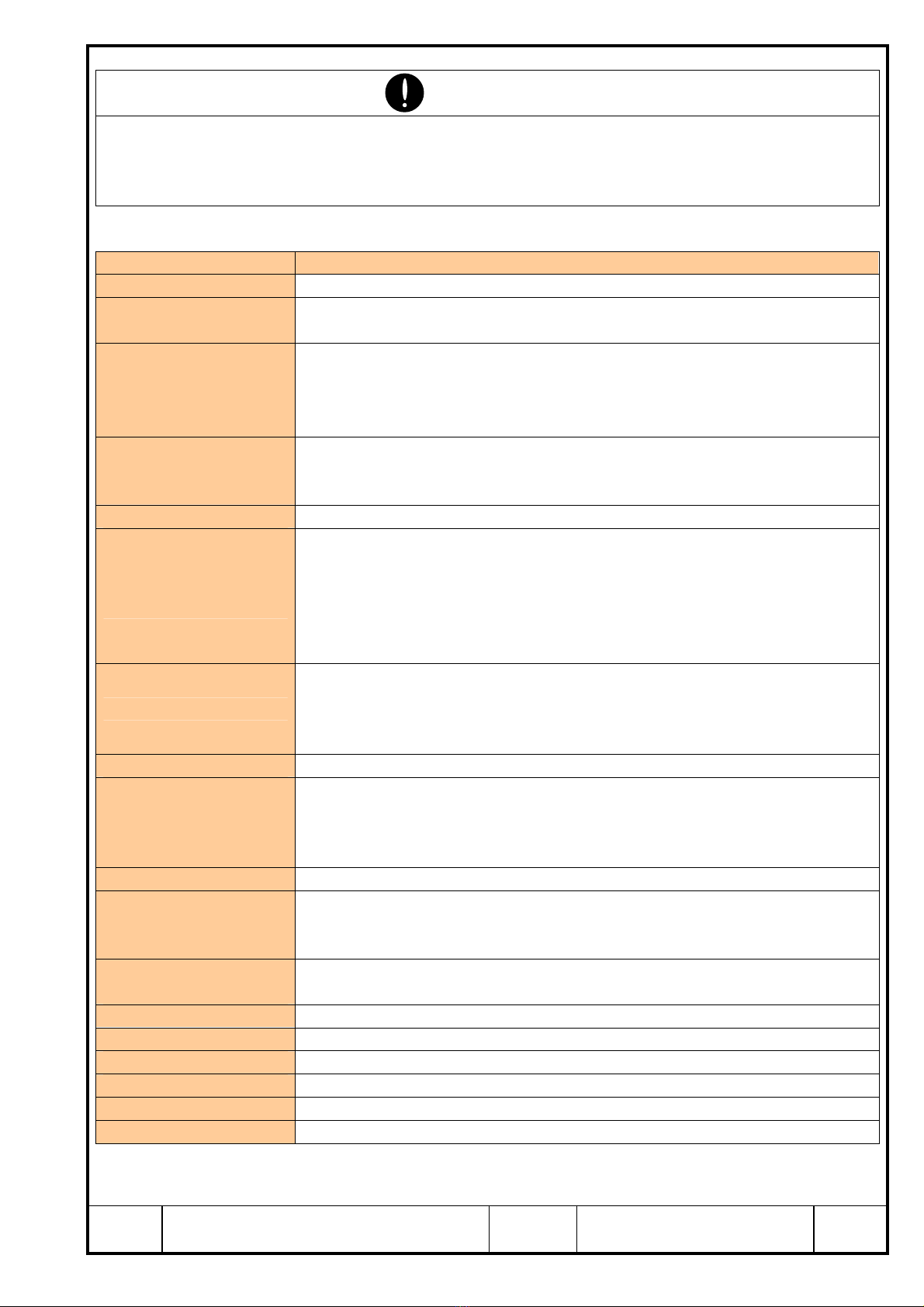
CAUTION
ages
* Be sure to read the instruction manual carefully before servicing this device. Be sure to reach the
instruction manual to final user and be sure to keep the instruction manual by final user.
* This device doesn't operate for approx. 1 sec after putting power source on. Don’t use during this
period.
* Use power source with 2A or more, current capacity. Inrush current flows when putting power
source in. Voltage min. and max. value is 12 to 24VDC.
* Avoid to install at the places where strong light over rated enters into reception part. It may cause
mis-operation.
* It takes approx. 1sec. from releasing emission-stop input to rebooting.
* If 2-scanning mode is used, response time is getting slower.
* If area is changed by outer input, response time is getting slower.
* Min. detectable object is getting larger under mirror reflecting avoidance mode.
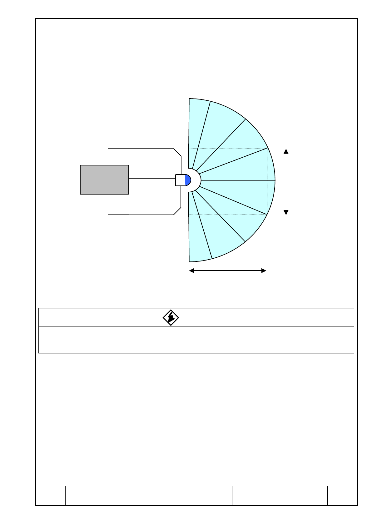
* It can set detecting range up to 10m under within 218 degrees but we can't guarantee it.
* Area from scanning center of sensor to 0.2m is dead zone and it can't detect.
* When installation, don’t close light-projection/reception window or interrupt area.
* If cover is used, use cover with high transparency.
* Response time is delayed under much mutual interference
4
6
6
6
9
9
9
10
13
13
14
14
16
Title Measuring Distance Type Obstacle Detection
Sensor BS-03JN-V01 Instruction Manual
Drawing
No.
C-41-2421 3/19