Holars AVC720 User manual

DigitalVideoRecorder
User Manual
720 V 1.2
Please read this instructions thoroughly before operation and retain it
for future reference.

Thelightningflash with arrowhead symbol, within an equilateraltriangle, is intended toalert
the userto the presence of uninsulated "dangerous voltage" within the product's enclosure that
maybe of sufficient magnitudeto constitute ariskof electric shockto persons.
The exclamation point within an equilateraltriangle is intended to alert theuser to the presence
of important operatingand maintenance-(servicing)instructionsin theliterature accompanying
the appliance.
All the safety and operating instructionsshould be read before operation. The improper operation maycause
permanent damage.
Please usetheprovidedadaptor (Other adaptor is not suitable for this machine).
Please lift andplace this equipment gently.
Donot exposethis equipment to open sunlight.
Donot use this equipmentnear water or in contact with water.
Donot spill liquid ofany kind on the equipment.
Please power off the unit before unplugging.
Donot switch the Power On& Off within short periodof time (within 3 seconds).
Donot attempt to service this equipmentby yourself.
Installation should bemadeby qualified service personnel.
WARNING
1
DVR

2
What do youget
What do youget ?
?
FEATURES ---------------------------------------------------------------- ------------------------
PACKAGE INCLUDING ---------------------------------------------------------------- --------
Before Operation
Before Operation
INSTALLATION GUIDE ---------------------------------------------------------------- --------
FRONTPANEL ---------------------------------------------------------------- -------------------
BACK PANEL ---------------------------------------------------------------- ---------------------
Basic Operation
Basic Operation
STARTTHIS UNIT ---------------------------------------------------------------- ----------------
OPERATION---------------------------------------------------------------- ------------------------
Detailed Menu Setup
Detailed Menu Setup
ACCESS MENU ---------------------------------------------------------------- ------------------
MAIN MENU---------------------------------------------------------------- -----------------------
MENU OPTIONS ---------------------------------------------------------------- -----------------
Advanced Operation
Advanced Operation
OPERATION OPTIONS ---------------------------------------------------------------- --------
KEY LOCK ---------------------------------------------------------------- ------------------------
RS-232 PROTOCOL ---------------------------------------------------------------- ------------
Trouble Shooting ---------------------------------------------------------------- ------------------
Specifications ---------------------------------------------------------------- ----------------------
APPENDIX #1 INSTALLING THE HDD ----------------------------------------------------
APPENDIX #2 PIN CONFIGURATIONS ---------------------------------------------------
APPENDIX #3 RACK MOUNT ----------------------------------------------------------------
APPENDIX #4 RECORDING SPEED -------------------------------------------------------
DVR
TABLE OF CONTENTS
3
3
4
5
7
8
8
10
10
11
14
15
15
15
16
17
19
21
22

FEATURES
DVR Features
Wavelet Compression Formatreplaces Time-Lapse VCR
On ScreenDisplay andRTC (Real time clock) Function
2 Audio inputs / 1Audio outputs (Optional)
4 kinds of recording qualities could be chosen
Alarm Input& Output Function
Video loss records up to 64events
Power-loss memory function
Support 1 Removable HDD, IDE Type
Quick Multiple Search by date/time, alarm, full list
Timer : Schedule recording
Security password protection
RS-232,RS-485communication protocol
3
What do you get ?
Digital Quad Recorder(withHDD cartridge) User Manual
2 Keys for Cartridge Power Adapter and Cord
NOTE : Pleasecheck the package to makesure that you receive the complete accessories which includes those
components shown above.
Accessories pack
PACKAGE INCLUDING

1. Connect camerasand monitor with the DVR.
2. Shown below is one examplefor connecting the DVR to your existing Observation System.
NOTE : The audio inputs/ outputsare optional.
3. Install HDD (The compatibleHDD is over 137GB)
Please refer topage.17 Appendix #1 for installation instructions.
TheHDD must beinstalled beforeturning on the DVR.
4
INSTALLATION GUIDE Before Operation
COMPATIBLE HARD DISK BRANDS
Manufacturer Model Capacity Rotation
HITACHI Deskstar180 GXP(120 GB) 120GB 7200 rpm
HITACHI Deskstar7K250, HDS722516VLAT20 160GB 7200rpm
HITACHI Deskstar7K250, HDS722525VLAT80 250GB 7200rpm
IBM Deskstar120GXP(80GB) 80GB 7200 rpm
IBM Deskstar120GXP(120GB) 120GB 7200 rpm
Maxtor DiamondMax536DX(60GB) 4W060H4 60GB 5400rpm
Maxtor DiamondMaxPlus9 80GB 7200 rpm
Maxtor DiamondMaxPlus9, Model#6Y120L 120GB 7200 rpm
Maxtor DiamondMaxPlus9, Model#6Y160L0 160GB 7200rpm
Seagate BarracudaATAIV, ST380021A 80GB 7200rpm
Seagate BarracudaATAV,ST3120023A 120GB 7200 rpm
Seagate Barracuda7200.7 Plus, ST3160023A 160GB 7200 rpm
WesternDigital CaviarWD1200BB-00CAA1 120GB 7200rpm
WesternDigital CaviarWD2000BB-00DWA0 200GB 7200rpm

1. REMOVABLE HDD CARTRIDGE
Please refer to page.17 Appendix #1.
2. MENU
Press MENU to enter main menu.
3. ENTER
Press ENTER for confirmation.
4. SEARCH
Press SEARCH for searchingrecording video.
5. SLOW
To slow down speed of play mode.
6. REW / Left
REW : Under DVR play mode,it can play video backward atdifferent speeds. (Press REW again toadjust
speed as 1, 2, 4, 8,16,32 times)
Left: Under setupmode, it works as Left button.
7. STOP / Down
STOP : Under DVR Record / Play mode, it can stop themomentaction.
DOWN : Under setupmode, it works as Downbutton.
8. FF / Right
FF : It can play video forward at high speed, and press FF again toadjust speedfrom 1, 2, 4, 8, 16, 32 times.
Right : Under setup mode,it can work as Right button.
9.REC
Press REC to start recording.
10. POWER
Press Power to turnON / OFF theDVR.
5
FRONT PANEL DVR
1
2
3
4
5
6
7
8
9
10
11
12
13

11. PAUSE / Up
Pause: Under DVR play mode, it can pausetheaction.
UP : Under setupmode, it works as Up button.
12. PLAY
Press PLAY to playback recorded video.
13. LED LIGHT
The LED Lightis ON under following condition.
HDD: Blinks on startupafter HDD is activated
HDDFull : HDD is full
ALARM : If Alarm Enable sets as “YES”, while thealarm is triggered , the led will be flashing
TIMER : WhenTimer is set as Enabled
PLAY : On Play mode
REC : On Recordingmode
6

7
1. POWER
Please use theprovided adaptor to connectpower cord (Other adaptor is not suitable for this machine).
2. VIDEO OUT
Connect to the monitor on which the DVR video will be viewed
3. AUDIO IN (R/L) NOTE : THIS FUNCTION IS OPTIONAL.
Connect to audio source, suchas microphone
NOTE : 1.IPS should be set over 30 (for NTSC) or 25 (for PAL)
2.You can record only one Audio source at atime.
AUDIO OUT (R/L) NOTE : THIS FUNCTION IS OPTIONAL.
Connect to monitor or speaker.
with 2 monoaudio outputs from the same source.
4. EXTERNAL I/O
Controlled remotely by an external device or control system.
Alarm input, external I / O explanation.
NOTE : While thepower is off, if the DVR is triggered by Timer or Alarm, it will start recording
automatically and whilestop recording (depend on Alarm Duration Time), the power will
bebackto the “off”status again.
5. VIDEO IN
Connect to a video source, such as acamera, Quador Multiplexer
BACKPANEL DVR

Connect theAC Power Cord with Power Adapter andplug intoan electrical outlet. The red LED indicator light will be
ON and the DVR is in Standby mode.
1.
Press the Power button. The POWER LED will turn from red to orange,and other redLED indicators will turn ON. It
takes approximately 5 to 15 seconds to boot the system with the message: “HDD Detecting ”. Onceconnected, the
POWER LED will changetogreen color, and theAlarm and Timer LED will be ON.
2.
8
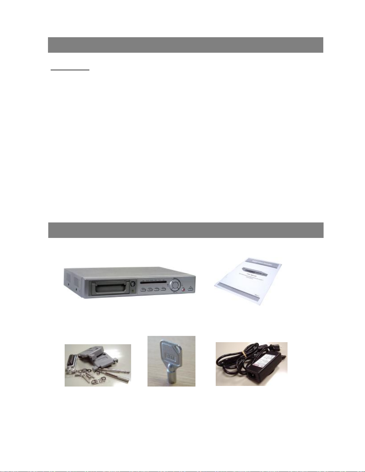
Before using theDVR, pleasehave aHDD installed ready. (refer to Appendix #1 for installation or removal of aHDD).
START THIS UNIT Basic Operation
OPERATION
RECORDING
TheDVR offers a variety ofrecording modes, such as record continuously, at scheduledtime, andbyevents. Youcanset
up recordingspeed andresolution. You canset these options by selecting MENU /RECORD before recording, please
refer to page.12. Under therecording status, if power is off accidentally, recorded videowill stillstore in theHDD. DVR
will returntooriginal recording situation after power returns again.
On the screen, you will find thedate, time, HDD recording type, thesize of available GB left in the HDD memory and the
letter “A”represents themethod of recording that is occurring.
(OW : HDD Overwrite)
NOTE : 1. When the HDD is full under O/W Recording mode,previousrecorded files
may be overwritten without further warning notices.
2. If the HDDs’capacity is only5 GBleft, it will buzz for 3 seconds; so as in4GB, 3GB, 2GB and
1GB. If the O/W Recording mode(NOTE 1) is on, it won’thave thewarning buzzer.
There are4 differentrecordingmodes as followings : Alarm, Timer, Manual and External Record.
1. ALARM RECORD
When DVR is triggeredby an alarm input, it will record immediately. Indicatedby the letter “A”and show!symbol
onthe triggeredchannel.
2. TIMER RECORD
When recording is scheduled by a Timer.Indicated by the letter “T”.
3. MANUAL RECORD
When recording is initiated by manually pressing the REC button. Indicated by the letter “M”.
4. EXTERNAL RECORD
When recording is triggeredby anExternal device. Indicatedby the letter “E”.
2002 JAN 01 01:02:03
AOW
3. Before operating theDVR, pleaseset up thesystem time first. (for settingsystem time, please refer topage.11).
NOTE : When “HDD not found”messagehas been shown up, pleaserefer to appendix# 1. As the HDD is
likely not installedcorrectly.

PLAY
Press “PLAY ”button, theDVR will show the last recording.
1. FAST FORWARD (F.F. ) & FAST REWIND (F.R.)
Youcanincreasethe speed of Fast Forwardand Rewind onthe DVR.
In the Play mode,press ”►► ”once toget 2X speed forward andpress twice to get4X speed,…andthe maximum
speed can reach 32X.
Press ”◄◄ ”once to get 1X speed rewind and press twice to get2X speed, …and the maximum speed canreach
32X.
2. SLOW FORWARD (S.F.) & SLOW REWIND (S.R.)
Youcanalso slow down the speeds of Forward and Rewind on theDVR.
In the Play mode, press the SLOW button and you will enter Slow mode.
Press ”►► ”once to get1/2X speed forwardand press twice to get 1/4X speed,…and theslowest speedcan reach
1/32X.
Press ”◄◄ ”once to get 1/2X speed rewindand press twice to get 1/4X speed, …and the slowest speedcan reach
1/32X.
3. PAUSE
It will let you pausethe current video displayed on thescreen.
4. STOP
Press “STOP ”under any circumstance,it will return DVR tolive monitoring mode.
5. IMAGE JOG DIAL
It will allow you to manually view video frame-by-frame, oneimage at a time.
While in PLAY mode, press “PAUSE ”, it will pause the screen.
Pressing “►► ”buttonadvances the frozenscreen oneimageforward.
Pressing “◄◄ ”button moves back one image.
9

TheMenuallows you toconfigureyour DVR settings. Please follow below
steps to access the Menu :
Press the Menubutton. The password screen will appear: Password: 0000
The default Password is 0000. Simply press theEnter button to access the Menu.
To key-in thePassword, press the “Right”and “Left”buttons to move between numbers, anduse the “Up”
and “Down”buttons toinput thenumber.
Press the ENTER buttononce thecorrect Password is entered. The MENU options screen will appear.
Note: If you get amessage “Password Error”, you haveentered an incorrect password.
There are6 options available in the Main Menu:
TIMER ---------- Scheduling Record
RECORD ------- Record Mode Setup
ALARM---------- Alarm Mode Setup
REMOTE-------- Remote control protocol Setup
SYSTEM -------- System Setup
EVENT ---------- Event List
(MENU)
►TIMER
RECORD
ALARM
REMOTE
SYSTEM
EVENT
10
Outlined below arethebuttons used for Menu setting :
“Up”and “Down”:Scroll up and downor change values when anoption is selected andis blinking
“Left”and “Right”:Scroll sideways within amenuoption thathas beenselected
ENTER : Selects a submenu / an option under a submenu for browsing / modification
MENU : Completes modification of amenu option; exits a menu
ACCESS MENU
MAINMENU
Detailed Menu Setup
NOTE :

MENU OPTIONS
SYSTEM
11
1. BUZZER
While youset theBUZZER as “ON”, it will be triggeredby event occurrence.
3. MESSAGE LATCH
To select whether theDVR messages will disappear after 10
sec or remain on screen.NO is the default setting which the
messages will go away after 10 sec.
4. DATE DISPLAY
To set the Date mode showed on the monitor.
5. DATE
To set the system dateon theDVR.
6. TIME
To set the system time on theDVR.
7. NEW PASSWORD : XXXX (Default password : 0000)
To set the new password.
8. CLEAR HDD
Deleteall thecontents ofyour HDD. When youchoose “YES”on this option, you
will be promptedwith thequestion shown : Press “”to clear HDD or press ”◄”
to confirm not to clear HDD.
10. SYSTEM RESET
Reset all system settings to book to factory default settings.
DVR
2. HDD OVERWRITE
Select “YES”to overwrite previous recording videoin HDD.
NOTE : When the HDDisfull under O/W Recording mode, previousrecorded files
may be overwritten without further warning notices.
(MENU)
TIMER
RECORD
ALARM
REMOTE
►SYSTEM
EVENT
(SYSTEM)
BUZZER : ON
HDD OVERWRITE : NO
MESSAGE LATCH : NO
DATE DISPLAY : Y-M-D
DATE : 2003-JAN-02(THU)
TIME : 01:41:23
NEW PASSWORD : XXXX
CLEAR HDD : NO
SYSTEM RESET : NO
ALL DATA IN HDD
WILL BE CLEARED
ARE YOU SURE?
(◄: NO : YES )

12
TIMER
1. DAY
Select the day,or days of the week (Mon–Fri / Sat-Sun /Daily) thatyou wish to schedule
the DVR toautomatically record.
NOTE : 1.Special Date could be changed by“Enter”, “Up”and “Down”buttons.
2. If you have selected the specific date and recording timer set fromthat specific day to
a newday, then the Recording Timer Schedule will be set as whole week. For specific
date of Recording Timer Schedule, it is not recommended to set End Time over 23:59.
For Example:If you set Timer Schedule Day as Sunday, and START from11:30, but
End on 00:20, then Recording Timer Schedule is set as fromevery Sunday's 11:30 to
next Sunday's 00:20. If you only want to set Recording Timer Schedule fromevery
Sunday 11:30 to Monday 00:20, then you should set Recording Timer Schedule as
Sunday from11:30 to 23:59, and Monday from00:00 to 00:20.
2. START
Select the starting time for the recording.
3. END
Select the finishing time for therecording.
4. IPS
Stand for Images Per Secondand it could let youseeRecord submenu
for moredetails.
NTSC 60、30、15、8、4、2、1、OFF
PAL 50、25、12、6、3、2、1、OFF
5. TIMER ENABLE
Enables / Disables Timer recording function
RECORD
1. RECORD IPS
Select the images per second of recording. The options are as following :
NTSC 60、30、15、8、4、2、1
PAL 50、25、12、6、3、2、1
2. RECORD QUALITY
There are four quality settings : BEST, HIGH, NORMAL and BASIC.
NOTE : Therelationship of Record time, IPS and record quality, please refer to
page.22 Recording Speed.
3. RECORD MODE
Set recording mode between Frame and Field. Oneframe is equal to two fields.
NOTE : It is recommended that you leave the Record Mode as Field.
(TIMER)
DAY START END IPS
DAILY 00:00 00:00 OFF
TIMER ENABLE : YES
(MENU)
►TIMER
RECORD
ALARM
REMOTE
SYSTEM
EVENT
(MENU)
TIMER
►RECORD
ALARM
REMOTE
SYSTEM
EVENT
(RECORD)
RECORD IPS : 60
QUALITY: NORMAL
RECORD MODE : FRAME

ALARM
1. ALARM ENABLE
Enables / Disables Alarm function.
2. ALARM DURATION
Set the length of time for recording after Alarm triggered.
3. RECORD IPS
Select the images per second of recording. The options are as followings :
NTSC 60、30、15、8、4、2、1
PAL 50、25、12、6、3、2、1
4. RECORD QUALITY
There are four quality settings : BEST, HIGH, NORMAL and BASIC.
NOTE : Therelationship of Record time, IPS and record quality, please refer to
page.22 Recording Speed.
5. RECORD MODE
Set recording mode between Frame and Field. Oneframe is equal to two fields.
NOTE : It is recommended that you leave the Record Mode as Field.
13
(MENU)
TIMER
RECORD
►ALARM
REMOTE
SYSTEM
EVENT
(ALARM)
ALARM ENABLE : YES
ALARM DURATION : 10 SEC
RECORD IPS : 60
RECORD QUALITY: HIGH
RECORD MODE : FRAME
REMOTE
1. REMOTE MODE
Select RS-232 or RS-485 interface for theremotecomputer connection
Protocol. (Please refer to page.15for RS-232Remote Protocol)
2. BAUD RATE
Set the speed of the remote computer’s Baud Rate –which is the rate of
Data transmission. Available Baud Rate are 115200, 57600, 19200,9600,
4800, 3600, 2400and 1200.
3. ID
Allow you touse RS-232or RS-485 protocol to program different DVRs.
Therange of ID is from “000”to “255”.
EVENT
Therecordedevents will be showed ona single pageand pleasepress “◄”or “►”to
change the pages. An “Event”occurs when following incidents occur :
PWR : Recovery time after power shut down
in recordmode
HDD : HDD error time
VLS : Video loss time
(MENU)
TIMER
RECORD
ALARM
►REMOTE
SYSTEM
EVENT
(REMOTE)
REMOTE MODE: RS-232
BAUD RATE: 9600
ID: 000
(MENU)
TIMER
RECORD
ALARM
REMOTE
SYSTEM
►EVENT
PWR 2002-JAN-01 03:00:00
VLS 2002-JAN-01 01:02:04
HDD 2002-JAN-01 01:02:03
PWR 2002-JAN-01 01:02:02
VLS 2002-JAN-01 01:02:01
HDD 2002-JAN-01 01:02:00
◄: Page Up : Page Down

SEARCH
1. LAST RECORD
Play thelast recorded video.
2. FULL LIST
Show a listing of all recordedvideo on theHDD which sorted by time.
3. ALARM LIST
Show a listing of all recordedvideo triggered by an Alarm.
NOTE : If there are no Alarm in the record, the screen will
display “EMPTY”.
4. TIME SEARCH
Find video recordedon aspecific datethat is entered.
14
OPERATION OPTIONS Advanced Operation
LASTRECORD
FULL LIST
ALARM LIST
TIME SEARCH
►M 2002-JAN-02 01:02:03
E 2002-JAN-01 05:02:03
A 2002-JAN-01 04:02:03
T2002-JAN-01 03:02:04
T2002-JAN-01 02:02:03
M 2002-JAN-01 01:02:01
◄: PAGE UP : PAGE DOWN
M : Manual Record time
A : Alarm Recordtime
T : Timer Record time
E : External Recordtime

RS-232 REMOTE PROTOCOL
15
KEYLOCK
For added security, you can “Lock”all buttons on your DVR. Locking disables thebuttons andprevents other people from
using the system.
Press ENTER and MENU at thesame time toenable Key Lock.
Press ENTER and MENU at thesame time todisable Key Lock.
You can use thePC keyboard tosimulate DVR keypad.
DATA : REMOTE PROTOCOL using 8 bit data、1 start bit、1stop bit
FUNCTION CODE ASCII FUNCTION CODE ASCII
MENU 0x4D M Down/Stop 0x4E N
ENTER 0x0D ENTER Left/F.F. 0x4C L
Search 0x48 H Right/F.R. 0x52 R
Slow 0x53 S PLAY 0x50 P
Up/Pause 0x55 U RECORD 0x72 r
DVR
TROUBLE SHOOTING
When malfunctionoccurs with DVR, it may be not serious and can be correctedeasily. The table below describes some
typical problems and their solutions. Please check them before calling your DVR dealer.
PROBLEM SOLUTION
lPleaseInsert HDD
lPleaseusetheKey tolock the HDD Cartridge
And press any key
lCheck powercordconnections.
lConfirmthat there ispower at the outlet.
lCheck ifitis underKey Lockmode.
lPress"MENU" & "ENTER" toexist Key Lock mode.
No recordedvideo lCheck iftheHDD is installed properly.
Timer Record enable
does not working lCheck iftheRecord Enableis set toYES
lCheck camera videocable and connections.
lCheck monitorvideocable and connections.
lConfirmthat the camerahas power.
lCheck camera lens setting.
No livevideo
HDD Not Found
No power
Notworkingwhen
press anybutton

SPECIFICATIONS
16
Videoformat NTSC/EIAorPAL/CCIR
Hard diskstorage IDE type, UTMA 66above, 1removableHDDsupported
Record mode Manual/ Alarm/ Timer / External
Playbacksearching Date&Time/ Alarmsearching
RS-232 Yes
Videoinput 1videoinput, composite1Vp-p / 75ohm(BNC)
Videooutput 1videooutput, composite1Vp-p / 75ohm(BNC)
Videoresolution 720 X486(NTSC), 720 X576(PAL)
Videocompression Wavelet
Audioinput Optional
Audiooutput
Optional
VideoLossDetection Yes
RefreshRate 60images/sec. for NTSC/ 50 images/sec. for PAL
Recording Rate 60 images/sec. for NTSC/ 50images/sec. for PAL
KeyLock Yes
Alarm Input TTLinput, Hi(5V), Low(GND)
Alarm Output COM / N.O/ N.C
TimeDisplayFormat
YY/MM/DD, DD/MM/YY, MM/DD/YY, OFF
PowerSource AC90~240V + 10% switching adaptor
PowerConsumption <27W
Operation Temperature 10 ~ 40
On Screen Display Yes
Dimension (mm) 380mm(W)x 270mm(L) x 65mm(H)
NetWeight 5.2kgs
Specifications are subject to change without notice.
DVR

Pleasefollow the steps carefully in order to ensure correct installation.
Thecompartment located onthe frontpanel of theDVR is the removable Cartridge Casing, in which you insert the HDD.The
various parts ofthe Cartridge Casing are labeled for your reference.
2.
17
Removethe Cartridge Casing from the DVR
Removethe Cover from the Cartridge Casing
àUnclip the releaselatch with the word “OPEN”printed beside it by gently pushingon the latch.
àSlide thecover offthe Cartridge Casing.
1.
Cartridge Casing
APPENDIX #1 INSTALLING the HDD
Keyhole
LED indicator lights
Handle
3. Connect theHDD into the CartridgeCasing
Please take theHard Disk Drive and Connect the two cables from the back of the Cartridge Casing to the HDD.

4.
5.
18
Secure the HDDin theCasing (optional)
Use the screws supplied to tighten them, place the HDD intocorrect position.
Slide the top Cover over the Cartridge Casing
Slide theCover forward over the Cartridge Case. Ensure it is secured in place over therelease latch.
6.Reinsert theCartridge Casing into the DVR
Fully insert theCartridgeCaseinto the DVR.
7.Lock the Cabinet
Lock the cabinetby turning the key clockwise.
If you do not lock the cabinet, the DVR system will not function properly.
A (locked)
B
(unlocked)
Note :

APPENDIX #2 PINCONFIGURATIONS
19
25 pin com port
9 pin com port
DQR
Table of contents
Other Holars DVR manuals