de
en
cs
da
es
fi
fr
hr
hu
it
lt
nl
pl
pt
ro
ru
sl
sv
zh
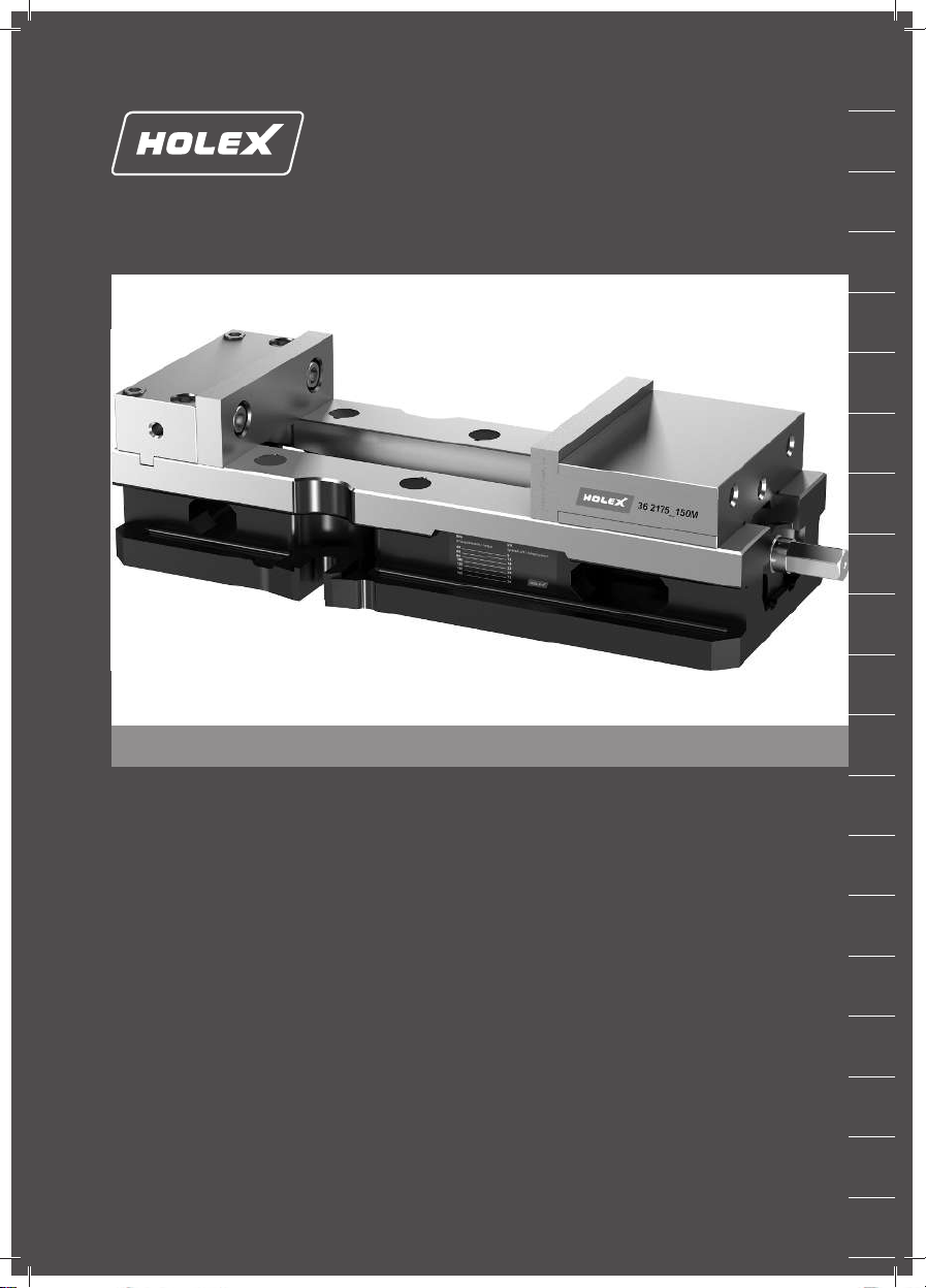
HOLEX Maschinenschraubstock
3.3. SACHWIDRIGER EINSATZ
Nicht in explosionsgefährdeten Bereichen verwenden.
Nicht in Bereichen mit hohem Staubanteil, brennbaren Gasen, Dämpfen oder Lösungsmitteln verwenden.
Keine Montage von Komponenten, die nicht den Spezifikationen entsprechen.
Keine eigenmächtigen Umbauten vornehmen.
Nur originale Ersatz- und Verschleißteile verwenden.
Nicht außerhalb der Betriebsparameter betreiben.
3.4. PERSÖNLICHE SCHUTZAUSRÜSTUNG
Nationale und regionale Vorschriften zur Sicherheit und Unfallverhütung beachten. Schutzkleidung muss entsprechend der
bei der jeweiligen Tätigkeit zu erwartenden Risiken gewählt, bereitgestellt und getragen werden.
3.5. PERSONENQUALIFIKATION
Fachkraft für mechanische Arbeiten
Fachkraft im Sinne dieser Dokumentation sind Personen, die mit Aufbau, mechanischer Installation, Inbetriebnahme, Stö-
rungsbehebung und Wartung des Produkts vertraut sind und über folgende Qualifikationen verfügen:
Qualifizierung / Ausbildung im Bereich Mechanik gemäß den national geltenden Vorschriften.
Unterwiesene Person
Unterwiesene Personen im Sinne dieser Dokumentation sind Personen, die für die Durchführung von Arbeiten in den Berei-
chen Transport, Lagerung und Betrieb unterwiesen worden sind.
3.6. BETREIBERPFLICHTEN
Der Betreiber muss sicherstellen, dass Personen, die am Produkt arbeiten, die Vorschriften und Bestimmungen sowie fol-
gende Hinweise beachten:
Nationale und regionale Vorschriften für Sicherheit, Unfallverhütung und Umweltschutzvorschriften.
Keine beschädigten Produkte montieren, installieren oder in Betrieb nehmen.
Erforderliche Schutzausrüstung muss bereitgestellt werden.
Überwachen der Funktionen des Maschinenschraubstocks durch den Bediener.
Keinen Betrieb ohne regelmäßige Wartung durchführen.
In Handhabung des Maschinenschraubstocks eingewiesen und geschult werden.
Maschinenschraubstock mit ausreichender Beleuchtung aufstellen und betreiben.
Regelmäßige Reinigung durch den Bediener durchführen.
Wartungs- und Instandhaltungsarbeiten sowie Störungsbeseitigung durch das Instandhaltungspersonal.
3.7. SCHUTZEINRICHTUNGEN
Schutzeinrichtungen an Maschine, in welcher das Spannmittel verbaut ist, vor jeder Verwendung auf Funktionsfähigkeit
prüfen. Maschine gegen unbeabsichtigtes Wiedereinschalten sichern. Auf sachgerechte Montage des Spannmittels achten.
Schutzeinrichtungen nur nach vollständigem Stillstand der Maschine entfernen.
Bei drohender Gefahr oder Unfall NOT-HALT an Maschine betätigen.
Bei allen Reinigungs-, Wartungs- und Reparaturarbeiten muss sich Maschine im NOT-HALT befinden.
4. Produktbeschreibung
Maschinenschraubstock mit bewegliche Spannbacken für Befestigung von Werkstücken auf Maschinen zur Weiterbear-
beitung.
5. Geräteübersicht
Stationäre Spannbacke
Bewegliche Spannbacke
Antrieb mit Spindel
Fuß
Gehäuse
6