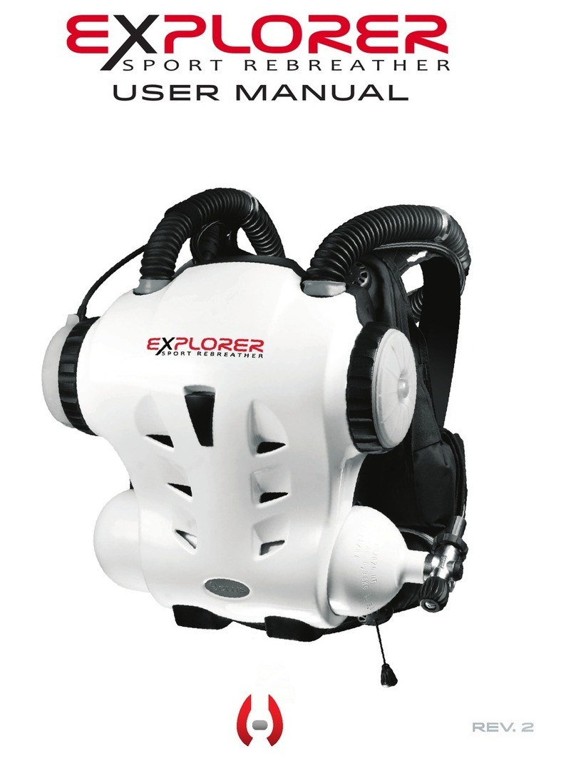
Hollis Explorer User manual

NO LIMIT
user Manual
REV.6

DANGERS, WARNINGS, CAUTIONS, AND NOTES
Pay attention to the following symbols when they appear throughout this docu-
ment. They denote important information and tips.
This is the operations manual for the
HOLLIS EXPLORER
U.S.patents have been applied for; patents pending.
This manual, specifications and features of the Explorer are proprietary and
copyright Hollis Inc., 2012.
This document cannot be copied or distributed without the prior agreement and
authorization from Hollis Inc.
All information contained is subject to change. Contact the manufacturer for the
latest information. www.hollisgear.com
The EXPLORER is manufactured in the USA by Hollis Inc.,
2002 Davis Street, San Leandro, CA 94577. USA
Ph (510) 729-5100
EC Type approved by SGS UK Ltd. Weston-super-Mare. BS22 6WA. Notified
Body No. 0120.
Testing conducted by ANSTI Test Systems. Hants.
To ensure your user information is up to date. Please check
www.hollisgear.com/support.asp for updates to this manual.
For warranty information see www.hollisgear.com/support_warranty.asp
!DANGERS:are indicators of important information that if ignored would
lead to severe injury or death.
!WARNINGS: are indicators of important information that if ignored could
lead to severe injury or death.
!CAUTIONS: are indicators of information that if ignored may lead to minor
to moderate injury.
!NOTES: indicate tips and advice that can inform of features, aid assembly,
or prevent damage to the product.

!WARNING:
Use of The Explorer manual
This user manual does not, nor is it intended to
contain any information needed to safely dive with
any type of SCUBA apparatus. It is designed as a
guide for the proper setup, operation, maintenance,
and field service of the Hollis Explorer only. It does
NOT take the place of a recognized training agency
instructor-led diver-training course or its associated
training manual(s) and materials. This user manual
is intended to be used only as a type specific ad-
dition to such training and materials, and as a user
reference. This manual cannot be used as a sub-
stitute guide for any other type of Self Contained
Underwater Breathing Apparatus (SCUBA).
EXPLORER DESIGN TEAM
Bob Hollis
Kevin Gurr
HollisExplorer
User Manual
Document Control Number: 12-4102
Rev. 6
Publish Date: 6/17/2014
Photo by:
www.HINDL.com

ii |
!WARNING:
GENERAL SAFETY
No person should breathe from, or attempt to operate in any way, a Hollis Explorer rebreather, or any
component part thereof, without first completing an appropriate Hollis Certified user-training course.
Further, no Explorer diver should use a Hollis Explorer without direct Hollis instructor supervision until
they have mastered the proper set-up and operation of the Hollis Explorer rebreather. This includes
new Explorer divers as well as Explorer certified divers who have been away from diving for an extend-
ed period of time and would benefit from an instructor-led refresher course to regain skills and mastery
of the Hollis Explorer. Failure to do so can lead to serious injury or death.
!WARNING:
NITROX STATEMENT
The EXPLORER equipment is classified as being suitable for use with nitrogen-oxygen (Nitrox) breath-
ing gas mixtures containing up to 40% oxygen by volume without the need for special preparation,
cleaning, or component parts.
If Explorer equipment is subsequently used with equipment, or connected to an air supply system, that
is not rated for Oxygen Service, it can subsequently be used with Nitrox (32 - 40% O2) as long as the
equipment is maintained in accordance with the procedures and parts specified by Hollis.
The EXPLORER was designed for use with Nitrox (32 - 40% O2). DO NOT use gas mixtures with a
fraction of oxygen greater than 40% with your EXPLORER.
!WARNING:
CAUSTIC MATERIAL
The CO2absorbent used in the scrubber is caustic alkaline material. Take steps to protect yourself from
direct lung and skin contact. Furthermore, poor management of the breathing loop could lead to water
contact with the CO2absorbent, causing a “caustic cocktail” (very caustic liquid). This could lead to se-
vere chemical burns and if inhaled - possible drowning. Proper handling procedures, pre-dive checks,
dive techniques, and maintenance mitigates this risk.
GENERAL SAFETY
STATEMENTS + WARNINGS

| iii
!WARNING:
BATTERY WARNING
The Explorer relies on batteries to maintain a safe breathing gas content. Never dive the Explorer
without a sufficient charge on the rechargeable batteries. See "Batteries" PART 2 Section 1 for further
details.
!WARNING:
DESIGN AND TESTING
The Hollis Explorer has been designed and tested, both in materials and function to operate safely
and consistently under a wide range of diving environments. You must not alter, add, remove, or re-
shape any functional item of the Hollis Explorer. Additionally, NEVER substitute any part of the Hollis
Explorer with third-party items which have not been tested and approved by Hollis for use with the
Explorer.
This includes, but is not limited to, hoses, breathing assemblies, electronics, breathing gas delivery
assemblies and their constituent parts, sealing rings, valves and their constituent parts and sealing
surfaces, latches, buoyancy devices, inflation and deflation mechanisms and onboard alternate
breathing devices.
Altering, adding, removing, re-shaping or substituting any part of the Hollis Explorer with non-ap-
proved parts can adversely alter the breathing, gas delivery or CO2absorption characteristics of the
Hollis Explorer and may create a very unpredictable and dangerous breathing device, possibly lead-
ing to serious injury or death.
Non-approved alterations to functional parts of the Explorer will automatically void all factory war-
ranties, and no repairs or service work will be performed by any Hollis service professional until the
altered Explorer unit is brought back into factory specifications by a Hollis service professional at the
owner’s expense.
!WARNING:
COMPUTER / CONTROLLER-SPECIFIC WARNINGS
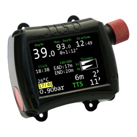
This computer is capable of calculating deco stop requirements. These calculations are predictions of
physiological decompression requirements. Calculations are for contingency use only. The Explorer
in this “sport” configuration is not intended for decompression use.
iv |
!WARNING:
HYPERCAPNIA, HYPOXIA, & HYPEROXIA RISKS
This device is designed to maintain a safe breathing gas under sport diving conditions. But like all
machines it could fail. To mitigate risks, it is essential that a diver is trained and fully understands the
risks of hypercapnia (CO2poisoning), hypoxia (oxygen starvation), and hyperoxia (oxygen poisoning).
It is also critical to have adequate bailout gas for the planned depth.
Be aware that a well packed and well maintained Scrubber is key in achieving a life-support system.
The Canister Duration Meter (CDM) is not a substitute for good system maintenance and Pre-Dive
checks. Always use your training and discipline to ensure the sub-systems in the EXPLORER are oper-
ating correctly.
Critical components and potential failures are:
- The scrubber seal around the scrubber
- A poorly packed scrubber
- Used or out of date scrubber material
Proper training and education are your best insurance against an inconvenient situation becoming a
deadly one.
!WARNING:
ALTITUDE
For the Explorer to accurately gauge altitude and the preceding dive depths, the Explorer must be
turned on prior to diving. Additionally, diving at high altitude requires special knowledge of the varia-
tions imposed upon divers, their activities, and their equipment by the decrease in atmospheric pres-
sures. Hollis recommends completion of a specialized Altitude training course by a recognized training
agency prior to diving in high altitude lakes or rivers.

| v
!WARNING:
COLD WATER
Diving rebreathers in frigid water requires special equipment, training, and preparation to prevent pos-
sible injury or death. Rebreathers present unique variables to cold water diving that are not a factor in
open circuit diving in the same temperatures. Cold water diving is beyond the scope of this manual.
There are many variables not listed here. It is essential and the responsibility of the diver to be aware
of all issues. The diver must know how to best prepare their equipment, and how to best prepare
themselves for the cold water environment. The diver must obtain further training beyond standard
Explorer training or Open Circuit Ice Diver certification alone.
Cold Water Issues Include The Following:
- Changes in temperature may lead to expansion and contraction of CO2absorbent material possibly
leading to channeling.
- Decreases in temperature effect the efficiency of the scrubber and greatly reduce the rated use
times.
- Sensors are sensitive to extreme temperatures. Storage of Oxygen Sensors below 32° F (0°) or
above 100° F (37.8° C) can damage or greatly shorten the life of the sensor.
- Mushroom valves may freeze open or closed if condensation is allowed to cool. Always perform the
Pre-Dive Sequence and pre-breathe the unit before entering the water and before any subsequent
dives. The diver should warm and visually inspect the mushroom valves between dives.
- Open circuit bailout must be rated and compatible with the environments dived in.
- Check the scrubber MSDS (Material Safety Data Sheet) for specific warnings about storage tem-
peratures. Scrubber material should not be allowed to freeze inside or outside of the rebreather.

vi |
TABLE OF CONTENTS
General Safety Statements & Warnings
PART 1
YOUR NEW EXPLORER
SECTION 1
REBREATHER LIFE SUPPORT SYSTEM
RULES
SECTION 2
GAS FLOW
SECTION 3
MECHANICAL FEATURES
PART 2
UNPACKING YOUR NEW
EXPLORER
SECTION 1
BATTERIES
SECTION 2
INITIAL ASSEMBLY
SECTION 3
COMPLETE DISASSEMBLY & REASSEMBL
PART 3
LIFE SUPPORT SYSTEM
(COMPUTER)
SECTION 1
GENERAL OPS
SECTION 2
AUTOMATIC TURN ON
SECTION 3
DISPLAY SYMBOLS
SECTION 4
SCREEN ICONS
SECTION 5
DIVE SCREENS
SECTION 6
STATUS SCREENS
SECTION 7
MAIN MENU
SECTION 8
SETUP MENU
ii-vii
2
3
4
7
8
11
19
24
25
26
27
28
29
31
33
34
36
37
42
44
49
52
61
62
63
64
65
66
71
75
82
SECTION 9
BAILOUT & GAS CONFIGURATION
SECTION 10
DCP (DIVE CONTROL PARAMETER)
SECTION 11
RMS(RESOURCES MANAGEMENT SYSTEM)
SECTION 12
O2SENSOR CALIBRATION
SECTION 13
O2SENSOR VOTING
SECTION 14
CDM (CANISTER DURATION METER)
SECTION 15
DISPLAY & ALARM SYSTEMS
SECTION 16
ALARM FLOW DIAGRAMS
SECTION 17
GAS RESERVES
SECTION 18
MOD (MAXIMUM OPERATING DEPTH)
SECTION 19
DIVING AT ALTITUDE
SECTION 20
DECO CONTINGENCY
SECTION 21
INTERNET REPROGRAMMING
PART 4
GETTING READY TO DIVE
SECTION 1
GEAR PREP
SECTION 2
CO2ABSORBENT SCRUBBER PACK
SECTION 3
PRE-DIVE SETUP
PART 5
POST DIVE
SECTION 1
DAILY MAINTENANCE

PART 6
MANDATORY DIVING SKILLS
SECTION 1
EXPLORER BASICS
SECTION 2
IN-WATER SKILLS CHART
SECTION 3
EXPLORER SKILLS COMPLETED
PART 7
LONG TERM MAINTENANCE &
SERVICE
SECTION 1
O2 SENSORS
SECTION 2
SERVICE
SECTION 3
MAINTENANCE SCHEDULE
PART 8
APPROVED PRODUCTS &
GLOSSARY
SECTION 1
APPROVED PRODUCTS
SECTION 2
GLOSSARY
84
87
91
92
94
95
97
98
| vii

2 |
Your New Explorer
Rebreather LifE Support
System Rules
!DANGER: Read and understand this list prior to using this unit.
If you do not understand any or all of this section please contact
your training agency or Hollis.
Rules for EXPLORER Diving
1. Always complete all pre-dive checks. Pay special attention to BOV
mushroom valve tests.
2. Always pre-breathe the Explorer until the system passes its’ tests.
3. Do not modify the Explorer without the manufacturer’s written consent.
4. Do not use a full-face mask, unless approved by Hollis for use with the
Explorer.
5. Always analyze your gas.
6. Never dive a unit you suspect is leaking and has not passed all the pre-
dive tests.
7. Never leave your BOV open on the surface.
8. Ensure your BC is inflated at the surface.
9. Take time to adjust your weight correctly, do not dive over-weighted.
10. Always dive with buoyancy control and buoyancy inflation.
11. Practice a skill on every dive.
12. Avoid unnecessary mask clearing.
13. Regularly sanitize the unit.
14. Never exceed the CO2alarms.
15. Never hold your breath.
16. Never start a dive with a low battery alarm.
17. Always carry bailout gases of sufficient volume for the planned dive as
per your training agency recommendations.
IF IN DOUBT BAIL OUT!
1.1

| 3
GAS FLOW
As the diver exhales gas flows through the hose (blue arrow) and over the
right shoulder. It then enters the absorbent scrubber and flows across the
Oxygen and CO2sensors in the Sensor Module and through the inhale
hose (red arrow) and back to the mouthpiece.
Gas also naturally flows in and out of the exhale and inhale counterlungs.
BOV
(Bail Out Valve)
Scrubber
Pack
“In - Out”
Indicator
Exhale
Counterlung
Inhale
Counterlung
Electronics
O2& CO2
Sensors
Absorbent
Scrubber
1.2

4 |
Mechanical Features
The EXPLORER is an electro-mechanical rebreather. Over time certain
software, hardware, optional extras, and/or software upgrades will become
available. Please check www.HollisGear.com for details.
HARNESS/BCD
EXPLORER uses a custom bolt fitting, backplate, Solo webbing harness,
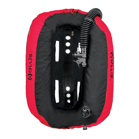
and Hollis C45LX Wing. There is an optional EXPLORER BCD available.
COUNTERLUNG
The EXPLORER comes complete with dual back-mounted counterlungs
(BMCL). These are attached to the canister by a screw threaded O-ring
fitting.
CYLINDER
EXPLORER uses a 5L/40cuft cylinder with a nitrox compatible inline valve.
Dives over 18 m/60 ft requires that an additional bailout cylinder of a
minimum capacity of 3 L/20 cuft be used in conjunction with the 5L/40 cuft
cylinder.
!NOTE: All calculations presented in this manual assume the use of
a 5 L/40 cuft cylinder.
USA Only Cylinder Options Chart
Capacity Working pressure
Manufacturer WC (L) WC (CU/FT) BAR PSI
Any brand that is
prepped for nitrox use.
Typical sizes and pres-
sures are shown.
5 41 232 3410
4.9 40 204 3000
4.3 35.26 204 3000
5 41 232 3410
6 49 232 3410
!NOTE: The Explorer can accomadate a maximum 14 cm/5.5 in
diameter tank.

| 5
CC
OC
Fig. 1.1
EU Only Cylinder Chart
Capacity Working pressure
Manufacturer WC (L) WC (CU/FT) BAR PSI
Any CE approved 5 41 232 3410
OUTER CASE
The outer case is made from high impact plastic.
OVER-PRESSURE VALVES
EXPLORER uses a combined water release and balanced Loop Control
Valve (LCV). The balanced valve ensures that the underwater release
pressure is near constant in any orientation. When the unit vents, it also
removes any water from the exhale counterlung. Water removal is best
conducted in a heads up position.
In addition to the LCV there is a master (high flow) over pressure release
valve that is set to 40 mbar to help control ascents.
BOV (BAILOUT VALVE)
EXPLORER comes with a BOV. The BOV is supplied by the onboard nitrox
tank. The BOV is designed as the primary bail out (providing a sufficient/
planned volume is carried).
The BOV has two modes (Fig. 1.1):
• OC (Open Circuit Position)
• CC (Closed Circuit Position)
When the BOV is open, the BOV is in the closed circuit position and when
the BOV is closed it is in the open circuit position.
INTELLIGENT HUD (HEADS UP DISPLAY) & BUD (BUDDY UNIVERSAL
DISPLAY)
The Intelligent HUD (Heads Up Display) is attached to the BOV in the
divers line of sight. There is also a BUD (Buddy Universal Display) in the
EXPLORER LSS Module for Dive Buddy/Instructor use.
1.3

6 |
These displays give full alarm status at all times using a visual and a tactile
alarm system.
SENSORS
The EXPLORER uses 3 oxygen sensors and a wireless HP sensor. It can
also be equipped with an optional gaseous CO2sensor.
All sensors are automatically calibrated by the electronic control system.

| 7
unpacking your new explorer
Batteries
The EXPLORER uses Lithium Polymer batteries. These rechargeable bat-
teries are very efficient and provide many years of reliable operation.
Rechargeable Lithium batteries can be recharged at any time and do not
have a significant memory affect, which would otherwise cause unreliable
battery operation. The batteries are UL listed (flight safe) and are double
sealed to reduce the chance of leakage to a minimum.
As extra confidence, the LSS Module battery pack includes 3 separate
batteries to ensure operation even under multiple battery failure scenarios.
During diving, the battery reserve alarm will indicate when there is still suf-
ficient battery to allow a return to the surface with a small reserve. The LSS
MUST then be charged prior to diving again.
The handset has its own battery which is automatically charged from the
EXPLORER LSS module.
The user should keep the batteries fully charged to ensure there is always
maximum battery charge for any dive. Additionally, the Optocon protective
cap should be installed when the Explorer is not being charged.
A fully charged battery pack will display 900 minutes of battery life on the
wrist display. See PART 3 Section 6 for directions on how to access the
Battery Status Screen.
!DANGER: The battery estimate is based on many variables. Chang-
es in conditions (i.e. cold water) may shorten charge times. Plan
dives accordingly, and always monitor the HUD and Wrist Displays
for system operation status.
!NOTE: The EXPLORER must be fully charged before its rst use.
!CAUTION: Always ensure the Optocon charge connector is dry
before attaching the charging connector. Damage may result if
this is not done.
Check that all parts of the charger are kept dry and only used indoors.
Battery level alarms will activate when the batteries get low and will be
displayed on the Status screen.
!WARNING: DO NOT dive with a battery level, that is less than twice
your expected dive time for the next dive.
!NOTE: The battery discharges at a faster rate when the Sensor
Module is separated from the LSS.
2.1

8 |
Fig. 2.1
Initial Assembly
INTRODUCTION
Your Explorer is assembled and tested at the factory. Some components
are then removed to package the unit. When you receive your Explorer, the
following components will need to be put together.
GENERAL NOTES ON ASSEMBLY
1. All O-rings should be lightly lubricated.
2. Inspect all O-rings for cracks and other damage during each assembly.
3. All breathing loop parts should be sanitized before diving. If assembling
for a dive, see the following section "Complete Disassembly and Reassem-
bly" for further instructions.
Step 1. Remove all parts from the split top box (Fig. 2.1).
Step 2. Open the Oxygen sensor and CO2sensor (optional) boxes. Re-
move the sensors from their boxes, and open up the airtight bags.
!DANGER: Only Hollis Explorer Oxygen sensors must be used with
this unit. No other sensors are tested or approved. These are avail-
able from your Hollis Dealer.
!DANGER: All oxygen sensors must be allowed to sit in an AIR at-
mosphere for at least 24 hours prior to use in the EXPLORER. The
Sensors can be immediately assembled into the Sensor Module but
this module should not be fully installed for at least 24 hours after
unsealing the sensors packages.
!WARNING: The sensors must be calibrated after the 24 hour accli-
mation period.
Step 3. Pull the Sensor Module straight out of the Canister.
Step 4. Push the three oxygen sensors onto their respective connection
points as shown in the picture (Fig. 2.2).
!NOTE: Ensure the oxygen sensors are installed with the white
membrane facing up, as shown.
Fig. 2.2

| 9
Step 5. If using the optional CO2sensor accessory (part # 240.9001),
install now.
!WARNING: Before use, it is essential that you read and understand
all maintenance and use information for the CO2sensor and cap.
See the Explorer CO2Sensor User Manual, doc. # 12-4127 (available
at http://www.hollis.com/support/manuals).
!DANGER: ONLY the Hollis CO2sensor may be used with this unit.
No other CO2sensors are tested or approved.
Step 6. Reinstall the Sensor Module.
Step 7. Undo the rubber latches at the base of the Case Front/Back as-
sembly and lift up the Case Back until the hinge at the top is free (Fig. 2.3).
Place to one side.
Step 8. Inside the Explorer case you will find a zippered case containing
the LSS (Life Support System). Remove the LSS from its case. Unscrew
the Optocon charging/download connector protection cap.
Plug in the the power charger. You will need to rotate the cable end con-
nector until the key way aligns. Then push it in and tighten the black lock
ring clockwise (Fig. 2.4). The lock ring will spin freely once the connector
is fully assembled. Once connected and power is applied, a red light will
appear on the LSS module.
When charging, a Red light appears on the LSS Module. It turns Green
when the LSS Module if fully charged. A full charge takes approximately 10
hours.
!NOTE: The Explorer could take up to 30 minutes for the red indica-
tor light to illuminate if the battery has been completely drained.
EXPLORER has 3 battery status displays with the charger connected:
1. Battery Charging (Empty) (Fig. 2.5)
2. Battery Charging (Fig. 2.6)
3. Battery Charged (Fig. 2.7)
To remove the optocon charger, unscrew the ring (which will rotate freely
until pulled back to start the thread) and pull out the connector. Reinstall
the Optocon charging/download connector protection cap.
!CAUTION: To avoid damage, the Optocon charging/download
connector protection cap should be installed when not charging/
downloading your Explorer.
Fig. 2.3
2.2
Fig. 2.5
Fig. 2.6
Fig. 2.4
Fig. 2.7

10 |
Step 9. Once the LSS Module is charged, it may be installed on the inha-
lation side of the Explorer canister. First inspect the O-rings and sealing
surfaces to ensure they are in good condition. The Explorer case has
two notches on either side of the canister opening. Align the locking ring
tab with the notch on the left side, when the Explorer case is laying on
the harness side. Additionally, line up the solenoid, as shown (Fig. 2.8).
Then while pressing the LSS assembly into position, turn the the lock ring
clockwise 180 degrees until the tab rests in the other notch on the Explor-
er case.
Step 10. Adjust the included Harness or optional BCD for proper fit.
!NOTE: See the Hollis Buoyancy Guide (doc. 12-4012) for instruc-
tions on the Harness and Wing ttment and proper use. It may be
downloaded from http://hollisgear.com/support_manuals.asp.
Step 11. Inspect the mushroom valves in the BOV and make sure they are
in place.
!DANGER: Your Explorer must have proper mushroom valve func-
tion before every dive. See ‘BOV Assembly’ subsection in the
"Complete Disassembly & Reassembly" PART 2 Section 3 of this
manual for instructions on testing the mushroom valves.
Attach the regulator LP hose to the BOV and gently tighten the nut to the
hose inlet (Fig. 2.9, item C). After inspecting the hose end O-rings, attach
the breathing hoses to the BOV. Ensure the white hose end goes to the
inhale side (Fig. 2.9, item B) of the BOV.
Attach the HUD Bracket to the inhalation side hose nut and snap the HUD
into the HUD Bracket (Fig. 2.10). The HUD Bracket is secured with an
O-ring attached to the two tabs on the underside of the bracket.
Step 12. Ensure the counterlungs are correctly positioned where they will
not get pinched, cut, or unecessarily restricted (Fig. 2.11). Then refit the
Case Back and secure the two clips at its base (Fig. 2.12).
!WARNING: Ensure that the counterlungs are not pinched during in-
stallation of the Case Back. Pinching counterlungs could puncture
or cut the counterlungs, leading to ooding and risk of drowning.
!NOTE: The Case Back will not t or lock properly if the end cap
lock rings are not in the correct orientation.
Fig. 2.8
Fig. 2.12
Fig. 2.9
A B
C
Fig. 2.11
Fig. 2.10

| 11
Complete Disassembly & Reassembly
INTRODUCTION
The information below will enable complete disassembly, cleaning, rebuild-
ing, and testing of the EXPLORER Rebreather. Further disassembly must
be performed by a qualified Hollis EXPLORER Technician.
GENERAL NOTES ON ASSEMBLY
1. All O-rings should be lightly lubricated.
2. Inspect all O-rings for cracks and other damage during each assembly.
3. Sanitize all breathing loop parts.
!DANGER: Only Hollis Explorer Oxygen sensors must be used with
this unit. No other sensors are tested or approved. These are avail-
able from your Hollis Dealer.
!DANGER: ONLY the Hollis CO2sensor may be used with this unit.
No other CO2sensors are tested or approved.
!WARNING: All servicing beyond the user level must be performed
by an approved Explorer service technician at a Hollis service
facility.
BOV DISASSEMBLY
There are very few parts within the BOV assembly that should be removed
by the user; since many parts (especially the second stage components)
require additional setup by a trained Explorer technician.
• Turning counterclockwise, unscrew the breathing hose ends.
• Remove and inspect the hose end O-rings for damage.
• Using the rubberized end of a pencil or other blunt/soft instrument, insert
the pencil through one of the mushroom valve carriers (moving the mush-
room valve aside first) and gently push out the opposite carrier assembly.
!NOTE: DO NOT push on the center of the carrier. ONLY push on
the outer edge.
• Remove the mushroom valve carrier O-rings (Fig. 2.13).
• Gently pull out the mushroom valve (Fig. 2.14).
Fig. 2.13
Fig. 2.14
2.3

12 |
BOV REASSEMBLY & CARE
• Clean the mushroom valve carrier O-ring and the groove around the
mushroom valve carriers. Lightly lubricate and refit new O-rings.
• Inspect the mushroom valve and mushroom valve carrier for damage.
Sanitize and remove any debris from the carrier.
• Clean the mushroom valve carrier O-ring and the groove around the
mushroom valve carriers. Lightly lubricate and refit the O-rings.
• Refit the mushroom valves to the carriers.
!DANGER: DO NOT put lubricant on the mushroom valves.
• Having cleaned and sanitized the BOV; press the valve carriers into the
BOV. Ensure the O-rings around the mushroom valve carriers have not
extruded out of their grooves.
! DANGER: Check the ow in the BOV. It should be from the diver's
left to diver's right (with the mouthpiece in the diver's mouth) (Fig.
2.15).
• Inspect and clean the rubber mouthpiece. Ensure there are no pin holes
or tears. Refit with a new cable tie, and tighten. Carefully, remove sharp
edges from the cable tie.
BOV PRIMARY TEST
In closed circuit mode, block the right hand (exhale) side and blow (do not
apply excessive force) into the mouthpiece. The inhale (diver's left side)
mushroom valve should seal and no gas should exit out of the second
stage exhaust or the front diaphragm.
Faults:
• Mushroom valve (inhale side) leak. Remove the carrier and inspect the
mushroom valve and O-ring. Replace as needed.
• BOV barrel O-ring or activation handle O-ring leak. Replace O-ring.
Fig. 2.15
Other manuals for Explorer
1
Table of contents
Other Hollis Diving Instrument manuals

Hollis
Hollis DG05 User manual

Hollis
Hollis Prism 2 User manual

Hollis
Hollis HD200 BCD User manual

Hollis
Hollis Katana Sidemount Harness User manual

Hollis
Hollis LED-5 Manual

Hollis
Hollis DG03 User manual

Hollis
Hollis Prism 2 User manual

Hollis
Hollis Prism 2 User manual

Hollis
Hollis LX Wing Series User manual

Hollis
Hollis Explorer User manual
Popular Diving Instrument manuals by other brands

Cressi-sub
Cressi-sub 2nd Stage Ellipse Balanced Repair and maintenance instructions

Gravity Zero
Gravity Zero MK II user manual

Zeagle
Zeagle 1BCD owner's manual

Dive Gear Express
Dive Gear Express DGX Xtra First Stage Service manual

Oceanic
Oceanic BioDry Suit owner's guide

BARE
BARE Buoyancy Compensator manual