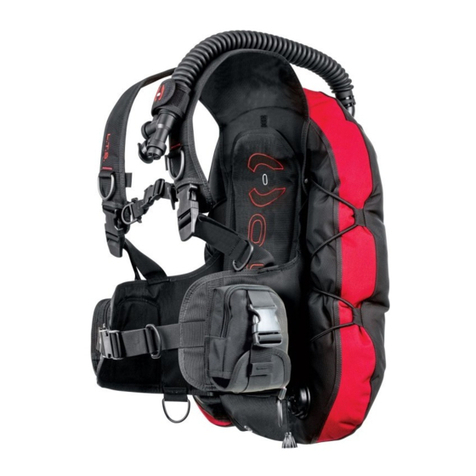
Hollis LTS Series User manual

1
HOLLIS
1540 North 2200 West
Salt Lake City,
Utah 84116
USA
888-270-8595
www.Hollis.com
©2018 Hollis. All rights reserved.
Doc. No. HO.02.05.0009 (5/24/18)
BC MANUAL

2
This Hollis BC Owners Manual is copyrighted and all rights are reserved. It may not, in whole or
in part, be copied, photocopied, reproduced, translated, or reduced to any electronic medium or
machine-readable form without prior consent in writing from Hollis.
Hollis BCD Owners Manual Doc. # HO.02.05.0009
© Hollis, 2018
Salt Lake City, UT USA 84116
888-270-8595
TRADEMARK, TRADE NAME, AND SERVICE MARK NOTICE
Hollis and the Hollis logo are registered or unregistered trademarks of Hollis. All rights are reserved.
PATENT NOTICE
U.S. Patents have been issued, or applied for, to protect the following design features: Backpack
Systems (U.S. Patent No. 5,378,084, Gas Impermeable Laminate (U.S. Patent No. 5,693,412),
Harness Buckle (U.S. Patent No. D409,114), Weight Drop System (U.S. Patent No. 5,218,745), Soft
Backpack (U.S. Patent No. 4,952,095), and Compensating Waistband (U.S. Patent No. 4,732,305.
Other patents pending.
HOLLIS AUTHORIZED EUROPEAN MARKET REPRESENTATIVE:
Hollis Europe GmbH
T: +49/(0)8061 – 938392
F: +49/(0)8061 - 938193
www.huishoutdoors.com
Dieselstrasse 2, D-83043, Bad Aibling Germany
USt-IdNr.: DE814489299
Geschäftsführer Mike Huish
Handelsregister Traunstein HRB16560
3
EC TYPE EXAMINATION CONDUCTED BY:
DNVGL, Brooktorkai 18, 20457 Hamburg - Germany
Direct +49 40 36149 6392
www.dnvgl.com
Testing and Certication Body: Department of PSA, DGUV Test
Zwengenberger Str. 68 in 42781 Haan, Germany
T: +49 (0) 2129 576 0
www.bgbau.de/zs-bgbau-deutsch/pruefstelle
CE CERTIFICATION
All Buoyancy Control Devices sold by Hollis in the EU (European Union) meet the following Personal
Protective Equipment requirements, and compliance with the following where applicable:
Regulation (EU) 2016/425 of the European Parliament and of the Council of 9 March 2016 on
personal protective equipment and repealing Council Directive 89/686/EEC.
Directive 93/68/EEC (CE Marking)
EN250:2014 - Respiratory equipment - Open-circuit self-contained compressed air diving apparatus.

4
WARRANTY REGISTRATION
Please take a moment to locate, complete and return your warranty registration card to Hollis. This
card is very important. It will help you obtain warranty service and it provides us a means to contact
you in the event of safety notices, service updates, or changes regarding this product.
You may also register your warranty online at: www.hollis.com/registerproduct
PRECAUTIONS AND SAFETY INFORMATION
This section contains information that may affect your safety. Please read it completely before
attempting to use the product. If you do not understand this information, contact your Atomic Aquatics
Authorized Dealer for clarication or more information.
There are warning messages throughout this manual that require your attention to understand and
avoid certain conditions that may be hazardous to you. Use of these symbols indicates the following:
WARNINGS, CAUTIONS AND NOTES
WARNING: Indicates situation that may, if not avoided or not corrected, result in
serious injury or death.
CAUTION: Indicates situation that may, if not avoided or not corrected, result in minor
ormoderateinjuryorsignicantdamagetotheproduct.
NOTE: Used to direct attention to emphasize an important detail.

5
WARNING
• Hollis BCD’s are intended for use by divers who have successfully completed a nationally
recognized course in scuba diving.
• As with all underwater life support equipment, improper use or misuse of this product can cause
serious injury or death.
• Improper use of the oral ination/deation or dump valve assemblies may allow water to enter the
BCD resulting in a subsequent reduction in buoyancy. Loss of buoyancy control could result in
serious injury or death.
• Hollis BCD's are designed for operating temperatures between 1° and 40° C.
• Hollis BCD's ARE NOT life jackets; They do not guarantee a head up position of the wearer
at the surface.
• Prior to each dive, inspect and test your BCD for proper operation. If any part does not function
properly, DO NOT USE!
• DO NOT inhale gases from within any Hollis BCD. Doing so can lead to serious injury or death.
• If you do not fully understand how to use your Hollis BCD product, or if you have any questions
regarding its functions, you should seek instruction in its use from your authorized Hollis dealer
before you utilize this product.
• Read and understand the owner’s guide completely before diving with any Hollis BCD.
• Have your Hollis equipment inspected and serviced annually or any time you have any concern
about your equipment’s function or condition by an authorized Hollis dealer.
• Any questions or concerns may be directed towards your local Hollis dealer. Alternately, you may
contact one of our technical support representatives. Contact details are on page 2.
• It is the diver’s responsibility to assure that fully congured, ready to dive systems are able to
achieve positive buoyancy at the beginning and end of any dive. Select a BCD product with
adequate lift for the equipment being used.

6
CONTENTS
Introduction ................................................................................................................... 7
Hollis BCDs ................................................................................................................... 7
Specications ......................................................................................................... 7
Care and Maintenance ............................................................................................ 8
Adjustments .......................................................................................................... 10
Attaching a Tank ................................................................................................... 14
Inator and Dump Valve Use ................................................................................ 17
Integrated Weight System (Style 1) ...................................................................... 19
Integrated Weight System (Style 2) ...................................................................... 21
Donning and Fitting .............................................................................................. 23
Hollis Sidemount Diving Systems ............................................................................ 24
Hollis BCD Wings ....................................................................................................... 31
Inator and Dump Valve Use ................................................................................ 32
Hollis Backplates Assembly ...................................................................................... 34
Elite 2 Harness Assembly .......................................................................................... 41

7
INTRODUCTION
ASSESSMENT OF RISK
Hollis BCD’s are designed and intended for use by divers who have successfully completed a
nationally recognized course in scuba diving. Hollis equipment must NOT be used by untrained
persons who may not have knowledge of the potential risks and hazards of scuba diving. As with all
underwater life support equipment, improper use or misuse of this product can cause serious injury
or death.
SPECIFICATIONS
Specifications continued on next page>
LTS
Small 30lb/13.6kg 20lb/9.07 None Single 15L
Medium 30lb/13.6kg 20lb/9.07 None Single 15L
Large 30lb/13.6kg 20lb/9.07 None Single 15L
X-Large 30lb/13.6kg 20lb/9.07 None Single 15L
Lift Ditchable Weight Non-Ditchable Weight Maximum Tank Size

8
ENVIRO-PRO
Small 40lb/18.1kg 24lb/10.9kg None Single 15L
Medium 40lb/18.1kg 24lb/10.9kg None Single 15L
Large 40lb/18.1kg 24lb/10.9kg None Single 15L
X-Large 40lb/18.1kg 24lb/10.9kg None Single 15L
HD-200
Small 34lb/15.4kg 20lb/9kg 10lb/4.5kg Single 15L
Medium 36lb/16.3kg 20lb/9kg 10lb/4.5kg Single 15L
Large 38lb/17.2kg 20lb/9kg 10lb/4.5kg Single 15L
X-Large 38lb/17.2kg 20lb/9kg 10lb/4.5kg Single 15L
REDS
24lb/10.8kg NA None
SPECIFICATIONS CONTINUED
CARE AND MAINTENANCE
Your Hollis BCD is a reliable piece of equipment that was designed to withstand the rigors of diving. It
will last for many years if cared for properly. Follow the procedures on the next page to ensure a long
life for your BCD. You should have the entire BCD inspected and serviced annually by an authorized
Hollis dealer to ensure it is operating properly and no components are showing signs of wear.
Lift Ditchable Weight Non-Ditchable Weight Maximum Tank Size

9
PRE DIVE CHECKS
Before each dive check to make sure your equipment is working properly. If any piece of equipment is
not working properly, DO NOT USE! If damaged, return to your authorized Hollis dealer for repair.
• Under pressure, attach the low pressure inator hose to the inator and depress the inator button
to make sure it is working properly.
• Check for leaks at the connection of the inator.
• Check oral ination/deation button is working properly.
• Fill the BCD system with air and check to make sure there are no leaks in the bladder.
• Check all dump valves to ensure air is not leaking in the closed position and that the air can be
easily dumped.
POST DIVE CARE
To keep your BCD in top condition, follow these procedures, in sequence, after each day of diving:
• Fill the BCD one third full of fresh water through the inator mouthpiece.
• Inate fully, then rotate and shake, ensuring a complete internal rinse.
• Hold upside down and completely drain the water through the mouthpiece.
• Thoroughly rinse the outside of the BCD with fresh water.
• Store partially inated out of direct sunlight in a cool dry place.
• Periodically add BCD disinfectant or Steramine™ (available in dive stores) to rinse water to kill any
bacterial growth.
• Transport your BCD in a padded carrying case or equipment bag, separated from sharp items (e.g.,
dive knife, spear gun, etc.) that might puncture the bladder.
• You should also protect the ination system from damage due to heavy objects (e.g., dive light,
weights, rst stage, etc.).

10
ADJUSTMENTS
Most Hollis BCD’s do not require any assembly, but there are adjustments and items that can be
removed or added to your Hollis BCD to customize it for best t.
CUMMERBUND ASSEMBLY
If your Hollis BCD product comes equipped with an adjustable cummerbund, you can access the
cummerbund for adjustment by removing the top of the back pad that is attached to the harness with
an elastic loop (Fig. 1). This will expose the cummerbund ends. To adjust, pull the cummerbund out of
the harness sleave, and undo the self gripping fastener of the cummerbund (Fig. 2, 3). Reposition to
the desired length and reattach the self gripping fastener to secure (Fig. 4). Weave the cummerbund
back through the harness sleave (Fig. 5). Repeat with the opposite side of the cummerbund. Then
replace the backpad.
Fig. 1 Fig. 2 Fig. 3

11
Fig. 4
Fig. 6 Fig. 7 Fig. 8
Fig. 5
STERNUM STRAP
For Hollis BCD’s equipped with sternum straps, the position of the strap is adjustable. It can be
installed in one of multiple positions or simply removed to suit diver preference (Fig. 6, 7, 8).

12
WAIST BUCKLE
Insert the waist buckle on the left side of the waist webbing. See pictures for recommended buckle
weave (Fig. 9). When at the desired length, pull the remaining webbing through the rst slot and
tighten (Fig. 10).
1
3
2 4
Fig. 9 Fig. 10
NOTE: Excess waist strap material may be trimmed. To prevent fraying, use a lighter
burn the edge of trimmed webbing.
CAUTION: MoltenNyloncancausesignicantburnsifitcomesincontactwithskin.
Use precaution whenever using heat to seal nylon webbing.

13
Fig. 11 Fig. 12 Fig. 13
CROTCH STRAP
For Hollis BCD's equipped with crotch straps: Take the side of the crotch strap that is not looped in
hand. Insert the belt slide, leaving about 8 in (20.3 cm) of webbing between the belt slide and the end
of the webbing (Fig. 11). Then weave the webbing through the D-ring attached to the bottom center
portion of the harness and back through the belt slide (Fig. 12). This is where adjustment to the
crotch strap will be made. The looped end will thread onto the waist strap (Fig. 13). Use the clip for
convenience of donning and dofng gear.

14
ATTACHING A TANK
Most Jacket-style Hollis BCD’s are only designed to handle a single tank and use a single cam band
against a contoured hard plastic backplate that holds the tank securely (Fig. 14). Hollis products
designed for double tanks, or having that option will be marked on the BCD’s product tag. Use the
attached adjustable guide strap to position the tank on the contoured backplate by placing it around
the neck of the tank (Fig. 15).
Fig. 14 Fig. 15

15
Fig. 16 Fig. 17
Fig. 18
• Now weave the band through the bottom slot (Labeled 3) of the buckle so the band is against the
tank (Fig. 18, 19).
• Pull the band tight to make sure there is no slack around the tank or in the buckle weave (Fig. 20).
Fig. 19 Fig. 20
CAUTION: Use the following steps to weave the cam band. Nylon may loosen when
wet. To ensure a secure hold, soak the straps in water before tightening.
Use the following steps to weave the cam bad:
• Pull the band through SS (Stainless Steel) attachment at the base of the buckle (Labeled 1) so the
band is now on the outside of the buckle (Fig. 16).
• Now weave the band through the middle slot (Labeled 2) from outside to inside (Fig. 17).

16
Fig. 22
Fig. 23
Fig. 21
Fig. 24
• With the band tight, weave the band through the top slot (Labeled 4) of the buckle from inside to
outside (Fig. 21). Pull tight and fold the buckle over so it snaps against the tank (Fig. 22, 23). Now
attach remaining webbing to the webbing against the tank using the self gripping patch (Fig. 24).

17
INFLATOR AND DUMP VALVE USE
NOTE Installtheinatorhosetoyourregulatorperyourregulator’sinstructions,orhavean
authorizedtechnicianattachtheLPhosetotheregulatorrststage.
MANUAL INFLATION
To manually inate the BCD, depress the manual ination button and blow into the mouthpiece. Be
sure to release the manual ination button before you remove your mouth from the mouthpiece to
ensure you do not lose any air through the mouthpiece. Repeat until desired buoyancy is achieved.
POWER INFLATION
To power inate the BCD, depress the power inator button. This can only be achieved when the low
pressure inator hose is connected and under pressure from the regulator 1st stage. Use short bursts
of air to inate the BCD being careful not to add too much air.
W LP Hose Connector
X PowerInatorButton
Y Mouthpiece
Z Deate/(ManualInate)Button
Working Pressures: min = 120 psi (8 Bar), nominal = 140 psi (9 Bar),
max = 160 psi (11 Bar)

18
WARNING IfyoudepressthePowerInatorfully,theBCDwillinaterapidly.
BecarefulnottooverinatetheBCDcausinganunwantedrapidrise
towards the surface.
DEFLATING THE BCD WITH POWER INFLATOR OR DUMP VALVE
To deate the BCD using the inator, hold the inator higher than the top of the BCD and depress the
deate button to release the air. To deate using the dump valve, lightly pull outwards and upwards.
The mouthpiece or dump valve must be at the highest point of the BCD to ensure complete deation
of the BCD. While underwater, be sure to release the deate button or dump valve before all air is
released to prevent water from entering the BCD.
ATTACHINGTHELP(LOWPRESSURE)INFLATORHOSETOINFLATOR
With the inator hose attached to the regulator, connect the regulator to a pressurized SCUBA tank.
Grasp the QD (Quick Disconnect) end of the LP inator hose and pull back the coupling release
and press it onto the connector on the inator system and let go of the coupling. Make sure the LP
hose is securely attached before pressurizing the regulator system. Pressurize the regulator system
by slowly opening the tank valve. Now press the power inator button until you hear air owing into
the BCD.
BUOYANCY CONTROL
Using the ination and deation methods described will help you maintain neutral buoyancy
throughout your dive at different depths. A diver who practices buoyancy control can hover in mid
water without varying depth. Having good buoyancy control will allow a diver to shed unnecessary
ballast and use less energy creating a longer, more relaxed dive.

19
INTEGRATED WEIGHT SYSTEM
(STYLE 1)
LOADING WEIGHT POUCHES INTO WEIGHT POCKETS
Squeeze the tabs and pull the handle to remove the weight pouch from the pocket (Fig.25). Open
the ap of the weight pouch. Insert the desired weight into the pouch and secure the ap of the weight
pouch with the self gripping fastener. Once the weight is secure in the pouch, insert the weight pouch
into the pocket (Fig. 26). Adjust the pouch so that it ts securely in the pocket. Then fasten the handle
to the BCD, making sure it snaps into place.
Fig. 25 Fig. 26

20
WARNING Check the maximum weight capacity for each Weight Release Pocket
and DO NOT attempt to overload the pockets with excess weight.
Amounts that you can actually load may be less due to the type and
shape of weights being used.
DROPPING WEIGHT POUCHES FROM THE POCKET
In an upright position, grasp the handles of both pouches (right and left). Then squeeze the release
tabs while pulling the pouches completely out of the pockets. Hold the pouches out so they are clear
of all of your gear, and drop them.
WARNING Dropping the weights will present you with immediate positive buoyancy.
WARNING Practice this technique with and without weights while out of the water.
DO NOT use the drop handles to lift or carry the pouches. Store the
weight pouches in a position that will not distort the curved shape
(weightsdownorremoved).
WARNING Use of the weight drop system may not afford the diver with face up
otation,especiallyiftheweightsareloadedtowardsthefrontofthe
pouches.
This manual suits for next models
15
Table of contents
Other Hollis Diving Instrument manuals

Hollis
Hollis LED-5 Manual

Hollis
Hollis Prism 2 User manual

Hollis
Hollis LED6 User manual

Hollis
Hollis DG03 Service manual

Hollis
Hollis Prism 2 User manual

Hollis
Hollis DG05 User manual

Hollis
Hollis DG02 User manual

Hollis
Hollis LTS BCD User manual

Hollis
Hollis Explorer User manual

Hollis
Hollis DG03 User manual