FUSE
Use only 1 amp fuse M-205
AUTO BACKUP
LDuring a power outage without
a 9V battery fitted, schedules
will still be saved in the
permanent memory chip
LClock time (at the time of
the power outage) will be
retained in memory
9V BATTERY
We recommend fitting
a 9V alkaline battery to
maintain clock accuracy
during power outage
This battery should
be replaced annually
LWhen connected to 24V
power pack, the unit will read
FAULTYBATTERY if the 9V
battery is low or not connected
POWER SUPPLY
This unit runs off a 240V
50Hz single phase outlet,
drawing 30W at 240V AC
LInternal transformer:
Reduces 240V AC to extra low
voltage supply of 24V AC
LFully compliant with
AS/NZS 61558-2-6
L1.25 amp low energy, high
efficiency toroidal transformer
for long life performance
LInput: 24V AC 50/60Hz
LOutput: Max 1 amp
LTo stations:
24V AC 50/60Hz. 0.5 amp max
(up to 2 valves per station)
LTo master/pump:
24V AC 0.25, amp max
LTransformer and fuse capacity
must be compatible with
output requirements
Overload protection:
Standard 20mm 1 amp fuse with
faulty station skip function
Output circuits should be
installed and protected in
accordance with wiring rules
ELECTRICAL CONNECTION
Installation must be carried
out in accordance with these
instructions and all Local,
State and Federal codes
Disconnect all 240VAC
power before commencing
any field wiring or solenoid
valve connection
FIELD WIRING
LHint: Strip approx. 6mm
of insulation and place this
under the loosened screw,
tighten gently and check
the cable is firmly held
A maximum of 2 solenoid valves
can be run off each output
i. Connect one cable from the
terminals to each solenoid valve
ii. Complete the circuit by
looping a common cable to
all valves and connecting to
the COMMON (C) terminal
9V
ALKALINE
BATTERY
4 6
MC1 2 3
2
M
4 5 6 7 8
1 3 5 7
8
C
OFF
ON
S
E
T
W
A
T
E
R
I
N
G
D
U
R
A
T
I
O
N
P
E
R
S
T
A
T
I
O
N
2
1
3
4
5
6
7
8
RUN SET CLOCKOFF
WATER SAVER %
SYSTEM TEST
RUN A START
SET START TIME
SET DAY
START
A
B
C
24V AC
RESETTING THE UNIT
i. Turn the MAIN DIAL to OFF
ii. When the display reads
ALL OFF, press until the
display reads CLR ALL
iii. Press until the display
reads ALL OFF again
All data will be erased
from the system
STN / VALVE 1 LOCATION: STN / VALVE 3 LOCATION: STN / VALVE 5 LOCATION: STN / VALVE 7 LOCATION:
STN / VALVE 2 LOCATION: STN / VALVE 4 LOCATION: STN / VALVE 6 LOCATION: STN / VALVE 8 LOCATION:
Auto Watering SetupInitial Setup
Additional Features Auto Watering
SOLENOID
VALVES
MASTER
COMMON
1
Installation and Wiring
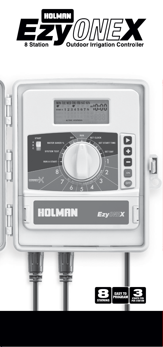
Quick Setup Guide
Our EzyOneX works like a clock, sending an electrical signal to solenoid valves located around your garden. These valves divide the system up into zones or STATIONS. This helps to maintain the right amount of pressure for your sprinklers. Each solenoid is
connected to the EzyOneX via an individual cable. To complete the electrical circuit, a COMMON wire runs from the EzyOneX to all your valves. To open a valve (or water a STATION), the EzyOneX sends an electric current to lift a plunger in the solenoid coil.
After the RUN TIME has expired, the electric current is discontinued and the valve closes. The EzyOneX will then automatically open the next valve in the sequence, continuing this way until all allocated STATIONS have been watered. In addition, the EzyOneX
can have up to three different START and RUN TIMES on each station.
SET CLOCK
i. Turn the MAIN DIAL
to SET CLOCK
ii. Use to scroll between
minutes, hours and days
iii. Use or to adjust time
LHint: You must have the
current day and time set to
begin setting your watering,
ensuring AM/PM is correct
RUN A START SEQUENCE
i. Turn the MAIN DIAL
to RUN A START
ii. Press to run the
desired RUN TIME
LEach STATION 1through 8
will run sequentially as per
the set watering durations
LPress to cancel all
watering immediately
SYSTEM TEST
i. Turn the MAIN DIAL
to SYSTEM TEST
ii. Each station is pre-set for 2
minutes. Press to commence
iii. Press to scroll
through stations
iv. Press to stop it any time
LHint: Use this to automatically
run through all stations
on the controller
LThis is ideal for checking
the operation of your
watering system
LWhile the system test is running,
use or to adjust test duration
MANUAL STATION WATERING
LRUN TIME will be set
to OFF by default
LAdjust the run time
below 1 or above 255 to
turn the station OFF
i. Press to water this station
immediately for the set duration
ii. Press to stop watering
MOUNTING THE UNIT
Position the unit in a place that
is convenient for valve wiring
and near a power source
LInstall near a 240V AC outlet
LWe recommend mounting
the unit at eye level
i. Drive a #8 screw into the
wall, leaving approx. 4mm
exposed. Use a toggle bolt or
masonry plug if necessary
ii. Hang the unit from the
key at the back, ensuring
it is properly seated
iii. Optional: Remove the terminal
cover to add additional screws
through the holes in the lower
corners for extra stability
STOP ALL WATERING
1. Turn the MAIN DIAL to OFF
LThis will hold all set watering
LThis is ideal during wet
weather to suspend all
watering until the dial is
turned back to RUN
SEASONAL WATER SAVING
LWatering durations can be
adjusted proportionally by a
percentage from 10-100%
LE.g. Water 100% during Summer,
and 40% during Autumn
i. Turn the MAIN DIAL to
WATERSAVER%
ii. Use or to adjust the
WATER SAVER % shown on the
display in 10% increments
5
SET WATERING DURATION PER STATION
i. Use the MAIN DIAL to select
a STATION from 1to 8
ii. Adjust the RUN TIME
using or
SET DAY
i. Turn the MAIN DIAL to SET DAY
ii. Use to scroll through
MON to SUN
iii. Use or toggle each day
ON or OFF as indicated by
LHint: All days MON to SUN
will be set to ON by default
4
SET START TIME
i. Turn the MAIN DIAL to
SET START TIME
ii. Use or to adjust time,
ensuring AM/PM is correct
iii. Use to scroll between
minutes and hours
LPress to delete a start time
LHint: Each station will water a
full RUNTIME and then stop,
then the next station will run in
sequence, one after the other
3
2
CHOOSE A START SEQUENCE
i. Set the SLIDER SWITCH
to START A
LHint: START B and Care
only required if multiple
times are needed per
station, on different days
9V
ALKALINE
BATTERY
4 6
MC1 2 3
2
M
4 5 6 7 8
1 3 5 7
8
C
OFF
ON
S
E
T
W
A
T
E
R
I
N
G
D
U
R
A
T
I
O
N
P
E
R
S
T
A
T
I
O
N
2
1
3
4
5
6
7
8
RUN SET CLOCKOFF
WATER SAVER %
SYSTEM TEST
RUN A START
SET START TIME
SET DAY
START
A
B
C
24V AC
SLIDER SWITCH
RUN
LLeave the MAIN DIAL on
RUN to automatically water
as per set schedules