manuals.online logo
Brands
  1. Home
  2. •
  3. Brands
  4. •
  5. HOLOVISION
  6. •
  7. Control Unit
  8. •
  9. HOLOVISION 101 Service manual

HOLOVISION 101 Service manual

This manual suits for next models

5

Other HOLOVISION Control Unit manuals

HOLOVISION VIO2 Service manual

HOLOVISION

HOLOVISION VIO2 Service manual

HOLOVISION VIO Service manual

HOLOVISION

HOLOVISION VIO Service manual

Popular Control Unit manuals by other brands

Seitz 14A80 user manual

Seitz

Seitz 14A80 user manual

Wilo RS485 Installation and operating instructions

Wilo

Wilo RS485 Installation and operating instructions

Becker CentralControl CC41 Commissioning Instruction

Becker

Becker CentralControl CC41 Commissioning Instruction

SICK CDB650 operating instructions

SICK

SICK CDB650 operating instructions

Panduit NetKey NKP5E88M Series installation instructions

Panduit

Panduit NetKey NKP5E88M Series installation instructions

MX Options Concentric Petite Fitting instructions

MX

MX Options Concentric Petite Fitting instructions

Clean Water Systems Fleck 2510 Installation & start?up guide

Clean Water Systems

Clean Water Systems Fleck 2510 Installation & start?up guide

Fairchild FSB44104A user guide

Fairchild

Fairchild FSB44104A user guide

LEGRAND Wattstopper LMIN-104 installation instructions

LEGRAND

LEGRAND Wattstopper LMIN-104 installation instructions

PMK ATT10BNCS instruction manual

PMK

PMK ATT10BNCS instruction manual

Tektronix TDS3FFT user manual

Tektronix

Tektronix TDS3FFT user manual

Woodward easYgen Technical manual

Woodward

Woodward easYgen Technical manual

Balluff BNI EIP-502-105-R015 user guide

Balluff

Balluff BNI EIP-502-105-R015 user guide

NXP Semiconductors TWR-LS1021A Getting started

NXP Semiconductors

NXP Semiconductors TWR-LS1021A Getting started

Advantech PCM-3117 Startup manual

Advantech

Advantech PCM-3117 Startup manual

Danfoss MCO 101 manual

Danfoss

Danfoss MCO 101 manual

Moons' Lin Engineering R701P user manual

Moons'

Moons' Lin Engineering R701P user manual

Aventics RV1 operating instructions

Aventics

Aventics RV1 operating instructions

manuals.online logo
manuals.online logoBrands
  • About & Mission
  • Contact us
  • Privacy Policy
  • Terms and Conditions

Copyright 2025 Manuals.Online. All Rights Reserved.

Manual ype 1.1.0.2-RF
KX- 30865 With 265 Controller
For Models
101
103
201
203
301
302
Specifications
Communication
For use with all Panasonic KSUs with
door phone card.
Installer furnishes his own KX-T30865 door
phone and attaches to Holovision plate with
bracket which is supplied.
Access Control
Essex 265 controller
2 relays
5-6 users
16.5 VAC power supply included
INS ALLA ION
INS RUC IONS
501 E. Goetz Ave.
Santa Ana, Ca 92707
www.eholovision.com
Ph. 714-434-6904
Fax 800-362-0002
HOLOVISION
Front View
To Panasonic
KSU
R
T
KX- 30865
Door bell button
See assembly note on page 7
Essex Keypad Wiring
*MOV (metal oxide varistor) is the small red component which is included. Its purpose is to absorb “inductive kick back” which can be created when power is removed from
the strike.
Page 2 YPE 1.1.0.2-RF
NO E:
Jumper Wire is Required
Essex Model 265
NC 2
NO 2
COM 2
NC 1
NO 1
COM 1
+DC
- OUT
AC
IN
Remote
Monitor
Earth
Holovision Entry
System with
Keypad
Keypad cable (22/12)l
16.5
VAC
The 265 module comes with jumpers and MOVs prewired to the left side of the terminal stirp. Remove all wires from left side of terminal strip and wire per this diagram
Gate
Strike
MOV
is recommended
COineIn
KSU
To Phones
Strike 1
Door 1
Pan
Doorphone
Pan
Doorphone
AC Out For Strike
NO E:
Jumper Wire is Required
Essex Model 265
NC 2
NO 2
COM 2
NC 1
NO 1
COM 1
+DC
- OUT
AC
IN
Remote
Monitor
Earth
Holovision Entry
System with
Keypad
Keypad cable (22/12)l
16.5
VAC
Gate
Strike
MOV
is recommended
COineIn
KSU
To Phones
Strike 1
Door 1
DC Out For Strike
YPE 1.1.0.2-RF Page 3
Essex Keypad Wiring
Contact Closure for Gate Operation
Essex Model 265
NO E:
Jumper Wire is Required
Panasonic Compatable
Door Station
Holovision Entry
System with
Keypad
Cat 5
Pink
To Doorphone Port on
KSU Door Card
Relay Out
KSU Door
Card
16.5 VAC
40 VA
NC 2
NO 2
COM 2
NC 1
NO 1
COM 1
DC
OUT
AC
IN
Remote
Monitor
Earth
Keypad Cable 22/12
KSU “Open”
Terminals
on Gate
Motor
NOTE : Remove the jumper wire & MOVs from left side terminal strip. Wire right side terminal
strip “color for color”.
Page 4 YPE 1.1.0.2-RF
Set Essex Relay Options
Step Action
GOAL: To use jumper pins on circuit board to configure standard relay options.
In this configuation, Codes 1 and 2 operate Relay 1.
Codes 3, 4, 5 operate Relay 2.
1 Relay 1 and 2 activate. Only Relay 1 latch*
Code Relay 1 Relay 2
Open atch Open atch
Master Code No No No No
Code 1,2 Yes Yes No No
Code 3, 4, 5 No No Yes No
o
o
o
o
o
o
o
o
o
o
o
o
o
o
o
o
o
o
o
o
o
Master Unlock
1, 2 Unlock
3,4,5 Unlock
1,2 atch
3, 4,5 atch
CCTV
Doorbell
Relay 1
Relay 2
Step Action
2 Relay 1 and 2 activate and latch*
Code Relay 1 Relay 2
Open atch Open atch
Master Code No No No No
Code 1,2 Yes Yes No No
Code 3, 4, 5 No No Yes Yes
o
o
o
o
o
o
o
o
o
o
o
o
o
o
o
o
o
o
o
o
o
Master Unlock
1, 2 Unlock
3,4,5 Unlock
1,2 atch
3, 4,5 atch
CCTV
Doorbell
Relay 1
Relay 2
*LA CHING RELAY: In order to latch either relay, simply enter the code, followed by “7”.
Repeat (code, 7) in order to unlatch the relay.
The top example would be used where the driveway gate was connected to Relay 1 (and
could be locked open), and the pedestrian gate was connected to Relay 2. (No latching
possible).
1 Press “Program” switch once. (keypad will beep 4 times)
2 Once “Program” switch is pressed, you have 2 minutes to complete Step 5
.
3 Press “1119”. (you will hear 3 beeps)
4 Step 5 must be completed within 5 seconds of Step 3.
5 Enter “Master Code” *
6 Wait 5 seconds for 3 beeps to confirm new “Master Code”.
Set Master Code
Step Action
1 Enter “Master Code”
2 Enter 113 (3 beeps).
3 Enter User Code 2.
4 Wait 5 seconds for 3 reset beeps.
Set User Code 2
Step Action
1 Enter “Master Code”
2 Enter 115 (3 beeps)
.
3 Enter User Code 3.
4 Wait 5 seconds for 3 reset beeps.
Set User Code 3
Step Action
1 Enter “Master Code”
2 Enter 111 (3 beeps).
3 Enter User Code 1.
4 Wait 5 seconds for 3 reset beeps.
Set User Code 1
Step Action
YPE 1.1.0.2-RF Page 5
Programming of Essex Keypad
1 Enter “Master Code”
2 Enter 117 (3 beeps).
3 Enter User Code 4.
4 Wait 5 seconds for 3 reset beeps.
Set User Code 4
Step Action
GOAL: Set-up master and user codes
* MAS ER CODE: The default Master Code is 13579. This should be replaced by a unique code to be used only by
your company. The Master Code can be 3 to 8 digits long.
Page 6 YPE 1.1.0.2-RF
Programming of Essex Keypad
1 Enter “Master Code”
.
2 Enter 119 (3 beeps)
.
3 Enter User Code 5.
4 Wait 5 seconds for 3 reset beeps.
Set User Code 5
Step Action
1 Enter Master Code .
2 Enter address of code to be deleted (111, 113, etc.).
3 Do not enter any code until you hear 3 reset beeps.
4 Wait 5 seconds for 3 reset beeps.
Delete Any Code
Step Action
Note: User codes can be 3 to 8 digits
1 Enter any User Code (1 -5).
2 Enter “7”. This will cause the relay to latch (subject to the jumper pin settings - see Page 5)
.
3 To unlatch the relay, re-enter the user Code, followed by “7”.
Step Action
atch a Relay
YPE 1.1.0.2-RF Page 7
Programming of Essex Keypad
Assembly of KX- 30865
Note: The above 2 steps are actually setting the activation times for user code 1, 2 and user code
3, 4, 5. Using the jumper pin setting as shown in “Set Essex Relay Options”, this will set activaiton time of Relays 1 & 2.
1 Press “Program” switch (keypad will beep 4 times)
2 Enter 1117 (3 beeps)
3 Enter 1 for every 1 second latch time, and 5 for every 5 seconds.
Examples
6 seconds = 5, 1
8 seconds = 5, 1, 1, 1
12 seconds = 5, 5, 1, 1
4 Wait 5 seconds for 4 reset beeps.
Set Activation Time Of Relay 1 (User codes 1 & 2 - see note below)
Step Action
1 Press “Program” switch (keypad will beep 4 times)
2 Enter 1115 (3 beeps)
.
3 Enter 1 for every 1 second latch time, and 5 for every 5 seconds.
Examples:
6 seconds = 5, 1
8 seconds = 5, 1, 1, 1
12 seconds = 5, 5, 1, 1
4 Wait 5 seconds for 4 reset beeps.
Set Activation Time Of Relay 2 (User codes 3, 4& 5 - see note below)
Step Action
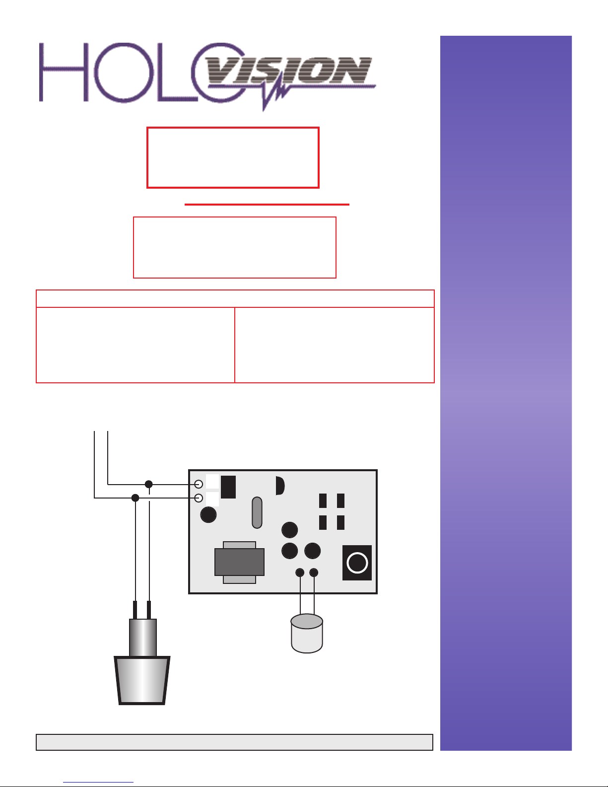
1 Disassemble KX-T30865
2 Cut input wires free from plastic back plate
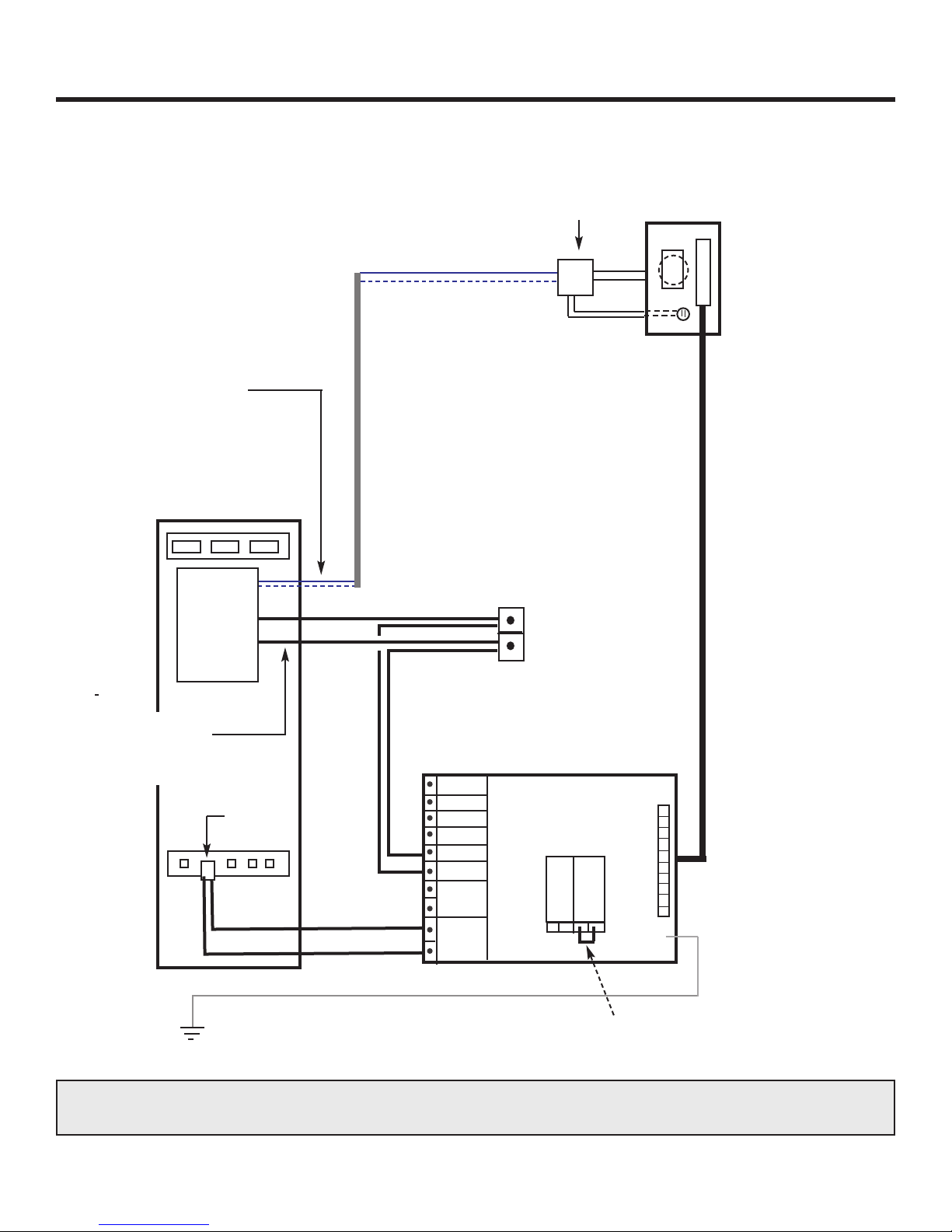
3 Connect doorbell button, circuit board, and wires to KSU as shown on page 1
4 Attach circuit board to metal bracket using small screw
5 Secure the speaker and microphone to the back of the plate using the bracket
6 Connect to Panasonic KSU
STEP ACTION
501 E. Goetz Ave.
Santa Ana, Ca 92707
Ph. 714-434-6904
Fax 800-362-0002
www.eholovision.com