Rev. 1.00 6 December 13, 2018 Rev. 1.00 7 December 13, 2018
Gang-Writer8-8 User’s Guide Gang-Writer8-8 User’s Guide
Programming Mode Selection
Either 2 or 4 site parallel programming can be selected using the OPTION S/W settings according
to the actual requirements, as shown in Figure 8 and Table 1. With regard to 6 or 8 site parallel
programming description, refer to 3.2 Programming Mode Selection.
Figure 8. OPTION S/W
Switch1 Switch2 Site Settings
OFF OFF Enable the ICP1~ICP4 programming – factory default
ON OFF Enable the ICP1 and ICP2 programming
OFF ON Enable the ICP3 and ICP4 programming
ON ON Enable the ICP1 and ICP3 programming
Table 1. OPTION S/W Site Settings
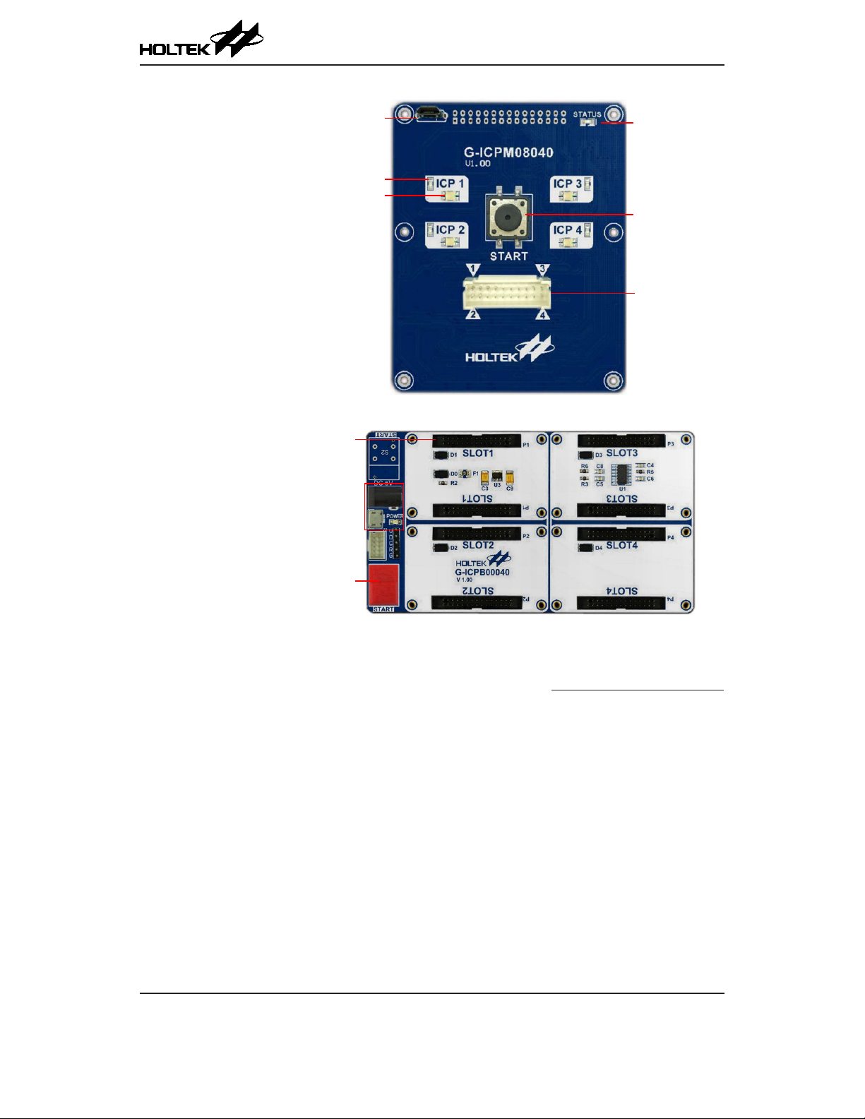
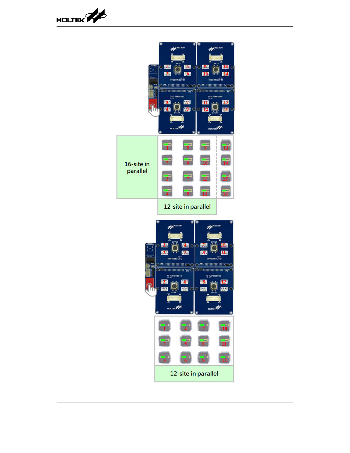
3 Using the Programming Module together with the Base Board
In the offline programming mode, using the programming module together with the base board
can implement 2/4/6/8 sites parallel programming in the standard mode or 12/16 site parallel
programming in the extension mode. To implement programming module oine data download,
connect the programming module to the PC via a USB cable directly. It is not necessary to remove it
from the base board.
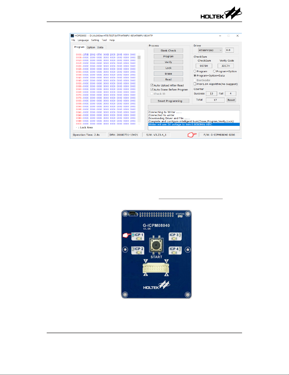
3.1 Oine Programming Mode
Oine Programming Data Download
The hardware connection is shown in Figure 9 and the specific operation steps are the same as
2.2 Oine Programming Mode – Oine Programming Data Download.