Holzstar SAA Series User manual

SAA 2001
Operating Instructions
SAA SERIES
Chip Extraction Unit
SAA 2001
SAA 2003
SAA 3001
SAA 3003
SAA 3001

2 SAA Series | Version 1.06
Imprint
Product identification
Chip Extraction Unit Art. No.
SAA 2001 5922201
SAA 2003 5922203
SAA 3001 5922301
SAA 3003 5922303
Manufacturer
Stuermer aschinen GmbH
Dr.-Robert-Pfleger-Str. 26
D-96103 Hallstadt
Germany
Fax: 0049 (0) 951 96555 - 55
Internet: www.holzstar.de
Information about the operating instructions
Original operating instructions
Published: 07.02.2019
Version: 1.06
Language: English
Author: ES
Copyright information
Copyright © 2019 Stürmer aschinen GmbH, Hallstadt,
Germany.
Stürmer aschinen GmbH is the sole owner of the con-
tent of these operating instructions.
Forwarding and reproduction of this document as well as
use and notification of its content is not permitted without
explicit consent. Infringements will lead to claims for da-
mages.
Subject to technical changes and errors.
Contents
Imprint..................................................... 2
Contents ................................................. 2
1 Introduction ............................................ 3
1.1 Copyright ........................................................... 3
1.2 Customer service...............................................3
1.3 Disclaimer..........................................................3
2 Safety ...................................................... 3
2.1 Legend of symbols............................................. 3
2.2 Operator responsibility....................................... 4
2.3 Operating staff qualification ............................... 4
2.4 Personal protective equipment .......................... 5
2.5 Safety labels on the Chip Extraction Unit .......... 5
2.6 General safety aspects...................................... 6
2.7 Safety aspects in dealing with electricity ........... 6
2.8
Safety aspects in dealing with application of tools
.. 7
2.9 Safety to operation............................................. 7
2.10 S
afety aspects on servicing and maintenance
..... 7
2.11 Security check ................................................. 7
3 Intended use ........................................... 8
4 echnical Data........................................ 8
4.1 Table ................................................................. 8
4.2 Type plate..........................................................8
5 ransport, packaging, storage.............. 8
5.1 Delivery and transport........................................ 8
5.2 Packaging..........................................................8
5.3 Storage .............................................................. 8
6 Machine description .............................. 9
6.1 Illustration ..........................................................9
6.2 Scope of supply ................................................. 9
6.3 Optional accessories ........................................ 9
7 Installation and connection................... 9
7.1 Requirements to the installation location ........... 9
7.2 Set up the Chip Extraction Unit.......................... 10
7.3 Initial operation the Chip Extraction Unit............ 10
7.4 Electrical connection.......................................... 10
8
Installation of the Chip Extraction Unit
.....11
9 Maintenance and Service........................12
10 Malfunctions, their potential causes
and remedies..........................................13
11 Disposal, reusing used machines........13
11.1 Decommissioning ............................................ 13
11.2 Disposal of electrical equipment...................... 13
11.3 Disposing of lubricants..................................... 13
11.4 Disposal by municipal collection point ............. 14
12 Spare parts.............................................14
12.1 Spare parts orders........................................... 14
12.2 Spare parts drawings....................................... 15
12.3 Spare parts list SAA 2001/ SAA 2003 ............ 17
12.4 Spare parts list SAA 3001/ SAA 3003 ............. 17
13 Wiring diagrams....................................18
14 EC - Declaration of Conformity.............19

Introduction
SAA Series | Version 1.06 3
1 Introduction
You have made an excellent choice in purchasing a
HOLZSTAR Chip Extraction Unit.
Carefully read the operating instructions prior to
commission-ing.
They describe correct commissioning, intended use and
safe as well as efficient operation and maintenance of
the Chip Extraction Unit.
The operating instructions form part of the Chip Extrac-
tion Unit. Always keep them at the Chip Extraction Unit´s
location of use. Please also observe the local accident
prevention regulations and general safety regulations for
the use of the Chip Extraction Unit.
1.1 Copyright
The contents of these operating instructions are pro-
tected by copyright. Their use is permitted within the con-
text of using the Chip Extraction Unit. Any further use
shall not be permitted without written consent by the ma-
nufacturer.
To protect our products, we register our rights to our
brands, patents and designs where possible in each indi-
vidual case. We take strong action against any violation
of our intellectual property.
1.2 Customer service
Please contact your specialist retailer if you have any
questions regarding your Extraction Unit or require any
technical information. Your specialist retailer will be
happy to support you with specialist advice and informa-
tion.
Germany:
Stürmer aschinen GmbH
Dr.-Robert-Pfleger-Str. 26
D-96103 Hallstadt / Germany
Repair service:
Fax: 0951 96555-111
E-Mail: service@stuermer-maschinen.de
Internet: www.holzstar.de
Spare parts orders:
Fax: 0951 96555-119
E-Mail: ersatzt[email protected]
Please submit any information and experiences you
make during application of the machine as these may be
valuable for product improvements.
1.3 Disclaimer
All data in this operation manual has been compiled on
the basis of the state-of-the-art, valid standards and gui-
delines as well as our many years of expertise and expe-
rience.
The manufacturer shall not be liable for damage in the
following cases:
- Failure to comply with the operation manual,
- Unintended use
- Deployment of untrained staff
- Conversions at one's own responsibility
- Technical modifications
- Use of unauthorised spare parts
The actual scope of delivery may deviate from the des-
criptions and illustrations in this document as a result of
special variants, optional extras or recent, technical mo-
difications. The obligations defined in the supply contract
shall apply in addition to the general terms and conditi-
ons and the manufacturer's general terms and conditions
as well as the statutory regulations valid at the time of
the conclusion of the contract.
2 Safety
This section provides an overview of all important safety
packages for personal protection as well as safe and re-
liable operation. The individual sections contain additio-
nal, task-specific safety information.
2.1 Legend of symbols
Safety instructions
Safety instructions in this operation manual have been
highlighted with symbols. Safety instructions are indica-
ted by signal terms that express the degree of risk
involved.
WARNING!
This combination of symbol and signal term indica-
tes a directly dangerous situation which may cause
death or serious injury if not averted.
A EN ION!
This combination of symbol and signal term indica-
tes a potentially hazardous situation which may
cause minor or light injuries if it is not averted.

4 SAA Series | Version 1.06
Safety
ips and recommendations
Observe the safety information in these operating in-
structions to minimise the risk of personal injury as well
as material damage and prevent hazardous situations.
2.2 Operator responsibility
Operators are defined as the persons who operate the
machine for commercial or profitbased purposes or pro-
vide the machine to third parties for use or application
and bear the legal product responsibility in terms of the
protection of users, staff or third parties during operation.
Obligations of the operator:
If the machine is used for commercial purposes, opera-
tors are subject to the legal stipulations in terms of occu-
pational safety. For this reason, the safety instructions in
these operating instructions as well as the safety, acci-
dent prevention and environmental protection regulati-
ons valid at the installation location must be complied
with. In this process, the following shall apply in
particular:
- Operators shall obtain information about valid oc-
cupational safety regulations and determine addi-
tional hazards as part of a risk assessment which
result from the specific operating conditions at the
machine's installation location. Said risk as-
sessment shall be reflected in operating instructi-
ons for machine operation.
- During the entire machine operating time operators
must check whether the operating instructions they
created meet current standards and adapt the ope-
rating instructions where necessary.
- Operators shall clearly manage and specify the re-
sponsibilities for installation, operation, trouble-
shooting, maintenance and cleaning.
- Operators must make sure that all persons hand-
ling the machine have read and understood these
operating instructions. Operators must also regu-
larly train staff and notify of the hazards.
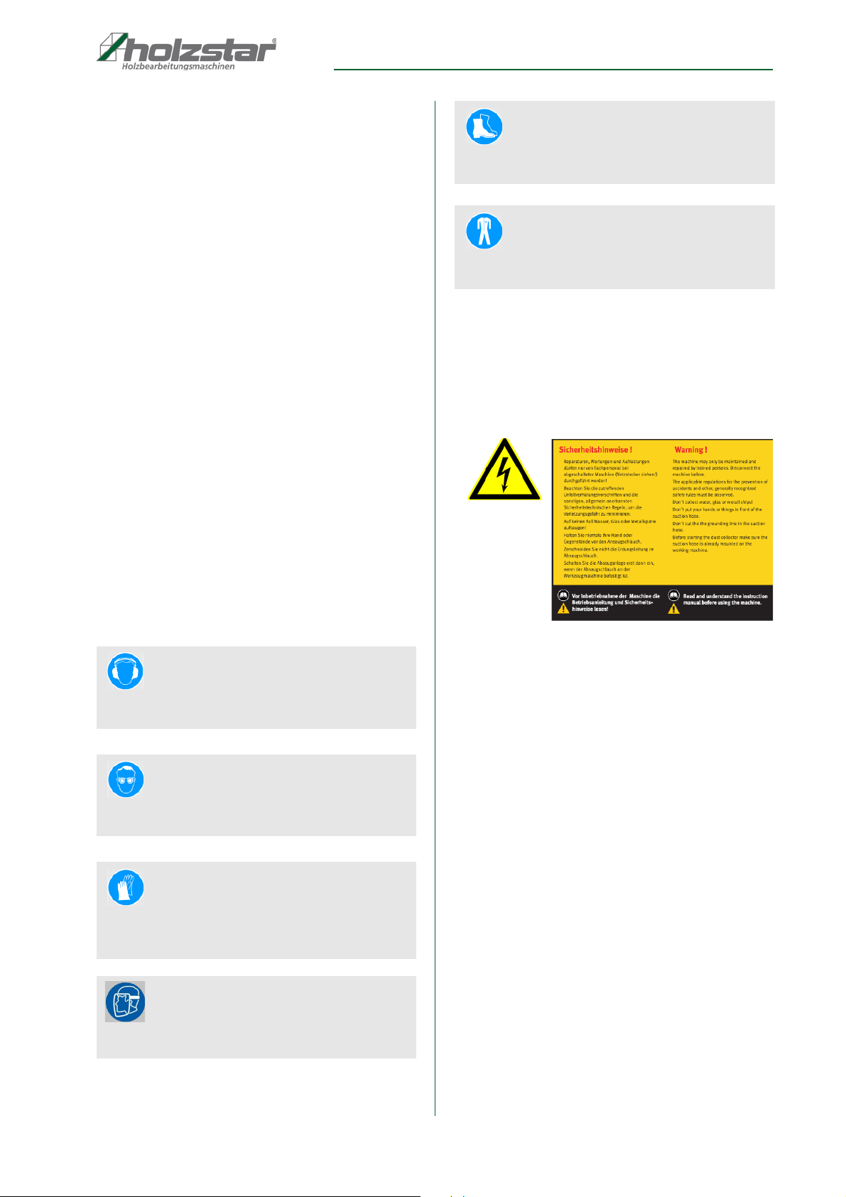
- Operators shall provide staff with the required pro-
tective equipment and wearing the required protec-
tive equipment shall be mandatory.
Operators shall also be responsible for maintaining the
machine in a technically perfect condition. For this rea-
son, the following shall apply:
- Operators shall make sure that the maintenance in-
tervals described in these operating instructions
are complied with.
- Operators shall regularly check that the safety
equipment is fully functional and complete.
2.3 Operating staff qualification
The different tasks described in these operating instructi-
ons require different levels of skills in terms of the qualifi-
cations of operating staff working with the machine.
Exclusively persons of whom it can be expected that
they reliably complete assigned tasks shall be authori-
sed to carry out any tasks. Persons whose reactions
have been impaired shall not be authorized, e.g. drug
users, users under the influence of alcohol or medica-
tion.
These operating instructions specify the following perso-
nal qualifications for the different tasks:
Operating staff:
Operating staff has undergone an induction by the ope-
rator about the entrusted tasks and potential hazards re-
sulting from improper behaviour. Tasks which go beyond
normal operation may only be carried out by the operator
if they are listed in the operation manual and the opera-
tor has made him/herself familiar with them.
IMPOR AN !
This combination of symbol and signal term indica-
tes a potentially dangerous situation which may
cause material damage or harm the environment if it
is not averted.
NO E!
This combination of symbol and signal term indic tes
a potentially dangerous situation which may cause
material damage or harm the environment if it is not
averted.
ips and recommendations
This symbol highlights useful tips and recommendati-
ons as well as information for efficient and reliable
operation.
WARNING!
Risk from inadequately qualified
persons!
Inadequately qualified persons are unable to assess
the risks when handling the machine, thus putting
themselves and others at risk of severe injuries.
- All work must be carried out by qualified persons
only.
- Keep inadequately qualified persons and children
away from the work area.

Safety
SAA Series | Version 1.06 5
Qualified electrician:
Due to the electrician's specialised training, know-how,
experience and knowledge of pertinent standards and
regulations the electrician is in a position to work on the
electrical systems, and autonomously identify and avoid
potential hazards.
Specialist staff:
As a result of specialist training, expertise, experience
and skills in terms of the relevant standards and regulati-
ons, specialist staff is able to complete the tasks they are
entrusted with and independently identify hazards and
avert risks.
Manufacturer:
Certain work must be carried out by manufacturer spe-
cialist staff only. Other staff is not permitted to carry out
this work. Contact our customer service to have the work
carried out.
2.4 Personal protective equipment
Personal protective equipment is intended to protect the
health and safety of persons at work. Staff must wear the
personal protective equipment indicated in individual
sections of these operating instructions when carrying
out the different tasks on the machine.
The personal protective equipment is described in the
following section:
2.5 Safety labels on the Chip Extraction Unit
The following safety labels and instructions are attached
to the Chip Extraction Unit s (Fig. 1) and must be
observed.
Fig. 1: Safety labels:1 Warning of dangerous electrical voltage |
2 Safety instructions
If safety labels on the machine are damaged or missing,
this can cause errors, personal injury and material da-
mage. The safety symbols attached to the machine must
not be removed. Damaged safety symbols must be re-
placed immediately.
As soon as the signs are not clearly visible and compre-
hensible at first glance, the machine must be stopped
until new signs have been attached.
Hearing protection
Hearing protection protects the ears against hearing
damage caused by noise.
Eye protection
Protective glasses protect the eyes against projected
parts and splashes of liquid.
Protective gloves
Protective gloves protect the hands from compo-
nents with sharp objects as well as friction, abrasion,
and deep-cut injuries.
Protection of face
The face protection prevent the face of objects flying
around.
Safety shoes
Safety shoes protect feet from pinching, falling parts
and slipping on slippery surfaces.
Protective clothing
Protective work clothing means tight-fitting clothing
with low tear resistance.
2
1

6 SAA Series | Version 1.06
Safety
2.6 General safety aspects
Note the following:
1. The Extraction Unit may be served only by persons
who have read and understood this manual. The ope-
rator must be trained in use, setting and service.
2. If you transmit this Extraction Unit, you must hand
over all tools provided to the withdrawal system and
documents.
3. Switch on the machine only immediately before the
beginning of the exhaust process. Switch off the ma-
chine during breaks and when the machine is not in
operation. Don´t leave the machine unattended, if it is
ready for use.
4. Never open the protective covers by hand, while the
Chip Extraction Unit is in operation.
5. Keep the working area and the floor nearby the Chip
Extraction Unit free of any objects which endanger
your stability or show a trip danger. Keep the working
area clean. ess can cause accidents.
6. Control the safety area of the machine before and du-
ring operation that unauthorized people keep off.
Don´ t let the Chip Extraction Unit touch by other
people, in particular by children.
7. Don´ t use the machine close to ignitable gases, li-
quids and solids. Flying sparks can cause danger of
explosion or fire risk.
8. Use the machine only in dry rooms or in dry surroun-
dings and provide for sufficient illumination.
9. Protect the working area against rains, moisture and
humidity, to avoid electrical danger.
10. Never leave a running machine unattended. Switch
off the machine before leaving the workplace.
11. Wood dust is explosive and can be harmful to health.
In particular, tropical woods and hardwoods such as
beech and oak are classified as carcinogenic.
12. Work with reason and with concentration. Do not use
the Extraction Unit if you are not concentrated.
13. The operation or servicing of the Chip Extraction Unit
is forbidden for people who are less than 18 years or
are under influence of alcohol or drugs.
14. Check the material to be worked on before starting
the Extraction Unit and check about a possible health
danger by released dust. Take suitable precautions if
necessary.
15. While working with the Chip Extraction Unit a hearing
protection is always to be carried. Carrying of loose
clothes (ties, scarfs, open jackets and not clinging clo-
thes) is forbidden. There is injury danger by getting
stuck or by insertion in moving machine parts. A hair-
net is to be carried on long hair.
16. Protect yourselves from noise by carrying a suitable
and admitted hearing protection.
17. Avoid an unnatural position and keep the balance at
any time. Wear protective shoes to raise stability.
Carry safety clothes.
2.7 Safety aspects in dealing with electricity
Please observe the following:
1. To protect against an electric shock the machine must
be connected only by an electric expert.
2. Do not use the aspiration system if it cannot be swit-
ched on or switched off properly and if the control
components do not reach proper operation
conditions.
3. Protect the mains connection cable against heat, oil
and sharp edges.
4. Exchange a damaged mains connection cable imme-
diately.
A EN ION!
In spite of taking care of all working tips, security and
accident prevention regulations a rest risk continues
with the contact with the machine.
By concentrated and farsighted work and action you
can diminish the rest risk.
A EN ION!
The conditions on electric devices are valid for the
Chip Extraction Unit. These are to be checked by an
approved electric expert in a regular time interval
according to their electrical security. The test cycles
are depending on the regulations to consider.

Safety
SAA Series | Version 1.06 7
2.8 Safety aspects in dealing with application
of tools
Please observe the following:
1. Use only dust bags which are not damaged.
2. Use only original metal strength-dust bags.
3. Exchange damaged dust bags immediately. Until re-
placement of the dust bag the use of the machine is
prohibited.
4. Always use new dust bags
2.9 Safety to operation
Please observe the following:
1. Do not overload the Chip Extraction Unit. It works bet-
ter and safer in the specified performance range.
Don´t use the Extraction Unit for operation a stronger
machine is required for.
2. Check the stability of the machine.
3. Please note, that the use of different tools not recom-
mended by the manufacturer may cause danger of in-
jury for the operator.
4. Do not allow any tools to be inserted. Check that all
tools are removed before starting the machine.
5. This machine is not suitable for aspiration of dange-
rous dust.
6. If necessary, wear suitable personal protective equip-
ment. This could be: Hearing protection to avoid the
risk to damage hearing; breathing protection to avoid
the risk of breathing dangerous dust.
7. Take care that the aspiration system cannot be started
during servicing work and changement of dust bag.
8. Never touch the machine during operation.
9. Provide for good illumination.
10. To avoid contact with the blower wheel, unused
exhaust connections must always be covered.
11. While working outside good footwear is recommen-
ded.
12. Keep the working area free of rubbish.
13. All protective devices must be mounted immediately
after servicing.
2.10 Safety aspects on servicing and main-
tenance
1. After servicing, repair and cleaning please check
whether all protective devices are mounted properly
again, and no more tools are left inside the machine.
2. Damaged safety devices, machine parts and counters
must be exchanged in accordance with the require-
ments by an approved professional workshop.
3. Repairing work at electric power tools must be carried
out only by an electric expert. Only original spare parts
may be used. Otherwise there is danger of accident
for the operator.
2.11 Security check
Check the Chip Extraction Unit regularly.
Check all security devices
- before start working,
- once weekly (at continuous operation),
- after every servicing and repair.
A EN ION!
- Use the machine only for designated operational.
- Don't use the machine for operation which it is not
made for.
Breathing protection
A dust protection mask (filter mask with particle filter)
is to be worn during the changement and emptying of
the dust bag.
WARNING!
At servicing and repair work always switch off the
machine at the main switch and protect it against a
start.

8 SAA Series | Version 1.06
Intended use
3 Intended use
The Chip Extraction Unit serves for the extraction of
chips and dust which are produced when wood or wood-
like materials are processed. The Extraction Unit is con-
structed for the application in not explosion-threatened
surroundings and may be installed and operated in dry
rooms only. The observance of all information in these
instructions also belongs to the designated use. Every
different use except of the designated use is considered
as a false use.
The exhaust system has not been designed for commer-
cial, craft or industrial use. We do not assume any war-
ranty if the machine is used in commercial, handicraft or
industrial drives as well as in similar activities.
Claims of any kind for damages caused by improper use
are null and void.
4 Technical Data
4.1 Table
4.2 Type plate
Fig. 2: Type plate SAA 2003
5 Transport, packaging, storage
5.1 Delivery and transport
Check the Chip Extraction Unit for visible transport da-
mage upon delivery. In case of visible damage to the
Chip Extraction Unit, immediately notify the carrier or
your retailer.
5.2 Packaging
All of the Chip Extraction Unit‘s packaging materials and
packing aids are suitable for recycling and must always
be disposed of using material-based recycling systems.
Packaging materials made of cardboard must be shred-
ded and recycled as waste paper.
The foils are made of polyethylene (PE), padding is
made of polystyrene (PS). Dispose of these substances
at a recycling centre or hand them over to a qualified wa-
ste disposal company.
5.3 Storage
Always store the Chip Extraction Unit in a clean condition
and a dry, clean and frost-free environment. It must not
be stored in the same room as chemicals.
Cover the machine with a protective tarpaulin.
WARNING!
On not designated use of the aspiration system there
will be generated dangers for the staff, the aspiration
system and other objects of the operator, furthermore
the function of the machine can be affected.
Model SAA 2001/
SAA 2003
SAA 3001 /
SAA 3003
Air flow rate 2.553 m³/h 3.910 m³/h
Duct input Ø 125 mm Ø 150 mm
Duct output 2 x Ø100 mm 3 x Ø100 mm
otor output 1,5 kW 2,2 kW
Dimensions
[L x W x H]
1.000 x 750 x
2.000 mm
1.450 x 800 x
2.000 mm
Weight 37 kg 48kg
Electrical connection:
SAA 2001/ SAA 3001 230 V/50 Hz
SAA 2003 / SAA 3003 400 V/50 Hz

Machine description
SAA Series | Version 1.06 9
6 Machine description
6.1 Illustration
Figures in this operation manual serve to provide a
basic understanding and may differ from the actual
design.
Fig. 3: Chip Extraction Unit SAA 3001
6.2 Scope of supply
1. Filter bag
2. Chip bag
3. Operating instructions
6.3 Optional accessories
7 Installation and connection
7.1 Requirements to the installation location
Remove the chip extraction unit from its packaging and
remove all protective foils.
To achieve a good function and a long life of the Chip
Extraction Unit, the installation location should satisfy
the following criteria:
- The machine state and machine table must be
stable, level and free of vibrations ground.
- Don´t expose the machine to moisture, rain or
snow. Don‘t place or operate the machine in a hu-
mid or wet environment.
- The installation or worker area must be dry and
well ventilated.
- The ambient temperature must be within -10 °
to + 50 ° Celsius, max. air humidity 90%.
- It must be sufficient space for the operator, for ma-
terial transport and for adjustment and main-
tenance work.
- The Chip Extraction Unit must be well grounded.
ains voltage and frequency correspond to the
values of the engine of the machine.
- The installation location must have good illumina-
tion.
Pos. Description Pos. Description
A Connector H Bag
B Fan/ otor
assembly
I Packing
C Casing J Four casters
D Base Plate K Nuts, screws,
washers,
spring washers
E Upper bag support L otor base
F Support rods O Bag clamp
G Intake duct P Filter
R Filter (Inlet)
C
D
B
G
H
J
P
A
F
I
R
O
ips and recommendations
We recommend using only high-quality original Holz-
star accessories. Only with original accessories can
be guaranteed a perfect operation and optimal work
results.
Bezeichnung
PU extraction hose, Ø100 mm/2,5 m
Polyurethane flexible hose, available in 2,5 / 5 / 7,5 or 10
m Lengths, Ø 40 mm, Ø 60 mm, Ø 80 mm, Ø 100 mm, Ø
120 mm
Reducing socket, machine connecting pieces, straight,
non-crimped, interior Ø - 100-60 mm
Floor cleaning set, incl. 2,5 m spiral hose, extraction
pipe, floor nozzle with rollers, handle and 2 pipe clamps
Filterbag for SAA 2001, SAA 2003, SAA 3001 or
SAA 3003
Automatic starting system ALA 2 or ALA10 for SAA 2001,
SAA 2003, SAA 3001, SAA 3003

10 SAA Series | Version 1.06
Installation and connection
7.2 Set up the Chip Extraction Unit
Place the machine on a stable, level ground. The
distance to the wall should be min. 800 mm.
Check the data of electric connection.
The ambient temperature must be within -10 ° to + 50 °
Celsius, max. air humidity 90%.
Don´t expose the machine to moisture, rain or snow.
Carry out maintenance and servicing regularly.
7.3 Initial operation the Chip Extraction Unit
Step 1: Check whether of the extraction hose on to Ex-
traction Unit and the extraction adapter on the
woodworking machine are connected.
Step 2: Check whether the chip bag is good fixed.
Step 3: Switch on first the Chip Extraction Unit and then
only the woodworking machine.
Step 4: Before switch off the extraction unit, first switch
off the woodworking machine.
Step 5: Inspect regularly the chip bag and empty it
if full is.
Step 6: Before operating the on / off switch, make sure
that the filter bag is good fixed.
7.4 Electrical connection
In the follow Steps the Chip Extraction Unit can con-
nected to the electricity network:
Step 1: The Chip Extraction Unit must be off.
Step 2: The Chip Extraction Unit (SAA 2003 und SAA
3003 odel) connect on the 400 V / 3-phase
connection.
Step 3: Check, whether all protective devices are
mounted.
Step 4: Switch on the
Chip Extraction Unit
.
Step 5: Check, whether the direction of rotation of the motor
is correct.
A EN ION!
Risk of injury through a non-stable adjusted machine!
Check the stability of the machine always after instal-
lation or maintenance.
Wear the safety gloves!
Wear the protective clothing!
Wear the safety shoes!
A EN ION!
Observed on the good grounding of
the Extraction Unit!
Static electricity charge leads to
- Deposition of abrasive dust
- Rapid corrosion of the moving parts.
- Spark formation by discharge with explosion
hazard!
A EN ION!
Danger to life due to electrical
shock! !
Danger of live through electric shock by contact with
live power components!
- The Chip Extraction Unit may connected only from
Qualified electrician.
- Work on the electrical system must execute only
from Qualified electrician.

Installation of the Chip Extraction Unit
SAA Series | Version 1.06 11
8 Installation of the Chip Extraction
Unit
Installation of the casters
Fig. 4: Installation of the casters
To assemble, first place the base plate upside down and
attach the four casters to the holes provided and tighten
with wrench (Fig. 4).
Installation of the fan/motor assembly
Fig. 5: Installation of the fan/motor assembly (1)
Step 1: With the motor base, collector body & fan/motor
assembly in place, secure it to the base plate
using the screw and washers provided as shown
in Fig 5.
Fig. 6: Installation of the fan/motor assembly (2)
Step 2: Install the packing and square connecting tube,
connector to the collector body assembly using
screw and washers provided (Fig 6 & Fig 7).
Fig. 7: Installation of the fan/motor assembly (3)
Step 3: Install the two collectors and two packing to the
outlet (Fig 8).
Fig. 8: Installation of the fan/motor assembly (4)
Installation of the support rods
Fig. 9: Installation of the support rods (1)
Step 1: Install the two collector supports and two upper
bag support (Fig 9).
Fig. 10: Installation of the support rods (2)
Step 2: Next, hang the two bags from the support rods.
Then attach the two filterbags and two collection
bags to the collectors using bag clamp.
Step 3: The inlet can now be placed on the intake hole of
the fan/motor assembly (Fig. 10).
Wear protective goggles!
Wear the protective clothing!
Wear the safety shoes!

12 SAA Series | Version 1.06
Maintenance and Service
9 Maintenance and Service Daily Service
- Clean the machine after every use.
- Replace damaged security devices immediately.
Weekly Service
- Clean the machine regularly with a humid cloth and
some soft soap. Don´t use cleaning agents or sol-
vents; these could damage the plastic parts of the
machine. Take care that no water can get into the
machine.
- Keep safety devices, air openings and engine cabi-
net free of dust and dirt. Clean the machine with a
clean cloth or blow it out with air pressure at a low
pressure.
- A dust protection mask is to be worn while chan-
ging and emptying the dust bag.
Monthly Service
- Control fixing bolts of the machine.
Service after 6 month
- Check electric security and safety devices
ips and recommendations
The Chip Extraction Unit is constructed for efficient
operating. To guarantee a long life the servicing
aspects are to be carried out regularly.
A EN ION!
Danger to life due to electrical
shock! !
Danger of live through electric shock by contact with
live power components!
- The Chip Extraction Unit may connected only from
Qualified electrician.
- Repairs on the electrical system must execute only
from Qualified electrician.
- Switch off the machine and pull the plug out before
starting any cleaning or maintenance work.
WARNING!
Risk from inadequately qualified
persons!
Inadequately qualified persons are unable to assess
the risks when handling the machine, thus putting
themselves and others at risk of severe injuries.
All work must be carried out by qualified persons
only.
NO E!
After servicing, repair or cleaning please check
whether all protective devices are mounted properly
again, and no more tools are left inside the machine.
Damaged safety devices, machine parts and coun-
ters must be exchanged in accordance with the requi-
rements by an approved professional workshop.
Wear the safety gloves!

Malfunctions, their potential causes and remedies
SAA Series | Version 1.06 13
10 Malfunctions, their potential causes
and remedies
11 Disposal, reusing used machines
To protect the environment make sure that all machine
components are exclusively disposed of as intended and
legally permitted.
11.1 Decommissioning
Disused machines must be decommissioned immedi-
ately to prevent unintended use at a later point and put-
ting the environment or persons at risk.
Step 1: Disposable environmental in hazardous opera-
ting materials from the end of life device.
Step 2: If necessary, disassemble the machine into as-
semblies and components that are easy to
handle and suitable for recycling.
Step 3: Dispose of the machine components and proces-
sing materials using the intended disposal me-
thods.
11.2 Disposal of electrical equipment
Electrical devices contain a variety of recycling-capable
materials and also environmentally hazardous compo-
nents.
Separate these components and dispose of them appro-
priately. In case of doubt, contact your local waste dispo-
sal authority. Consult a specialist disposal agent for recy-
cling if needed.
11.3 Disposing of lubricants
Lubricant manufacturers provide disposal information for
the lubricants used. If necessary, request productspeci-
fic data sheets.
IMPOR AN !
If one of the following malfunctions occurs, immedi-
ately stop working with the machine. Before you start
troubleshooting, turn off the machine and unplug the
power plug. Failure to do so can lead to serious
injury. All repairs or replacement work may be perfor-
med by qualified and trained expert staff only.
Malfunc-
tion
Possible cause Remedy
achine
does not
start
1. Power plug is
not plugged in.
2. Power supply
cables defec-
tive.
3. Switch defec-
tive
4. otor defective
1. Plug in the po-
wer plug.
2./3./4.
Call a service
technician
Strong
vibrations
1. Loose compo-
nent
2. otor support is
brocked.
3. otor bearing is
used up
1. Check all
connections,
tighten bolts
and nuts.
2. Replace the
motor support
3. Replace the
motor bearding
Poor
extraction
1. Dust container
is full
2. Filter is blocked
3. The Extraction
Unit is under-
sized
4. The extraction
line is too long
1. Empty the dust
container.
2. Clean the filter.
3. Use The ex-
traction line
with Ø larger
than100 mm.
4. Set the Extrac-
tion Unit near
on the wood-
working
machine
NO E!
Old chill lubricant emulsions and oils should not be
mixed with each other, because only not mixed waste
oils are usable without pretreatment.
A EN ION!
Please take care for an environmentally sound dispo-
sal of the used coolants and lubricants. Follow the
disposal tips of your municipal disposal companies.

14 SAA Series | Version 1.06
Spare parts
11.4 Disposal by municipal collection point
The appliance contains electric and electronic compo-
nents and may not be disposed as domestic waste. Ac-
cording to European directive about old electric and
electronic appliances and the conversion into national
law, electric power tools and electric machines must be
collected apart and be supplied to an environmentally
sound recycling.
The symbol on the product or its packaging
points out that this product is not to be treated
as a normal domestic waste, but must be deli-
vered to collecting company for the recycling
of electric and electronic devices. By your contribution to
correct disposal of this product you protect the environ-
ment and the health of people. Environment and health
are endangered by wrong disposal. Recycling of material
helps the consumption to reduce of materials. You
receive further information about the recycling of this
product from your municipality, the municipal disposal
companies or from the trader, where you have bought
the product.
12 Spare parts
12.1 Spare parts orders
Spare parts are available from authorised retailers or di-
rectly from the manufacturer. The contact details have
been listed in section 1.2 Customer service.
Always quote the following key data with your spare
parts orders:
- Device type
- Serial number
- Quantity
- Designation
- Desired shipping type (post, freight, sea, air, ex-
press)
- Shipping address
Spare parts orders without the aforementioned data can-
not be taken into account. The supplier shall determine
the shipping type if no relevant data was provided.
Example
You must order the fan base for the Chip Extraction Unit
SAA 2001. The Fan has the position number 22 in the
spare parts drawing.
Device type: Chip Extraction Unit SAA 2001
Article number: 5922201
Position number: 22
Your order number is: 0-5922201-22
The order number is made up of the article number
5922201, the position number and one digit in front of
the article number.
- Add a leading 0 in front of the article number.
- Also add a 0 in front of the item numbers 1 to 9.
Item number of your machine:
Chip Extraction Unit SAA 2001 5922201
Chip Extraction Unit SAA 2003 5922203
Chip Extraction Unit SAA 3001 5922301
Chip Extraction Unit SAA 3003 5922303
DANGER!
Risk of injury caused by the use of
incorrect spare parts!
The use of incorrect or faulty spare parts may cause
risks for operating staff and damage as well as
malfunctions.
- Exclusively genuine spare parts made by the manu-
facturer or spare parts authorised by the manufactu-
rer shall be used.
- Always contact the manufacturer if you are unsure.
NO E!
The manufacturer warranty shall be rendered void in
the event of a use of unauthorised spare parts.

Spare parts
SAA Series | Version 1.06 15
12.2 Spare parts drawings
The following drawings are intended to help identify the necessary spare parts. To order, please send a copy of the part
drawing with the marked components to your dealer.
Spare parts drawing SAA 2001/ SAA 2003
Fig. 11: Spare parts drawing SAA 2001/ SAA 2003

16 SAA Series | Version 1.06
Spare parts
Spare parts drawing SAA 3001/ SAA 3003
Fig. 12: Spare parts drawing SAA 3001/ SAA 3003

Spare parts
SAA Series | Version 1.06 17
12.3 Spare parts list SAA 2001/ SAA 2003 12.4 Spare parts list SAA 3001/ SAA 3003
Part
No.
Article number Description
1 0-xxxxxxx-01 Caster
2 0-xxxxxxx-02 Nut
3 0-xxxxxxx-03 Base Plate
4 0-xxxxxxx-04 Washer
5 0-xxxxxxx-05 otor Base
6 0-xxxxxxx-06 Screw Hex
7 0-xxxxxxx-07 Plug Cable
8 0-xxxxxxx-08 otor
9 0-xxxxxxx-09 Switch
10 0-xxxxxxx-10 Wrench Hex
11 0-xxxxxxx-11 Wrench Hex
12 0-xxxxxxx-12 Wrench Hex
13 0-xxxxxxx-13 Upper Bag Support
14 0-xxxxxxx-14 Handle
15 0-xxxxxxx-15 Screw Hex
16 0-xxxxxxx-16 Washer
17 0-xxxxxxx-17 Key
18 0-xxxxxxx-18 Packing
19 0-xxxxxxx-19 Nut
20 0-xxxxxxx-20 Washer
21 0-xxxxxxx-21 Screw Hex
22 0-xxxxxxx-22 Turbo Fan
23 0-xxxxxxx-23 Screw Hex
24 0-xxxxxxx-24 Inlet
25 0-xxxxxxx-25 Inlet Cover
26 0-xxxxxxx-26 Screw Hex
27 0-xxxxxxx-27 Washer
28 0-xxxxxxx-28 Screw hex
29 0-xxxxxxx-29 Packing
30 0-xxxxxxx-30 Outlet
31 0-xxxxxxx-31 Hose Clamp
32 0-xxxxxxx-32 Hose
33 0-xxxxxxx-33 Collector
34 0-xxxxxxx-34 Hose Clamp
35 0-xxxxxxx-35 Filter Bag
36 0-xxxxxxx-36 Collector Bag
37 0-xxxxxxx-37 Collector Support
38 0-xxxxxxx-38 Screw
39 0-xxxxxxx-39 Nut
40 0-xxxxxxx-40 Support Block
Part
No.
Article number Description
1 0-xxxxxxx-01 Caster
2 0-xxxxxxx-02 Screw
3 0-xxxxxxx-03 Screw
4 0-xxxxxxx-04 Base Plate
5 0-xxxxxxx-05 Screw
6 0-xxxxxxx-06 Inlet
7 0-xxxxxxx-07 Screw
8 0-xxxxxxx-08 Screw Hex
9 0-xxxxxxx-09 Washer
10 0-xxxxxxx-10 Turbo Fan
11 0-xxxxxxx-11 Collector
12 0-xxxxxxx-12 Washer
13 0-xxxxxxx-13 otor Base
14 0-xxxxxxx-14 Screw Hex
15 0-xxxxxxx-15 Screw Hex
16 0-xxxxxxx-16 Bolt
17 0-xxxxxxx-17 otor
18 0-xxxxxxx-18 Nut
19 0-xxxxxxx-19 Connector
20 0-xxxxxxx-20 Screw
21 0-xxxxxxx-21 Left-Collector
22 0-xxxxxxx-22 Collector Bag
23 0-xxxxxxx-23 Collector Support
24 0-xxxxxxx-24 Right-Collector
25 0-xxxxxxx-25 Washer
26 0-xxxxxxx-26 Upper Bag Support
27 0-xxxxxxx-27 Filter Bag
28 0-xxxxxxx-28 Packing
29 0-xxxxxxx-29 Inlet
30 0-xxxxxxx-30 Key
31 0-xxxxxxx-31 Switch
33 0-xxxxxxx-33 Wrench Hex
34 0-xxxxxxx-34 Cable
35 0-xxxxxxx-35 Cap
36 0-xxxxxxx-36 Bag Clamp
37 0-xxxxxxx-37 Switch Box
38 0-xxxxxxx-38 Head Screw
39 0-xxxxxxx-39 Screw
44 0-xxxxxxx-44 Wrench

18 SAA Series | Version 1.06
Wiring diagrams
13 Wiring diagrams
Fig. 13: Wiring diagrams
Wiring diagram SAA 2001/ 230
Wiring diagram SAA 2003 / 400
Wiring diagram SAA 3001 / 230
Wiring diagram SAA 3003 / 400

EC - Declaration of Conformity
SAA Series | Version 1.06 19
As per machine directive 2006/42/EC, Appendix II 1.A
Manufacturer / distributor: Stürmer aschinen GmbH
Dr.-Robert-Pfleger-Str. 26
D-96103 Hallstadt
hereby declares that the following product
Product Category: Holzstar® Woodworking machines
Machine typ: Chip Extraction Unit
Description of the machine: Article number:
SAA 2001 / 230V 5922201
SAA 2003 / 230V 5922203
SAA 3001 / 230V 5922301
SAA 3003 / 400 V 5922303
Serial number: ___________________
Year of manufacture: 20____
corresponds, on the basis of its design and construction, as well as the version that we have put into circulation, with the
relevant fundamental health and safety requirements of (subsequent) EU Directives.
Relevant EU Directives: 2014/30/EU E C-Directive
he following harmonized standards have been applied:
DIN EN ISO 12100:2010 Safety of machinery. General principles for design.
Risk assessment and risk reduction (ISO 12100:2010)
DIN EN 60204-1:2014 Safety of machinery - Electrical equipment of machines -
Part 1: General requirements
Responsible for documentation: Kilian Stürmer, Dr.-Robert-Pfleger-Str. 26, D-96103 Hallstadt
Hallstadt, 13.04.2016
______________________
Kilian Stürmer
CEO, Director
14 EC - Declaration of Conformity

www.holzstar.de
This manual suits for next models
7
Table of contents
Other Holzstar Industrial Equipment manuals