Holzstar DB 900 User manual

DB 900
Operating instructions
Wood Lathe
DB 900
DB 1100
DB 1100

2DB-Series | Version 3.09
Imprint
Product identification
Wood Lathe Item number
DB 900 5920900
DB 1100 5921100
Manufacturer
Stürmer Maschinen GmbH
Dr.-Robert-Pfleger-Str. 26
D-96103 Hallstadt
Fax: 0951 96555-55
E-Mail: [email protected]
Internet: www.holzstar.de
Indications regarding the operating instructions
Original operating instructions
Edition: 05.08.2020
Version: 3.09
Language: English
Author: ES/FL
Indications regarding the copyright
Copyright © 2020 Stürmer Maschinen GmbH, Hallstadt,
Germany.
The contents of these operating instructions is the sole
property of the company Stürmer Maschinen GmbH.
Passing on as well as copying of this document, the use
and distribution of its content are prohibited if not explic-
itly permitted. Contraventions are liable to compensa-
tion.
Subject to technical modifications and error.
Contents
1 Introduction .................................................... 3
1.1 Copyright ............................................................... 3
1.2 Customer service................................................... 3
1.3 Disclaimer.............................................................. 3
2 Safety .............................................................. 3
2.1 Legend of symbols ................................................ 3
2.2 Obligations of the operating company ................... 4
2.3 Requirements to staff ............................................ 4
2.4 Personal protective equipment .............................. 5
2.5 Safety labels on the lathe ...................................... 5
2.6 Safety instructions ................................................. 6
2.7 Safety instructions for the lathes ........................... 6
3 Intended Use................................................... 7
3.1 Residual risks ........................................................ 7
4 Technical Data ................................................ 7
4.1 Type plate.............................................................. 8
5 Transport, packaging, storage...................... 8
5.1 Delivery.................................................................. 8
5.2 Packaging.............................................................. 8
5.3 Storage .................................................................. 8
6 Description of the device .............................. 9
6.1 Machine ................................................................. 9
6.2 Scope of delivery ................................................... 9
6.3 Accessories, not included...................................... 9
7 Installation and connection......................... 10
7.1 Requirements for the place of installation ........... 10
7.2 Setting up the lathe.............................................. 10
8 Mounting ....................................................... 10
8.1 Model DB 900...................................................... 10
8.2 Model DB 1100.................................................... 11
8.3 Electrical connection............................................ 11
9 Operation ...................................................... 11
9.1 Speed adjustment................................................ 12
9.2 Handling the clamping tools ................................ 12
9.3 Adjustment of the spindle head ........................... 12
9.4 Adjustment of the tailstock................................... 13
9.5 Adjusting the tool rest .......................................... 13
10 Care, maintenance and repair................... 14
10.1 Care by cleaning................................................ 14
10.2 Maintenance ...................................................... 14
10.3 Servicing............................................................ 15
11 Troubleshooting ......................................... 15
12 Disposal, reusing used machines ............ 16
12.1 Decommissioning .............................................. 16
12.2 Disposal of electrical equipment........................ 16
12.3 Disposing of lubricants ...................................... 16
12.4 Disposal via municipal collection points ............ 17
13 Spare parts ................................................. 17
13.1 Spare parts orders............................................. 17
13.2 Spare parts drawing DB 900 ............................. 18
13.3 Spare parts drawing DB 1100 .......................... 19
14 Electrical circuit diagram .......................... 20
15 EC-Declaration of Conformity ................... 21

Introduction
DB-Series | Version 3.09 3
1 Introduction
You have made a good choice by purchasing a HOLZ-
STAR Wood lathe DB-Series.
Carefully read the operating instructions prior to
commissioning.
They describe correct commissioning, intended use and
safe as well as efficient operation and maintenance of
your lathe.
The operating instructions form part of the lathe. Keep
these operating instructions at the installation location of
your lathe. Also observe the local accident prevention
regulations and general safety regulations for the use of
the lathe.
1.1 Copyright
The contents of these operating instructions are pro-
tected by copyright. Their application is permitted within
the context of the use of the lathe. Any further use shall
not be permitted without written consent by the manufac-
turer.
For the protection of our products, we shall register
trademark, patent and design rights, as this is possible in
individual cases. We strongly oppose any infringement
of our intellectual property.
1.2 Customer service
Please contact your specialist retailer if you have any
questions regarding your lathe or require any technical
information. Your specialist retailer will be happy to sup-
port you with specialist advice and information.
Germany:
Stürmer Maschinen GmbH
Dr.-Robert-Pfleger-Str. 26
D-96103 Hallstadt
Germany
Repair service:
Fax: 0049 (0) 951 96555-111
Email: service@stuermer-maschinen.de
Spare parts orders:
Fax: 0049 (0) 951 96555-119
Email: ersatzteile@stuermer-maschinen.de
We are always interested in valuable experience and
knowledge gained from using the application, whichthen
could be shared and be valuable to develop our products
even further.
1.3 Disclaimer
All data in these operating instructions has been com-
piled on the basis of the state-of-the-art, valid standards
and guidelines as well as our many years of expertise
and experience.
The manufacturer shall not be liable for damage in the
following cases:
- Non-observance of these operating instructions
- Unintended use
- Deployment of untrained staff
- Conversions at one's own responsibility
- Technical modifications
- Use of unauthorised spare parts
The actual scope of delivery may deviate from the de-
scriptions and illustrations in this document as a result of
special variants, optional extras or recent, technical
modifications.
The obligations defined in the supply contract shall apply
in addition to the general terms and conditions and the
manufacturer's general terms and conditions as well as
the statutory regulations valid at the time of the conclu-
sion of the contract.
2 Safety
This section provides an overview of all important safety
packages for personal protection as well as safe and reli-
able operation. The sections on individual service life
phases contain additional, specifically applicable safety
information.
2.1 Legend of symbols
Safety Instructions
Safety instructions in these operating instructions have
been highlighted with symbols. Safety instructions are in-
dicated by signal terms that express the degree of risk
involved.
DANGER!
This combination of symbol and signal term indicates
a directly dangerous situation which may cause death
or serious injury if not averted.

4DB-Series | Version 3.09
Safety
Tips and recommendations
Observe the safety information in these operating in-
structions to minimise the risk of personal injury as well
as material damage and prevent hazardous situations.
2.2 Obligations of the operating com-
pany
Of the operator
The operating company is the person who operates the
lathe for business or commercial reasons by herself, or
leaves it to a third party for use or application, and who
bears the legal product responsibility for the protection of
the user, the staff or for third parties.
Obligations of the operating company
If the lathe is used for commercial purposes, the opera-
ting company of the lathe must comply with the legal
working safety regulations. Therefore, the safety notes in
this operating manual, as well as the safety, accident
prevention and environment protection regulations ap-
plying for the area of application of the lathe must be
met. The following applies in particular:
- The operator must inform himself about the appli-
cable occupational health and safety regulations
and determine additional hazards in a hazard as-
sessment which are caused by the special working
conditions at the place of use of the machine.
These must be implemented in the form of opera-
ting instructions for the operation of the machine.
- During the entire period of use of the machine, the
operator must check whether the operating instruc-
tions issued by him correspond to the current state
of the rules and regulations and, if necessary, ad-
apt them.
- The operator must clearly regulate and define the
responsibilities for installation, operation, trouble-
shooting, maintenance and cleaning.
- The operator must ensure that all persons handling
the machine have read and understood these in-
structions. In addition, he must train the personnel
at regular intervals and inform them about the dan-
gers.
- The operator must provide the personnel with the
necessary protective equipment and instruct them
to wear the required protective equipment in a bin-
ding manner.
Furthermore, the operator is responsible for ensuring
that the machine is always in perfect technical condition.
The following therefore applies:
- The operator must ensure that the maintenance inter-
vals described in these instructions are observed.
- The operator must have all safety devices regularly
checked for operability and completeness.
2.3 Requirements to staff
The different tasks described in this manual represent
different requirements to the qualification of the persons
entrusted with these tasks.
Only persons reliable working procedures can be expected
from, are allowed to perform all works. Persons the responsi-
veness of which is affected by e. g. drugs, alcohol or medica-
tion, are not allowed to work with the machine.
The qualifications of the personnel for the different tasks
are mentioned below:
WARNING!
This combination of symbol and signal term indicates
potentially hazardous situations which may cause
death or serious injury if not averted.
ATTENTION!
This combination of symbol and signal term indicates
a potentially hazardous situation which may cause
minor or light injuries if it is not averted.
IMPORTANT!
This combination of symbol and signal term indi-
cates a potentially dangerous situation which may
cause material damage or harm the environment if it
is not averted.
NOTE!
This combination of symbol and signal term indicates
a potentially dangerous situation which may cause
material damage or harm the environment if it is not
averted.
Tips and recommendations
This symbol highlights useful tips and recommenda-
tions as well as information for efficient and reliable
operation.
WARNING!
Danger in case of insufficient quali-
fication of the staff!
Insufficiently qualified persons cannot estimate the
risks while using the lathe and expose themselves
and others to the danger of severe or lethal injuries.
- Have all works only performed by qualified persons.
- Keep insufficiently qualified persons out of the wor-
king area.

Safety
DB-Series | Version 3.09 5
Operator
The operator is instructed by the operating company
about the assigned tasks and possible risks in case of
improper behaviour. Any tasks which need to be perfor-
med beyond the operation if it is indicated in these in-
structions and if the operating company expressively
commissioned the operator.
Qualified electrician
Due to their technical training, knowledge and experi-
ence as well as knowledge of the relevant standards and
regulations, skilled electricians are able to carry out work
on electrical systems and to recognize and avoid pos-
sible dangers independently.
Qualified personnel
Due to their professional training, knowledge and experi-
ence as well as their knowledge of relevant regulations
the specialist staff is able to perform the assigned tasks
and to recognise and avoid any possible dangers them-
selves.
Manufacturer
Certain works may only be performed by specialist per-
sonnel of the manufacturer. Other personnel is not au-
thorized to perform these works. Please contact our cus-
tomer service for the execution of all arising work.
2.4 Personal protective equipment
The personal protective equipment serves to protect per-
sons against impairments of safety and health while
working. The staff member has to wear personal protec-
tive equipment while performing different tasks on and
with the machine which are indicated in the individual
paragraphs of these instructions.
The personal protective equipment is explained in the
following paragraph:
2.5 Safety labels on the lathe
The following safety signs are applied on the lathe (Fig.
1), which need to be observed and followed.
Fig. 1: Mandatory signs: 1 Use eye protection | 2 Use ear protection |
3 Wear a dust mask
Safety markings: 4 Warning of dangerous electrical voltage |
5 Safety instructions
If safety labels on the machine are damaged or missing,
this can cause errors, personal injury and material da-
mage.
The safety symbols attached to the machine must not be
removed. Damaged safety symbols must be replaced
immediately.
As soon as the signs are not clearly visible and compre-
hensible at first glance, the machine must be stopped
until new signs have been attached.
Head protection
The industrial helmet protects the head against
falling objects and knocks against stationary objects
items.
Hearing protection
The hearing protection protects the ears against
damages of hearing due to noise.
Protective gloves
The protective gloves provide protection for the
hands against sharp-edged components, as well as
against friction, abrasions or deeper injuries.
Safety boots
The safety boots protect the feet against crushes, fall-
ing parts and slipping over on slippery underground.
Protective clothes
Protective work clothing means tight-fitting clothing
with low tear resistance.
Eye protection
Protective glasses protect the eyes against projected
parts and splashes of liquid.
5
2
4
1
3

6DB-Series | Version 3.09
Safety
2.6 Safety instructions
- Before switching on the machine, check that the
workpiece is correctly positioned!
- Never place your hands near rotating parts when
working with the machine!
- Do not remove the sharp-edged chips by hand; use
a hand brush or chip hook!
- Use the guards and secure them securely. Never
work without guards and keep them functional.
Check the functionality before starting work.
- Always keep the machine and its working environ-
ment clean. Ensure adequate lighting.
- Always secure your workpiece when working with
suitable clamping devices. Ensure that there is suffi-
cient contact surface.
- The machine must not be modified in its design and
must not be used for purposes other than those in-
tended by the manufacturer.
- Never work under the influence of concentration-di-
sturbing diseases, overloading, drugs, alcohol or
medication.
- Remove tool keys and other loose parts from the
machine after assembly or repair before switching
on.
- Observe all safety and danger instructions on the
machine and keep it in a perfectly legible condition.
- Keep children and persons unfamiliar with the ma-
chine away from your working environment, ma-
chine and tools.
- The machine may only be used, equipped and main-
tained by persons who are familiar with it and have
been informed of the dangers.
- Do not pull the mains cable around the plug to pull it
out of the socket. Protect the cable from heat, oil and
sharp edges.
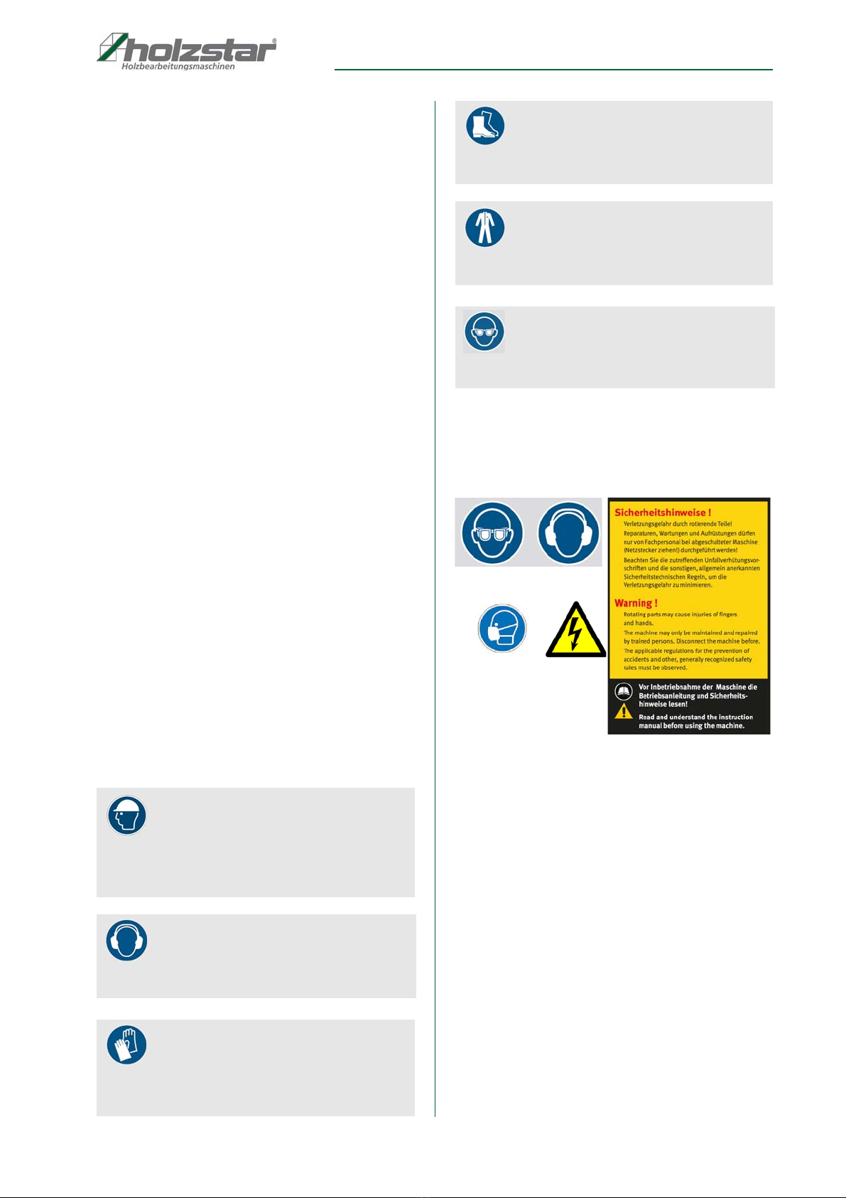
- Wear tight-fitting work clothing, safety glasses,
safety shoes and hearing protection. Tie long hair to-
gether. Do not wear watches, bracelets, chains,
rings or gloves (rotating parts!) when working.
- Immediately eliminate any faults that impair safety.
- Never leave the machine unattended in operation
and remain with the machine until the tool has come
to a complete standstill. Then pull out the mains plug
to protect against unintentional switching on.
- Protect the machine from moisture (danger of short
circuits!).
- Never use electric tools and machines in the vicinity
of flammable liquids and gases (danger of explo-
sion!).
- Before each use of the machine, make sure that no
parts are damaged. Damaged parts must be re-
placed immediately to avoid sources of danger!
- Do not overload the machine! You will work better
and safer in the specified power range. Use the cor-
rect tool! Make sure that the tools are not blunt or
damaged.
- Only use original spare parts and accessories to
avoid possible hazards and accident risks.
2.7 Safety instructions for the lathes
- The machine must always be operated by qualified
personnel who are familiar with its operation and
function.
- Always wear eye protection.
- Securely fasten the wood to be processed
- Do not work with cracked or faulty wood
- Use the lowest speed after clamping a new work-
piece.
- Observe the warnings on the machine.
- The clamped material must not be too unbalanced to
prevent ejection.
- Before switching on the motor, turn the clamped
workpiece a few turns by hand to avoid collisions.
- Do not wear work gloves, as they can get caught on
the workpiece.
- Wear a dust mask to protect yourself from wood
dust.
- Prevent the tool from being hooked in during machi-
ning
- Place the tool on the support. Set the cutting edge of
the tool to the center of the workpiece.
- Pay attention to the correct direction of rotation.
- Remove all loose snags before switching on the unit.
- Always ensure that the machine is used and handled
safely.
NOTE!
The instructions for use and maintenance must be
read carefully before starting, using, servicing or
otherwise modifying the machine. Handling and wor-
king with the machine is only permitted to persons
who are thoroughly familiar with the handling and
mode of operation of the machine.
ATTENTION!
Repairs, maintenance and upgrades may only be
carried out by qualified personnel with the machine
switched off (pull the mains plug!)!
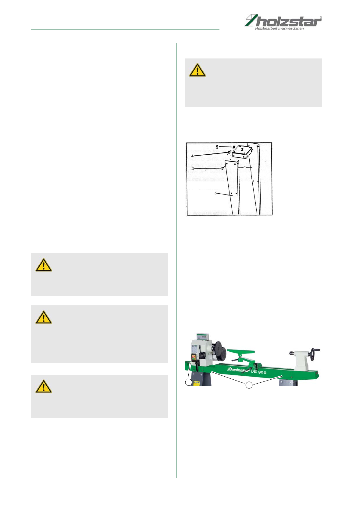
ATTENTION!
Make sure that the main switch is in the "OFF" posi-
tion when connecting the machine to the power sup-
ply in order to avoid unintentional switching on.

Intended Use
DB-Series | Version 3.09 7
3 Intended Use
The lathe DB-Series is used exclusively for turning wood
or wood-like materials. The maximum turning length and
the maximum diameter of the workpiece to be machined
(see chapter "Technical data") must be observed. It is
suitable for private use, not for industrial use. Intended
use also includes compliance with all information in
these instructions. Any use beyond the intended use or
any other use is considered misuse.
Stürmer Maschinen GmbH assumes no liability for con-
structive and technical changes to the lathe.
Claims of any kind due to damage due to improper use
are excluded.
3.1 Residual risks
Even if all safety regulations are observed and the ma-
chine is used in accordance with the regulations, there
are still residual risks, which are listed below:
- Injuries caused by flying work pieces or work piece
parts
- Fire hazard with insufficient ventilation of the motor
- Danger of electric shock, if the wiring is not correct.
- Danger from noise and dust (wear ear protection
and use a suitable extraction system).
4 Technical Data
WARNING!
Danger in case of misuse!
Misuse of the lathe can lead to dangerous situations.
- Only operate the lathe in the power range specified
in the technical data.
- Never bypass or disable the safety devices.
- Never work on materials other than those specified
for the intended use.
- Only operate the lathe in a technically perfect condi-
tion.
- Never machine several workpieces at the same
time.
ATTENTION!
Certain types of wood and wood products produce
harmful dust emissions when processed. Therefore,
only use your machine in a well-ventilated room and
preferably use an extraction unit.
ATTENTION!
The machine may only be operated in a technically
perfect condition. Any faults must be rectified imme-
diately.
Unauthorised modifications to the machine or impro-
per use of the machine as well as disregard of the
safety regulations or the operating instructions
exclude the manufacturer's liability for any resulting
damage to persons or objects and invalidate the war-
ranty claim!
WARNING!
It should be pointed out that every machine has resi-
dual risks. All operations (even the simplest ones)
must be carried out with great care. Safe working
depends on you!
Model DB 900
Max. turning Ø 306 mm
Max. height 153 mm
Max. width 900 mm
Spindle head thread M33 x 3.5
Morse cone MK 2
Speeds 500 - 2000 min-¹
Speed stages Mechanical variable,
10 stages
Motor output 550 W
Electrical connection 230 V / 50 Hz
Dimensions L x W x H 1380 x 330 x 1175 mm
Weight 80 kg
Model DB 1100
Max. turning Ø 358 mm
Max. height 179 mm
Max. width 1100 mm
Spindle head thread M33 x 3.5
Morse cone MK 2
Speeds 500 - 2000 min-¹
Speed stages Mechanical variable,
10 stages
Motor output 750 W
Electrical connection 230 V / 50 Hz
Dimensions L x W x H 1620 x 340 x 1215 mm
Weight 92 kg

8DB-Series | Version 3.09
Transport, packaging, storage
4.1 Type plate
Fig. 2: Type plate DB 1100
5 Transport, packaging, storage
5.1 Delivery
After delivery, check the lathe for visible transport da-
mage. If you discover any damage to the lathe, report it
immediately to the transport company or dealer.
Transport
Improper transport is accident-prone and can cause da-
mage or malfunctions for which we do not grant any liabi-
lity or guarantee.
Transport the scope of delivery secured against shifting
or tilting with a sufficiently dimensioned industrial truck to
the installation site.
General risks during internal transport
Devices may only be transported by authorized and qua-
lified persons. Act responsibly during transport and al-
ways consider the consequences. Refrain from daring
and risky actions.
Gradients and descents (e.g. driveways, ramps and the
like) are particularly dangerous. If such passages are
unavoidable, special caution is required.
Before starting the transport check the transport route for
possible danger points, unevenness and disturban-ces
as well as for sufficient strength and load capacity.
Danger points, unevenness and disturbance points must
be inspected before transport. The removal of danger
spots, disturbances and unevenness at the time of trans-
port by other employees leads to considerable dangers.
Careful planning of internal transport is therefore essen-
tial.
Transport with a forklift/lift truck:
For shipping, the device packed in a wooden box is deli-
vered on a pallet so that it can be transported with a
forklift truck or pallet truck.
5.2 Packaging
All of the machine‘s packaging materials and packing
aids are suitable for recycling and must always be dispo-
sed of using material-based recycling systems.
Packaging materials made of cardboard must be shred-
ded and disposed of as part of waste paper recycling.
The foils are made of polyethylene (PE), padding is
made of polystyrene (PS). Dispose of these substances
at a recycling centre or hand them over to the relevant
waste disposal company.
5.3 Storage
Let the lathe cool down completely. Storage the thoro-
ughly cleaned lathe in a dry, clean and frost-free environ-
ment.
Environmental temperature range: -25 °C to +55 °C.
WARNING!
Severe or fatal injuries may occur if parts of the
machine tumble or fall down from the forklift
truck, pallet truck or from the transport vehicle.
Follow the instructions and information on the trans-
port box.
Note the total weight of the machine. The weight of
the machine is indicated in the "Technical data" of the
machine. When the machine is unpacked, the weight
of the machine can also be read on the rating plate.
Only use transport devices and load suspension gear
that can hold the total weight of the machine.
WARNING!
The use of unstable lifting and load suspension
equipment that might break under load can cause
severe injuries or even death. Check that the lifting
and load suspension gear has sufficient load-bea-
ring capacity and that it is in perfect condition.
Observe the accident prevention regulations issued
by your Employers Liability Insurance Association or
other competent supervisory authority, responsible
for your company.
Fasten the loads properly.
WARNING: DANGER OF TIPPING
The device may be lifted unsecured by a maximum
of 2cm.
Employees must be outside the danger zone, the
reach of loads.
Warn employees and, if necessary, advise employ-
ees of the hazard.

Description of the device
DB-Series | Version 3.09 9
6 Description of the device
6.1 Machine
Illustrations in these operating instructions may de-
viate from the original.
Fig. 3: Lathe DB 900
1. Bed extension
2. ON/OFF, EMERGENCY STOP switch
3. Speed adjustment lever
4. Digital display of speed
5. Spindle head
6. Face plate
7. Motor
8. Tool rest
9. Clamping lever, tool rest arm
10. Machine bed
11.Travelling centering point
12. Tailstock
13. Handwheel
14. Tailstock spindle clamp
15. Tailstock - clamping lever
16. Machine base frame
17. Tool rest
18. Clamping, tool rest
19. Clamping, height adjustment of the tool rest
20. Locking bolt
21. Clamping lever for spindle head
6.2 Scope of delivery
- Wood Lathe
- Base frame
- Face plate, diameter 15 cm
- Travelling tailstock centre
- Face driver
6.3 Accessories, not included
Fig. 4: Accessories
12 3 4576 8 9
10
12
14
13
15
11
16
17
19
18
20
21
Description Item
No.
1. 8-part turning tool set 5931011
2. 4-jaw chuck set 1 Ø 150 mm, M33x3.5 5931020
3. 4-jaw chuck set 1 Ø 100 mm, M33x3.5 5931021
4. 4-jaw chuck set 2 Ø 100 mm, M33x3.5 5931023
5. Copy device for DB 1100 5931102
Copy device for DB 900 5931101
6. Fixed steady DB1100 5931030
Fixed steady DB 900 5931050
7External turning device DB1100 5931052
8. Carrier Set MK3. 3 pieces DB 900 and
DB 1100
5931056
1 2
34
5
6
7

10 DB-Series | Version 3.09
Installation and connection
7 Installation and connection
7.1 Requirements for the place of in-
stallation
The Wood lathe must be placed securely on a level and
firm surface. It must be ensured that there is sufficient
freedom of movement for working. The installation site
should meet the following criteria:
- The surface must be level, firm and free of vibrati-
ons.
- The substrate must not allow any lubricants to pass
through.
- The installation or work area must be dry and well
ventilated.
- No machines causing dust or chips should be opera-
ted near the machine.
- There must be sufficient space for the operating per-
sonnel, for material transport and for adjustment and
maintenance work.
- The place of installation must have good lighting.
7.2 Setting up the lathe
The lathe is supplied in a wooden box and is already lar-
gely assembled. Only a few parts have to be assembled
after delivery.
8 Mounting
8.1 Model DB 900
8.1.1Assembly of the machine frame
Fig. 5: Assembly of the machine frame
The machine frame is prepared for operation with the
following steps:
Step 1: Screw the frame feet (Pos.1, Fig.5) to the bracket
(Pos.2, Fig.5) using 3 M8x12 round head
screws (Pos.3, Fig.5) and the corresponding
washers (Pos.4, Fig.5) and nuts (Pos.5, Fig.5).
Step 2: Attach the tool rest to the intended position
(Pos.6, Fig.5) with a total of 8 M8x12 round
head screws, washers and nuts.
8.1.2Assembly of the machine bed
Fig. 6: Assembly of the machine bed
Place the machine frame on a level work surface.
Lift the machine onto the machine frame with the aid of a
second person. Fasten it with 8 M8x35 hexagon socket
screws (Pos.1, Fig. 6). Place a spring washer under
each nut.
The machine bed extension (Pos.2, Fig.6) must also be
mounted. Tighten it with two hexagon socket screws
M10x25 and spring washers.
CAUTION!
Risk of injury from an unstable machine!
Check the stability of the machine after setting it up
on stable ground.
CAUTION!
Observe the weight of the machine!
The machine may only be set up by two persons
together.
Check the appropriate aids for adequate dimensio-
ning and load capacity.
ATTENTION!
In order to ensure sufficient stability of the machine, it
should be bolted to the ground. For this purpose there
are 4 holes at the bottom of the machine frame.
ATTENTION!
During assembly, the parts must first be loosely
screwed together. When all parts are assembled,
align the parts at right angles before tightening the
screws.
1
2

Operation
DB-Series | Version 3.09 11
8.1.3Mounting of spindle head
Fig. 7: Mounting of spindle head
Fix the spindle clamping lever (Pos.1, Fig.7) of the DB
900 in the following order: clamping handle, compres-
sion spring and screw.
8.2 Model DB 1100
8.2.1Assembly of the machine base
Fig. 8: Assembly of the machine bases
Attach the support plate (Pos.1, Fig 8) as shown in the il-
lustration. This requires the 4 hexagonal bolts, washers
and nuts supplied (Pos. 2, Fig. 8).
8.2.2Assembly of the machine bed
Place the machine base on a level work surface.Lift the
machine onto the machine frame with the aid of a second
person. Attach it with 8 hexagon socket screws M 8x35
(Pos.3, Fig. 8). Place a spring washer under each nut.
8.2.3Mounting of spindle head
On the DB 1100, the clamping lever (Pos. 1, Fig. 9) must
be screwed into the back of the spindle head.
Fig. 9: Mounting of spindle head
8.3 Electrical connection
Step 1: Insert the power plug into a 230 V socket.
Step 2: The machine is now ready for operation.
9 Operation
1
3
1
2
1
DANGER!
Risk of death due to electric shock!
Contact with live components may result in fatal
injury. Switched-on electrical components can make
uncontrolled movements and lead to serious injuries.
ATTENTION!
All work on the electrical installation may only be car-
ried out by a qualified electrician.
NOTE ON LUBRICATION!
All moving parts must be lubricated before commis-
sioning. The belt cover must be removed to lubricate
the selector and drive shafts. Only an adhesive
grease may be used here, otherwise it can lead to
malfunctions!
In addition, guides, quills and bearings must be lubri-
cated with commercially available grease.
WARNING!
Danger to life!
There is a danger to life for the operator and other
persons if they do not observe the following rules.
- The lathe may only be operated by an instructed
and experienced person.
- The operator must not work when under the influ-
ence of alcohol, drugs or medication.
- The operator must not work if he is overtired or suf-
fers from illnesses affecting his concentration.
- The lathe may only be operated by one person.
Other persons must stay away from the work area
during operation.
DANGER!
Risk of death due to electric shock!
Contact with live components may result in fatal
injury. Switched-on electrical components can make
uncontrolled movements and lead to serious injuries.
- Disconnect the mains plug before making any adju-
stments to the machine.

12 DB-Series | Version 3.09
Operation
9.1 Speed adjustment
Change the speed only when the motor is running!
To change the speed, the setting lever must be tightened
slightly to release it from its locked position. The desired
speed can be read on the digital display. Make sure that
the setting lever clicks into place again after adjustment.
The speed depends on the following factors:
- Type and nature of woods
- Glued woods
- Dimensions, such as diameter and length of the
workpiece
- Workpieces with large unbalance
- Dry or seasoned woods
- Lathing tools
- Lathe technology
Select a low speed for:
- Large diameter workpieces
- Glued workpieces
- Long workpieces
- Unbalanced workpieces
- Hard workpieces
9.2 Handling the clamping tools
Fig. 10: Handling the clamping tools
Mounting the face plate
Screw the face plate hand-tight onto the main spindle. In-
sert the rod (Pos.1, Fig. 10) into the compatible hole in
the faceplate and hold the main spindle in place using
the open-end wrench (Pos. 2, Fig. 10). Tighten the face
plate firmly to avoid loosening during operation.
Replacement of the face driver
Insert the face drivers manually into the main spindle. To
loosen it again, insert the rod (Pos.1, Fig. 9) at the back
of the main spindle and carefully knock out the face
driver. Hold it firmly to prevent it from falling down and
getting damaged.
Use the face driver only for work "between lace".
Replacing the travelling tailstock centre
Fig. 11: Replacing the travelling tailstock centre
Release the clamping lever for the spindle clamping
(Pos. 1, Fig. 11). Turn the spindle on the handwheel (
Pos. 2, Fig. 11) completely backwards to remove the tail-
stock centre (Pos. 3, Fig. 11).
9.3 Adjustment of the spindle head
Release the spindle head clamp and pull the locking bolt.
Swivel the spindle head to the desired angle. The pos-
sible locking positions are 60°, 90°, 120° and 180°. As
soon as the spindle head is in the correct position, it
must be clamped again.
CAUTION!
Danger of crushing!
Improper work on the machine may result in injury to
the upper limbs
ATTENTION!
Before starting up, check the electrical connection,
cables and contacts.
Use hearing protection!
Wear safety boots!
Wear protective clothes!
Use eye protection!
ATTENTION!
Do not turn the spindle head more than 180° clock-
wise. Damage to the power cable may result.
1
2
1
2
3

Operation
DB-Series | Version 3.09 13
Fig. 12: Adjustment of the spindle head
Step 1: Do not turn the spindle head counterclockwise
when it is in this position (Pos. 1, Fig.12).
Step 2: Do not turn the spindle head clockwise when it is
in this position (Pos. 2, Fig.12).
With the lathe DB 1100, you also have the option of mo-
ving the spindle head on the machine bed after releasing
the spindle head clamp (Figure 13).
Fig. 13: Move the spindle head.
9.4 Adjustment of the tailstock
Fig. 14: Adjustment of the tailstock
After releasing the tailstock clamping lever (Pos. 1, Fig.
14), the tailstock can be moved on the machine bed as
required.
To clamp a long workpiece between centres, clamp the
tailstock to the clamping lever (pos. 1, Fig. 14). Turn the
tailstock spindle on the handwheel out until the travelling
centering point is pressed sufficiently deep into the work-
piece to be machined. This should protrude approx. 20
mm from the tailstock. Clamp the spindle to the lever
(Pos. 3, Fig. 14). Check by hand whether the workpiece
is firmly seated.
9.5 Adjusting the tool rest
Fig. 15: Adjusting the tool rest
Use the tool rest for safe guidance of the lathe tool and
as a support for the hand. A distance of approx. 1-3 mm
must be set between the workpiece and the tool rest. Ad-
just the tool rest approx. 3 mm below the axis of rotation.
Thinner workpieces can also be worked without an ex-
tension arm (Pos.1, Fig.15). Insert the tool rest (Pos.2,
Fig.15) directly into the traverse slide (Pos. 3, Fig. 15).
By releasing the clamping lever (Pos.4, Fig.15), the travel
carriage can be moved on the machine bed as required.
When machining larger workpieces, the tool rest with ex-
tension arm must be mounted to the left of the headstock
(Figure 16).
Fig. 16: Tool rest mounted left
Finally tighten all clamping levers.
Turn the workpiece several times by hand to check the
settings and avoid collisions.
Work instruction
NOTE!
Adjust the lace from time to time during machining to
12
1
2
3
NOTE!
For an optimal lathe turning result, perfect and shar-
ply ground tools must be used.
1
2
3
4

14 DB-Series | Version 3.09
Care, maintenance and repair
Choice of materials
Defective wood tends to splinter and becomes a risk for
user and machine.
Work pieces made of glued wood should only be proces-
sed by an experienced craftsman. Turning these woods
requires careful gluing without weak points, as the work-
piece can explode due to the centrifugal force generated.
The user should master the basic knowledge of turning
with solid material.
Material preparation
For turning of the log wood, the material must first be cut
to a square shape.
For turning crosswise wood, the material must also be
cut raw. You can, for example, saw out the crossbar raw
with a band saw. An octagonal shape is suitable to avoid
vibrations.
Center workpiece
The centering of the prepared workpieces is an import-
ant operation before they are inserted into the machine.
Centering means measuring the center of the workpiece,
marking it with center punches and making a recess of
1.5 to 2 mm in diameter in the center. If the workpiece is
not centered exactly, the unbalance will cause excessive
vibrations. This can result in the workpiece being
ejected. A clean concentric run can only be achieved by
exact centering of the workpiece.
During turning
The unmachined part must be machined at low speed.
After pre-turning, i.e. when the basic shape of the work-
piece has been achieved and uniform concentricity has
been achieved, the speed can be increased. The rotating
center of the center punch must be readjusted by means
of the handwheel when the motor is switched off. The
centre poin of the grain must sit firmly in the wood. Turn
the workpiece by hand to check the tight fit between the
tips.
Technical literature
The specialized trade offers literature about turning. It is
a great help for beginners and experts and also contains
many suggestions for processing.
10 Care, maintenance and repair
10.1Care by cleaning
Step 1: Disconnect the mains plug from the socket.
Step 2: Remove chips and dust from the machine with a
hand brush or brush.
Step 3: Check the machine for damage to the safety de-
vices. If necessary, carry out or arrange for the
repair to be carried out in accordance with the
safety instructions.
10.2Maintenance
Maintenance and repair work may only be carried out by
qualified personnel.
If the lathe does not function properly, contact a specia-
list dealer or our customer service. The contact details
can be found in chapter 1.2 Customer Service.
Please consider the following points:
1. All protective and safety devices must be reinstalled
immediately after completion of repair and main-
tenance work.
2. Clean the spindle thread for the tool holder when
changing tools and oil it lightly.
DANGER!
Risk of death due to electric shock!
Contact with live components may result in fatal
injury. Switched-on electrical components can make
uncontrolled movements and lead to serious injuries.
- Before starting cleaning and maintenance work,
switch off the machine and disconnect the mains
plug.
- Connections and repairs to the electrical equipment
may only be carried out by a qualified electrician.
Use protective gloves!
NOTE!
Never use strong cleaning agents for any cleaning
work. This can damage or destroy the device.
ATTENTION!
Do not remove the chips with your hand. There is a
risk of cutting injuries from chips and tools!

Troubleshooting
DB-Series | Version 3.09 15
3. Occasionally unscrew the tailstock spindle, clean it
and spray it with dry lubricant. Grease the threaded
spindle.
4. Check the clamping of the tailstock and tool rest and
readjust if necessary.
5. Check drive belt and replace if necessary. The check
should be carried out after approx. 100 operating
hours.
10.3Servicing
As a result of wear and tear, servicing work may have to
be carried out on the machine.
Lubrication
The belt cover must be removed to lubricate the shift and
drive shafts. Only an adhesive grease may be used for
t h i s , a s i t c a n o t h e r w i s e l e a d t o m a l f u n c t i o n s o f t h e b e l t !
Guides, quills and bearings must be lubricated with com-
mercially available grease!
The points to be lubricated are shown in Figure 17.
Fig. 17: Lubricating points
11 Troubleshooting
ATTENTION!
Servicing work may only be carried out by qualified
personnel with mechanical knowledge.
NOTE!
During the maintenance of the lathe, all moving parts
must be lubricated at least once a month. If required,
the parts can be lubricated at shorter intervals
Lubricating points
Fault Possible cause Solution
Motor does not start No mains voltage. Check mains fuse.
Switch, capacitor are defec-
tive.
Have checked by a qualified electrician.
Electrical extension conduc-
tor is defective.
Pull the mains plug, check and replace if necessary.
Holes become larger
than the drill used.
Spindle head and tailstock
are not parallel.
Adjust spindle head to tailstock tip. To do this, insert the
face driver and the moving tailstock tip. Push the tailstock
forward and align with the points.
The workpiece is flut-
tering
Workpiece loosens during
work.
Observe the working instructions in the operating instructi-
ons.
No centering. Observe chapter "Working instructions" in the operating in-
structions.
Speed too high. Select a lower speed.
The tool rest or the
tailstock can no lon-
ger be clamped..
The eccentric clamp is too
loose.
Tighten the hexagon nuts on the underside. This only has
to be in contact and not tightened.

16 DB-Series | Version 3.09
Disposal, reusing used machines
12 Disposal, reusing used ma-
chines
In your own interest and to protect the environment make
sure that all machine components are exclusively dis-
posed of in as intended and permitted.
12.1Decommissioning
Disused machines must be decommissioned immedi-
ately to prevent misuse at a later point and putting the
environment or persons at risk.
Step 1: Remove all environmentally hazardous process-
ing materials from the used machine.
Step 2: If necessary, disassemble the machine into as-
semblies and components that are easy to han-
dle and suitable for recycling.
Step 3: The machine components and processing mate-
rials must be disposed of using the intended dis-
posal methods.
12.2Disposal of electrical equipment
Note that electrical equipment contains a variety of recy-
cling-capable materials and also environmentally haz-
ardous components.
Please help to separate these components and dispose
of them responsibly. In case of doubt, contact your local
waste disposal authority. Consult a specialist disposal
agent for recycling if needed.
12.3Disposing of lubricants
Lubricant manufacturers provide disposal information for
the lubricants used. If necessary, request product-spe-
cific data sheets.
Strong vibrations. Workpiece deformed, un-
round, has large weak points/
cracks or has not been prepa-
red for turning.
Prepare the workpiece for turning by planing and sawing.
Spindle bearing is worn. Replace the spindle bearing.
Belt is worn. Replace the belt
Motor mounting or handle are
loose.
Tighten screws and handle.
The lathe stands on an une-
ven surface.
Place the lathe on a flat surface and align it.
The workpiece sur-
face is too rough.
The turning iron is out of fo-
cus.
Resharpen the turning iron.
Turning iron spring Clamp the lathe tool shorter.
Motor overheats and
has no power
Motor overloaded. Reduce feed.
Mains voltage is too low Switch off and have it checked by a specialist.
Motor is connected incor-
rectly.
Have it checked by a specialist.
Insufficient working
accuracy
Uneven, heavy or clamped
workpiece.
Clamp workpiece mass-balanced and tension-free.
Incorrect horizontal position
of the tool rest.
Adjust the tool rest.
Fault Possible cause Solution

Spare parts
DB-Series | Version 3.09 17
12.4Disposal via municipal collection
points
Disposal of used electrical and electronic equipment
(Applicable in the countries of the European Union and
other European countries with a separate collection sys-
tem for these appliances).
The symbol on the product or its packaging indi-
cates that this product should not be treated as normal
household waste, but must be returned to a collection
point for the recycling of electrical and electronic equip-
ment. By helping to properly dispose of this product, you
are protecting the environment and the health of others.
Environment and health are endangered by improper
disposal. Material recycling helps to reduce the con-
sumption of raw materials. For more information about
recycling this product, contact your local community, mu-
nicipal waste management, or the shop where you pur-
chased the product.
13 Spare parts
13.1Spare parts orders
Spare parts are available from authorised retailers or di-
rectly from the manufacturer. The contact details have
been listed in section 1.2 Customer service.
The following key data is required for queries or spare
parts orders:
- Device type
- Item number
- Position number
- Year of construction
- Quantity
- Desired shipping type (post, freight, sea, air, ex-
press)
- Shipping address
Spare parts orders without the aforementioned data can-
not be taken into account.
The supplier shall determine the shipping type if no rele-
vant data was provided. Data on the machine type, item
number and year of manufacture is listed on the type
plate attached to the device.
Example
The handwheel for the Wood Lathe DB 900 must be or-
dered. The handwheel has the number 49 in the spare
parts drawing 1.
By ordering spare parts, send a copy of the spare parts
drawing (1) with the marked part (handwheel) and mar-
ked positon number (49) to the dealer or spare parts de-
partment and provide the following information:
- Type of device: Wood Lathe DB 900
- Item number: 5920900
- Drawing number: 1
- Position number: 49
DANGER!
Risk of injury caused by the use of
incorrect spare parts!
The use of incorrect or faulty spare parts may cause
risks for operating staff and damage as well as mal-
functions.
- Exclusively genuine spare parts made by the manu-
facturer or spare parts authorised by the manufac-
turer shall be used.
- Always contact the manufacturer if you are unsure.
NOTE!
The manufacturer warranty shall be rendered void in
the event of a use of unauthorised spare parts

18 DB-Series | Version 3.09
Spare parts
13.2Spare parts drawing DB 900
The following spare parts drawings is intended to help identify the necessary spare parts. To order, please send a copy of
the list of spare parts with the marked components to your dealer.
Fig. 18: Spare parts drawing DB 900

Spare parts
DB-Series | Version 3.09 19
13.3 Spare parts drawing DB 1100
Fig. 19: Spare parts drawing DB 1100

20 DB-Series | Version 3.09
Electrical circuit diagram
14 Electrical circuit diagram
Fig. 20: Electrical circuit diagramEC Declaration of Conformity
Other manuals for DB 900
3
This manual suits for next models
1
Table of contents
Other Holzstar Lathe manuals