HOMCOM C20-010 User manual

ASSEMBLY INSTRUCTION
INag004V01_DE
C20-010
IMPORTANT, RETAIN FOR FUTURE REFERENCE: READ CAREFULLY
Benutzer-Handbuch für QZ-6803A Zündpistole

1
23
4
5
Fig. 1-1
I.Bildbeschreibung für alle Teile der Zündpistole
1. Xenonlampe (leuchtet während der Dauer der Prüfzeit)
2. Blitzfrequenz-Schalter ( drücken sie den Schalter um die Blitzfrequenz zu starten und
lassen sie ihn los um ihn sie zu beenden)
3. Induktive Signalaufnahme ( Verbindung zum Hochspannungsleiter zum Zylinder)
4. Rote Batterieklemme (Verbindung zur Batterie-Anode “+“)
5. Schwarze Batterieklemme ( Verbindung zur Batterie-Anode “-„)
II. Vorbereitung vor der Verwendung
2-1 Bevor sie einen Test starten, prüfen sie bitte vorab ob es technische Probleme gibt.
Z.B lose Verbindungen oder Beschädigungen am Gehäuse, Kabel oder Verbindungen
können zu einer Störung des Motorbetriebs führen.
2-2 Folgen sie der Reperaturanleitung. Prüfen sie vorab die Unterdruckleitung und ob die
Kabel richtig in den Verbindungen sitzen. Danach prüfen sie folgende Teile:
Alle Flüssigkeitsstände / Zündkerzen du Hochspannungskabel / Luftfilter /
Unterdruckleitung / Keilriemen /
Schaltung / Schlussstecker
2-3 Ü berprüfung des Zündzeitpunktes des Motors:
2-3-1 Bevor sie den Zündzeitpunkt prüfen, checken sie den Motor. Prüfen sie die
Steuerplatte des Fahrzeugs oder testen sie das Verfahren. Die technischen Anforderungen
für die Zündung finden sie in der Reperaturanleitung.
Die Steuerplatte befindet sich im Motorraum. In der Regel befindet sich diese: an der
Rückseite der Motorhaube / an der Oberseite der Ventilkammer.
2-3-2 Folgen Vorbereitungen sind zwingend notwendig:
Finden sie die Zeitskala und die Position des Indikators. Die Zeitskala und der Indikator
befinden sich in der Regel an der Kurbelriemenscheibe, am Kurbelschwingungsdämpfer
(vorne am Motor), oder am Schwungrad.
-2-

Die Zeitskale und Anzeige sollte sauber und klar sein. Verwenden sie Kreidestaub falls
notwendig. Wenn alle Zündkerzen normal laufen und der Abstand der Elektroden
eingehalten ist , starten sie den Motor und lassen ihn auf Betriebstemperatur laufen.
Schalten sie den Motor aus, bevor sie die Zündpistole anschließen.
III. Anschluss der Zündpistole
Um eine sicheren Umgang mit der Zündpistole zu gewährleisten, schließen sie die Pistole
wie folg an:
WARNUG: halten sie ihre Hände, die Zündpistole, Verbindungskabel und den Empfänger
vom laufenden oder heißen Motorteilen fern. NICH RAUCHEN WÄHREND DER ARBEIT-
EN.
3-1 Schalten sie die Zündung aus. Schließen sie die Zündpistole niemals bei laufendem
Motor an oder wenn die Zündung an ist.
3-2 Achten sie darauf, das die Batterieklemmen mit keinen anderen Teilen, außer den
Anoden, in Berührung kommen. Stellen sie sicher, dass die Signalaufnahme mit keinen
heißen Motorteilen in Berührung kommt.
3-3 Befestigen sie die Klemmen an den vorgesehenen Stellen an der Batterie.
Die rote Klemme an die Anode “+“
Die schwarze Klemme an die Anode “-“
Fig. 2 Common timing marks
Induktive Signalaufnahme Hochspannungskabel (Zylinder)
Motor
Verbindung von der Signalaufnahme und dem
Hochspannungskabel
-3-

IV. Inspektion der Basiszündpunkte
Note: Bei einigen Systemen müssen sie vor der Prüfung oder Anpassung der
Zündzeitpunkte, entsprechend der Anweisung, einige Elemente geerdet sind. Wenn dies
nicht gewährleistet ist kann die korrekte Einstellung des Zündzeitpunts nicht gewährleistet
werden.
4-1 Stellen sie sicher, dass die Zündpistole an den richtigen Punkten angeschlossen ist.
4-2 Stellen sie sicher, dass Motor nach den obigen Anforderung eingestellt ist.
4-3 Starten sie den Motor und bringen sie ihn auf die normale Betriebstemperatur.
4-4 Falls erforderlich, lassen sie den Motor im Leerlauf laufen, bis die Temperatur erreicht
ist.
4-5 Stellen sie sicher das die Zeitpunktleuchte vorab „0“ anzeigt. Falls nicht drücken sie
den Erhöhen- / Verringern-Knopf, bis die Anzeige „0“ anzeigt. (Dies gilt für das Modell
QZ-6803 B, für Modell A ist dieser Schritt nicht notwendig)
4-6 Beachten sie die Position zw. der Zeitskala und der Anzeige: Vergleichen sie Anzeige-
grad mit dem spezifischem Wert. Wenn die Anzeigewerte innerhalb des zulässigen Bere-
ichs ( normalerweise +/- 2 Grad) liegen, ist die Zündung normal. Sollten die Werte außerh-
alb dieser Skala liegen, müssen Teile ausgewechselt werden oder der Zeitpunkt muss
angepasst werden.
4-7 drücken sie den Blitzschalter und lösen sie das Blitzlicht aus.
4-8 schalten sie die Zündung aus und nutzen sie die Zeitmessung.
Notiz: sollte die Zeitmessung nicht normal funktionieren, lesen sie bitte die Fehlerbehebun-
gen aus diesem Handbuch und prüfen auf mögliche Fehlerquellen.
V. Einstellung des Zündzeitpunkts
Stellen sie den Zündzeitpunkt entsprechend des Einstellungsverfahren und der tech-
nischen Anforderungen dieses Handbuchs ein. Stellen sie es nie ein, wenn die hier aufge-
listeten Anforderungen nicht gegeben sind.
Einstellung der Zeitmarke
Referenzindikator ablesen der Zeitaufnahme
-4-

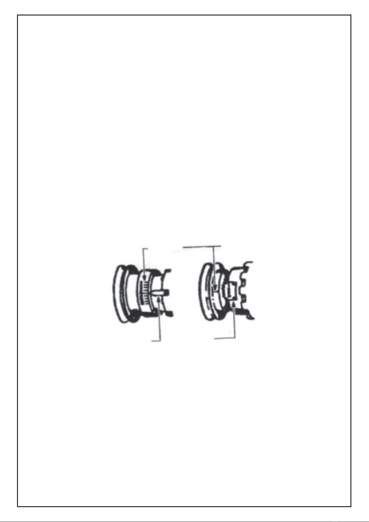
VI. Prüfung des Steuerteils der Vorzündung
Um die Kontrolle der Vorzündung zu gewährleisten, dass das Zündsystem während des
Zeitpunkts des Kompressionsschubes zündet. Die Steuerung der Frühzündung umfasst:
mechanische
Vorschubsteuerung, Unterdrucksteuerung und elektronische Vorsteuerung, etc.
Notiz: diese Prüfmethoden des Fahrzeugzündung sind sehr unterschiedlich. Die folgende
Methode ist die allgemeinste Methode für eine mechanische Inspektion des Zündpunktes.
Wenn sie Zündung prüfen sollten sie gucken, dass die Zündungszeit und der Schließwin-
kel korrekt sind. Siehe Reparaturanleitung, um das korrekte Kontrollverfahren einzusehen.
Achten sie darauf, das alle Sicherheitshinweise eingehalten sind.
VII. Inspektion der elektronischen Frühzündung
Die Ü berprüfung der elektronischen Zündvorstellung variiert von Fahrzeug zu Fahrzeug.
Entnehmen sie dies bitte aus dem Handbuch.
VIII. Fehlerbehebung der Zeitmessung
Wenn die Zeitmessung nicht richtig arbeitet, prüfen sie bitte folgende Teile.
8-1 Stellen sie sicher, das die Verbindung zw. den Klemmen und den Batteriepolen
gewährleistet ist.
8-2 Stellen sie sicher, das die Klemmen mit den richtigen Batteriepolen verbunden ist ( die
rote Klemme muss mit der “+“ Anode verbunden sein und die schwarze Klemme mit der “-“
Kathode)
8-3 Stellen sie sicher das die Anschlüsse frei von Schmutz sind. Wenn nötig befreien sie
diese von Schmutz, entsprechend auch die Anschlüsse der Zündpistole.
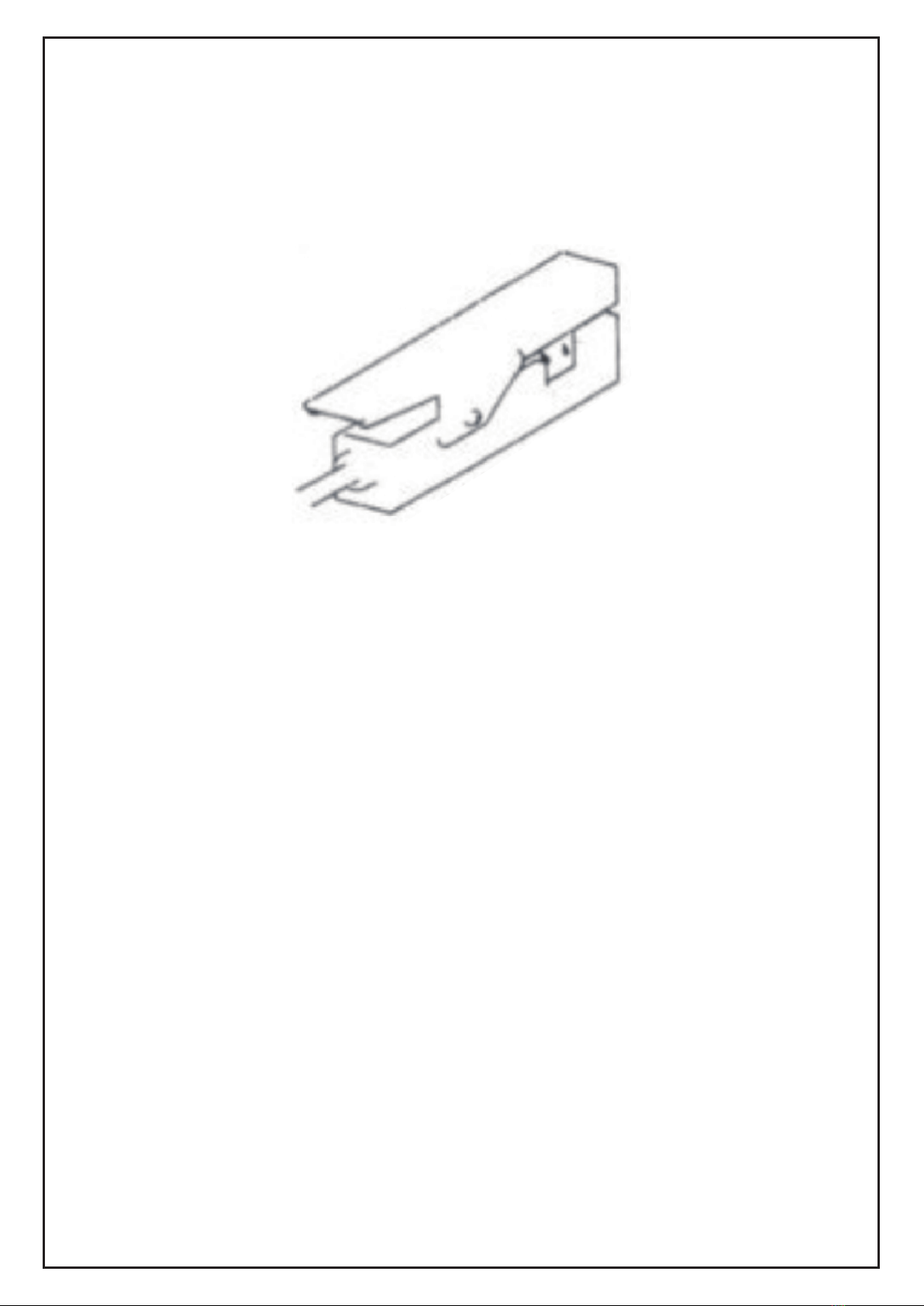
8-4 Stellen sie sicher das das induktive Signalaufnahmegerät korrekt mit dem Hochspan-
nungskabel und Zylinder 1 verbunden ist.
8-5 Stellen sie sicher, das die Zündkerze aus Zylinder 1 funktioniert.
8-6 Verbinden sie das induktive Signalaufnahmegerät mit dem Hochspannungskable aus
Zylinder 1.
Drücken sie den Schalter für das Prüflicht, prüfen sie die Zündkerze von Zylinder 1 und
führen folgen Anweisung durch.
Notiz: Stimmt etwas mit der niedrigen Zündspannung der Zündkerze oder dem Hochspan-
nungskabel nicht kann es zu Abweichungen der Zeitmessung führen. Klemmen sie die
induktive Signalaufnahmevorrichtung an anderen Positionen des Hochspannungskabels
an um zu prüfen ob sich die Daten ändern. Die elektromagnetischen Wellen, welche durch
die Zündung entstehen werden gemessen. Diese können bei Hochspannungskabeln für
z.B. Renn- oder Offroadfahrzeugen höher ausfallen als bei EMI oder RFI Standards.,
wodurch die Testwerkzeuge nicht korrekt arbeiten.
Kontaktieren für die richtigen Testanforderungen den Fahrzeughersteller.
-5-

IX. Pflegeanweisungen
Reinigen sie die induktive Signalaufnahmevorrichtung
Wenn die Oberfläche der induktiven Signalaufnahmevorrichtung verschmutzt z.B. durch Ö
lrückstände, kann die Zeitmessung nicht korrekt arbeiten. Reinigen sie die Oberfläche der
induktiven Signalaufnahmevorrichtung regelmäßig.
Reinigen sie die Kontakt-Oberfläche
-6-

User Manual for QZ-6803A Timing Light
-7-

1
23
4
5
Fig. 1-1
I. Introduction Picture for all Parts of the Timing Light
1.Xenon lamp (light the timing mark during checking the timing)
2.Flash frequency light switch (press this switch, the flash frequency light begins to flash,
when loosen, the flash stops)
3.Inductive signal pickup device (connect high voltage wire of cylinder 1)
4.Red battery jar clip (connect the battery anode + )
5.Black battery jar clip (connect the battery cathode - )
II. Preparation before the use of the timing light
2-1 Before any test, check carefully and eliminate all mechanical trouble. Loose connection
or damage of the pipe, wire, and connector will result in abnormal operation of the engine.
2-2 Follow the repair manual, check whether the vacuum pipeline, wire, and wire bunch
connector are correctly connected, then check the following parts:
all liquid level
spark plug and high voltage wire of the spark plug
air filter
vacuum pipeline
belt
circuit
circuit connector
2-3 Check the preparation of the ignition timing engine:
2-3-1 Before checking the ignition timing, make preparations of the engine, check the
discharge control plate of this vehicle or the test procedure and technical requirement for
the ignition timing in the repair manual. The discharge control plate of the vehicle is inside
the engine chamber, the usual position is: the back of the engine hood, the engine bulk-
head, the top of the valve chamber cover or near the engine hood lock.
2-3-2 Make the following preparations at least:
Find the timing scale and the position of the indicator. The timing scale and the indicator
are usually at the crank pulley, crankshaft vibration damper (at the front of the engine) or
the flywheel (between the engine and the transmission), etc. (see Fig. 2)
-8-

The timing scale and the indicator should be clean and clear. Apply chalk dust on them if
necessary. All the spark plugs work normally, the gap between the electrodes is correct.
Start the engine, run to the normal working temperature. Shut down the engine before
connecting the timing light.
III. Connecting the timing light
In order to ensure safety and reliable operation of the timing light, connect according to the
following steps:
Warning: keep hand, timing light, connecting wire and the signal pickup device away from
the running parts and the high temperature surface of the engine. No smoking.
3-1 Close the ignition switch. Never connect the timing light when the engine is running or
the ignition switch is turned on.
3-2 Clip the inductive signal pickup device to the high voltage wire of cylinder 1.(See Fig 3)
Make sure that the signal pickup device doesn't touch the discharge branch pipe or other
parts of the engine, as temperature on these parts can be very high when the engine is
running, which may damage the signal pickup device.
3-3 Clamp the battery jar clip at the battery jar inside the vehicle.
The red clip connects the anode (+)
The black clip connects the cathode (-)
Fig. 2 Common timing marks
Inductive signal
pickup device High voltage wire
of cylinder 1
Engine
Connection of the inductive signal pickup device and the high voltage wire
-9-

IV. Inspection of the basic ignition timing
Note: For some systems, before checking or adjusting the ignition time according to
instructions, some special elements should be unplugged, jump connected or grounded. If
it's not done according to instructions, the checked or adjusted ignition time will not be
correct.
4-1. Make sure that the timing light is correctly connected according to the above require-
ment.
4-2. Make sure the preparations of the engine have been made according to the above
requirement.
4-3. Start the engine, run to the normal working temperature.
4-4. If needed, adjust the idle speed according to the factory's requirement.
4-5. Make sure that the ignition advance angle indicated on the timing light is zero. If not,
press the increase/decrease button of the advance angle, to make the display of the
advance angle “zero” . (This applies to QZ-6803B timing light; Model A doesn't need this
step.)
4-6. Observe the relative position between the timing scale and the indicator (see Fig 4):
compare the displayed timing degrees with the specified value, if the timing degrees are
within the allowed range(usually ± 2 degrees), then, the ignition timing is normal. If the
degrees exceed the range, it's likely that some parts need to be replaced or the timing
needs to be adjusted.
4-7. Loose the flash switch, turn off the flash light.
4-8. Turn off the ignition switch, take down the timing light.
Note: If the timing light doesn't work or works abnormally, please refer to the trouble-elimi-
nation section of this manual, check the possible causes.
V. Adjustment of the ignition timing
Adjust the ignition timing according to the adjustment procedure and technical requirement
according to the repair manual. Never try to adjust the ignition timing when one is not sure
of the adjustment procedure and technical requirement.
Rotate the
timing mark
Reference
indicator Read of the timing record
-10-

VI. Inspection of the control part of the ignition advance
he control of the ignition advance is to guarantee that the ignition system can ignite at the
appropriate time during the compression stroke. The control of the ignition advance
includes: mechanical advance control, vacuum advance control, and electronic advance
control, etc.
Note: The inspection methods of the vehicle's ignition advance vary greatly. The following
mentioned method is the general method to inspect mechanical/centrifugal type ignition
advance. When checking the ignition advancing angle, one should confirm that the refer-
ence ignition time and the closing angle are correct. Refer to the repair manual to under-
stand correct inspection procedure and technical requirement.
Make sure that all the safety rules are observed.
VII. Inspection of the electronic ignition advance
The inspection of the electronic ignition advance control varies from vehicle to vehicle.
Please refer to the repair manual.
VIII. Trouble shooting of the timing lamp
If the timing light doesn't work or work abnormally, inspect the following items:
8-1. Make sure that the connection between the battery jar clip of the timing light and the
battery jar is reliable.
8-2. Make sure that the polarity connection between the battery jar clip of the timing light
and the battery jar is correct (the red clip should be connected to the anode “+” ,and the
black clip should be connected to the cathode“-”).
8-3. Make sure that the surface of the up/down ferrite magnetic block in the inductive signal
pickup device is clean. If necessary, clean the ferrite magnetic block according to the
section of the timing light maintenance and points for attention.
8-4. Make sure that the inductive signal pickup device is correctly connected to the high
voltage wire of cylinder 1.
8-5. Make sure that the spark plug of cylinder 1 works normally.
8-6. Connect the inductive signal pickup device to the high voltage wire of the other cylin-
der 1, press the flash frequency light, if the timing light flashes, check the spark plug of the
cylinder 1, and then conduct the following work.
Note: Anything wrong with the low ignition voltage of the spark plug and the high voltage
wire can result in the abnormal operation of the timing light. Clamp the inductive signal
pickup device at other places of the high voltage wire to see if things will change. The
electromagnetic wave produced by some ignition systems and special high voltage wires
(solid wire core high voltage wire, high voltage wire of racing vehicle, high voltage wire of
off road vehicle) is higher than EMI and RFI standards, thus the testing equipment can not
work normally. Contact relative manufacturers to learn the correct test requirement.
-11-

IX. Points for attention and maintenance
Clean the inductive signal pickup device
If the surface of the inductive signal pickup device is dirty or has oil stain, the timing light
may work abnormally. Clean the working surface of the inductive signal pickup device at
regular intervals. (see Fig. 6)
Clean the contact surface
Fig. 6 Clean the inductive signal pickup device
-12-
Table of contents
Languages:
Other HOMCOM Automobile Accessories manuals