Home Sentinel WA110 User manual

HOME SECURITY
SYSTEM
OWNER’S
MANUAL
INSTALLATION AND OPERATION
________________________________________________________________
BEFORE INSTALLING OR
OPERATING THE SYSTEM,
PLEASE READ THIS MANUAL,
MODELS : WA 110/ WA210/WA410/WA400
Distributed by:
Mansoor Electronics Ltd.
310 Alden Road, Markham
Ontario, Canada L3R 4C1
Tel: (905) 475-8444 Fax: (905) 475-3576
Toll Free: 1-800-268-9852
www.mansoorelectronics.com

•Read Instructions –All the safety and operating instructions should be read before
operating this equipment. These instructions should be retained for future reference
•Heed Warnings –All warnings on the equipment and in the operating instructions should
be adhered to. All instructions regarding care and operation of this equipment should be
followed.
•Power Sources –Equipment should only be connected to the power supply specified in
the operating instructions or as marked on the equipment.
•Grounding or Polarization –Take precautions that the equipment is properly grounded.
Take note that the power supply is fitted in the correct input jack ( marked DC 12V ), and
auxiliary units ( external siren and strobe light ) are fitted into the correct external jack
points.
•Power-Cord Protection –Keep cable cords and plugs clear of other objects, particularly at
the point where they exit the equipment.
•Cleaning –Clean the equipment by wiping with a soft cloth, ( do not use any abrasive
agents or water ).
•Non-use Periods –Power cords should be unplugged from the outlet when left unused for
a long period of time.
•Object and Liquid Entry –Take care not to drop objects or liquids on any part of the
equipment.
•Damage Requiring Service –The alarm should be serviced by a qualified service
personnel when:
-The power-supply cord or the plug has been damaged; or
-Objects have fallen, or liquid has been spilled onto the equipment; or
-The equipment has been exposed to rain; or
-The equipment does not appear to operate normally or exhibits a marked change in
performance; or
-The equipment has been dropped, and/or the enclosure has been damaged.
•Servicing –Do not attempt to service the appliance beyond that described in the operating
instructions. All other servicing should be referred to a Qualified Distributor’s Service
Personnel.
•System Maintenance –Under normal use your system requires virtually no maintenance
other than regular testing. It is recommended that you test your system once a week, and
replace the batteries at least onceevery 6 months ( or as needed ).
1
Important Safety Instructions
WARNING: TO REDUCE THE RISK OF FIRE OR ELECTRIC SHOCK,
DO NOT EXPOSE THIS APPLIANCE OR POWER ADAPTER TO WATER OR MOISTURE
IMPORTANT NOTE: IF YOU RETURN TO YOUR PREMISES AND FIND THAT THE ALARM
IS IN PROGRESS, DO NOT ENTER, AS A FIRE OR AN INTRUDER MAY BE PRESENT. GO
TO A NEIGHBOR AND CONTACT THE RELEVANT LOCAL AUTHORITIES FROM THERE.

Important Safety Instructions…………………………………………………1
Introduction………………………………………………………………3
About the Home Sentinel ® Security Alarm System..……………………………....3
Out of the Box…………………………………………………………….3
Planning for Installation…………………………………………………..…4
Choosing Locations………………………………………………..….4
System ID Codes…………………………………………………..…4
Setting & Changing System ID codes.………………………………..……4
Understanding Normal & Auto Modes……………………………………..5
24 Hour and Home-Away Functions……………………………………....6
Setting the Alarm Period.…………………………………………….…7
Alarm Delay Time………………………………..………………..….7
Installing the back-up battery………………………………………...….7
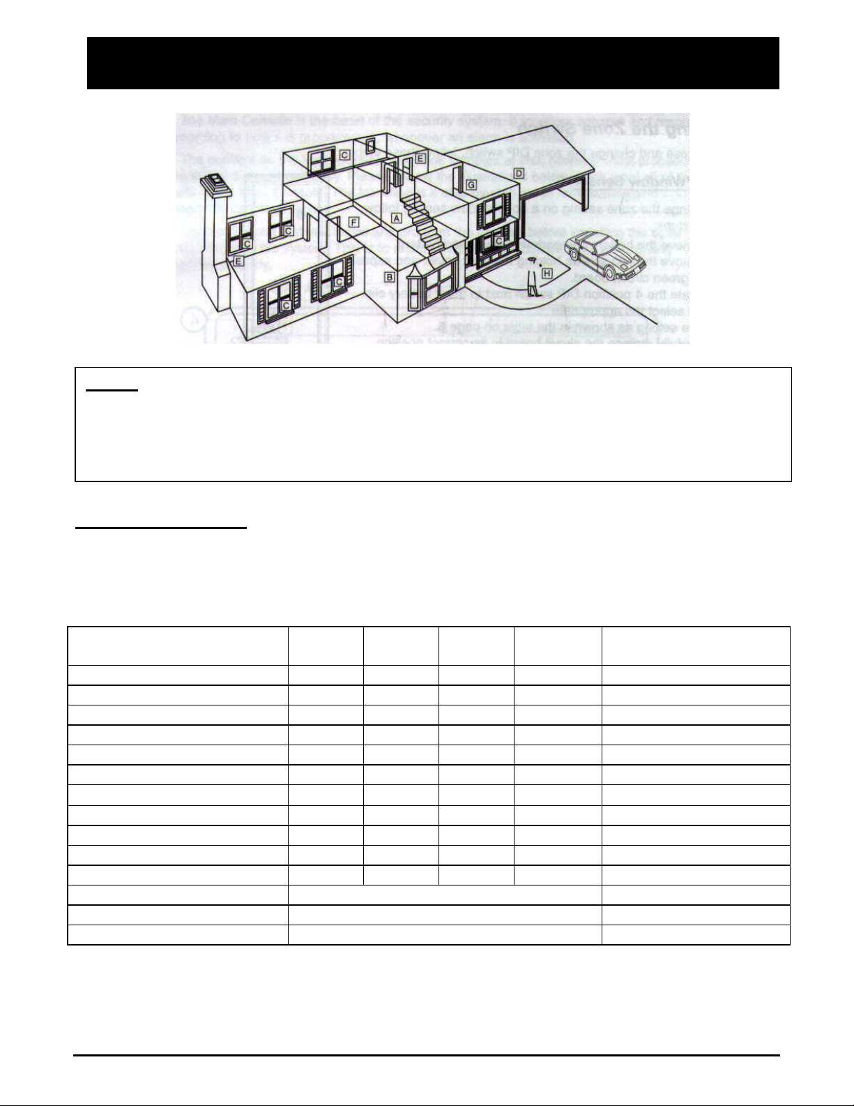
Setting the Alarm Zones……………………………………………..…8
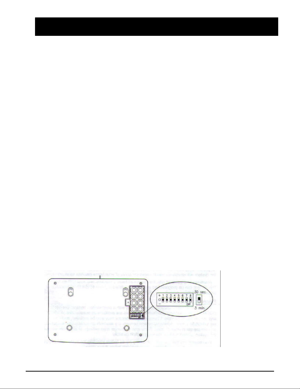
Setting the Zone Switch...……………………………………………..10
About the main console.……………………………………………………..11
Installing the Main Console...…………………………………………..12
About the Motion Sensor…………………………………………………...13
Installing the Motion Sensor…………………………………………...14
About the Door/Window Sensor………………………………………….…..15
Installing the Door/Window Sensor……………………………………...16
About the External Siren.…………………………………………………...17
Installing the External Siren.…………………………………………...17
About the Key Chain Remote…...…………………………………………….17
Operating the System.……………………………………………………..18
About Passwords……………………………………………………18
Arming the System using the Main Console…..………….…………….….19
Arming the System using the Key Chain remote Control……………………...19
Disarming the system using the Main Console………………………….….19
Disarming the System using theKey Chain remote Control…………………...20
Setting the Telephone Numbers for the Auto-dialer……………………….…20
Recording an Emergency Message.……………………………………..22
Changing Your Emergency Message…………………………………….23
Special Functions…………………………………………………...23
Maintenance…………………………………………………………….25
Troubleshooting…………………………………………………….25
Power requirements.………………………………………………………26
Optional Accessories……………………………………………………...26
Warranty.……………………………………………………………….27
2
Table of Contents

Congratulations on choosing the Home Sentinel® Home Security Alarm System. This alarm
system is high-quality, reliable and versatile. To ensure the best performance of your system,
please read this manual carefully and follow the precautions and instructions presented. Home
Sentinel® security systems are industry leaders in quality, service, and affordability.
About the Home Sentinel® Security Alarm System
The Home Sentinel® alarm security system continues the tradition of other Home Sentinel®
products. This alarm system is a complete security system that is designed to be simple and
easy to install and maintain. Some of the clear benefits of the alarm system include:
•Wireless, easy to use–No messy or expensive wiring is required to install the system
•Expandability –you can add different kinds of accessories to the system to create a more
complex system as your future needs may require
•Flexibility –you can choose the kinds of sensors and response action devices for the
system.
•Personalized –program the system to notify whoever you choose in case of alarm
activation
Out of the Box
Before proceeding, unpack your Home Security Alarm System and check that all of the
following components are present, and appear undamaged:
(1) Main Console Unit with mounting hardware
(1) Motion detector with battery and mounting hardware (if incl.)
(1) Magnetic Window/Door Detector with battery and mounting hardware
(1) Key Chain remote with battery ( if incl.)
(1) External Siren and 65 ft cable
(1) Backup Battery ( if incl.)
(1) Phone Cable
(1) AC Power Adapter
Note: Please remove the clear plastic overlay covering the LCD display, as it will be difficult
to see the display when a sensor is triggered 3
Introduction

The Home Sentinel® security system is designed to be as flexible as possible in order to
meet your present needs, and also to adapt as your needs change. For this reason, we
recommend that you read and consider the following information and plan your system
before installing devices
Choosing Locations
It is important to try and place the Main Console in an area central to the alarm sensors.
This way, all of the devices can transmit signals with maximum efficiency. The Main
Console must also be positioned near a power outlet and a telephone jack for the auto-
dialer. The aerial antenna on the main console should also be up for maximum reception to
the sensors
System ID Codes
A unique system ID code is used to avoid any interference caused by other radio frequency
sources, including neighbors using their own security systems. This allows the Main
Console to communicate clearly with other devices designed specifically for this system.
The 8 key, 3 level switch can be set to 6,000 possible combinations, ensuring a unique ID
code for your system.
Important –In order for the Main Console to pick up signals from other devices, such as a
door/window contact, motion sensor, detector, etc, you must have the same System ID
code as the main console.
Setting and Changing System ID Codes
All devices connected to the Main Console have a DIP switch panel with eight switches and
three levels each. The levels are marked as (+) (0) and (-). The factory default is ++++++++
(all in the up position).
4
Planning for Installation

To set or change the system ID code follow these steps:
1. Locate the DIP switch panel on the device. It is normally near the battery housing inside
the device. Remove the screw that is holding the battery cover.
2. Use a ball point pen, small screwdriver, or any fine object to move one or more switches.
3. Locate the DIP switch panels on other devices, including the Main Console and all
sensors. Make sure that all the codes are identical.
4. Once set, the Main Console is able to receive the correct frequency transmission from
each sensor.
Understanding Normal and Auto Modes
In the normal mode, the auto-dialer and external siren are disabled and only the internal siren on the
main console will sound when the system is triggered. This mode is used to “TEST” the communication
between the main console all the sensors.
Once the entire system has been installed and tested, the system should be kept in the AUTO mode at all
times, since this is the operating mode for the alarm system. Once the system is in the AUTO mode it
will activate the external siren and dial the preset telephone numbers when any sensor (s) is triggered
Setting the System to the Normal Mode
To set the system from Auto Mode to Normal Mode, follow these steps:
1. Enter your password
2. Press and hold the MODE (ALERT) key together with the AUTO (CLEAR) key
3. Release both keys
4. The LCD display will show NORMAL and blank off immediately
Setting the System to Auto Mode
To set the system from Normal Mode to Auto Mode, follow these steps:
1. Enter your password
2. Press and hold the MODE (ALERT) key together with the AUTO (CLEAR) key
3. Release both keys
4. The LCD display will show AUTO and blank off immediately
5

24 Hour and Home-Away Functions
The Home Sentinel® security system can work for you 24 hours a day, 7 days a week. It features a 24
hour status capability which is important for use with some accessory sensors. If a smoke alarm, or gas
detector are part of the system, those sensors can be kept active, even if the motion and contact sensors
are disarmed.
Home Status
The Home Status feature circumvents Zone 9/10/11, which is recommended for use when using your
motion sensors so that you and your family can move freely around your home without activating the
alarm, even when the system is armed. This means you have perimeter protection, where the entry
sensors, including magnetic contact sensors on doors and windows are active but the motion sensors are
inactive. ( THE SYSTEM SHOULD BE IN THE AUTO MODE )
To set the system to Home Status, follow these steps:
1. Make sure the system is not armed
2. Press and hold the MODE (ALERT) key together with the HOME (#1 ) key
3. Release both keys
4. The LCD display flashes ALERT
Away Status
When the system is on Away Status, all sensors are active and can trigger an alarm ( system must be in
the AUTO mode )
To set the system to Away Status, follow these steps:
1. Press and hold the MODE (ALERT) key
2. Press and hold the MODE (ALERT) key together with the HOME (#1 ) key
3. Release both keys
4. The LCD displays ALERT as steady
6
Operating the System

Setting the Alarm Period
Located at the back of the Main Console, inside the battery compartment and beside the 8 ID
dip switches is a separate switch which can be set at 30 seconds ( top) or 3 minutes ( bottom).
This switchsets the length of time that the siren will sound when the alarm is activated in the
AUTO mode. To change the alarm time, follow these steps:
1. Remove the battery cover from the back of the Main Console
2. Slide the alarm period switch to desired position (top position 30 sec, bottom
position 3 min ).
Alarm Delay Time
The Home Sentinel® security system provides two kinds of delay times.
1. The 60 second exit delay when you arm the system allows you to leave the premises
without activating the alarm or auto-dialer. This is the time between when the system is
activated, and when it becomes armed
2. The 30 second entry delay allows you to enter your premises and disarm the system
before it triggers an alarm. This entry delay time is applied to zones 6 –8,
recommended for the door sensors.
Both the entry and exit delay times are factory set and can not be changed. Once the delay has been
activated, you will hear a long beep. After the long beep the system becomes fully active
Installing the Back-up Battery ( if incl.)
While the battery cover on the bottom of the Main Console is removed to set the System ID
code and Alarm Period switches, the rechargeable Back-up Battery should be installed. To do
this;
1. Locate the plug inside the battery compartment of the Main Console, and connect the Back-
Up battery to this plug noting the correct polarity of the wires. ( 9.6 V battery pack )
2. Re-install the battery cover.
7

This back-up battery will supply an 8 hour emergency back-up if there was a power failure, and
will supply the memory required to save all programming.
Please note: If you forget your password, disconnect the back-
up battery from the main unit
as well as the AC adapter. Re-connect the back-up battery and re-plug unit. This
will default the password back to 1251.
Setting Alarm Zones
The Home Sentinel® security system lets you designate particular areas within your home for
protection by separate “zones” of the system. If zones are set and an alarm is triggered, the
system will identify the area or zone that has been activated
Alarm sensors installed with the system all have a four-key, two level DIP switch. The system
can be programmed with up to 14 different zones to identify the location of an activated alarm
sensor.
Planning for Zones
The Home Sentinel® security system comes with a door/window sensor, pre-
set to DOOR 1
zone. Additional door/window sensors are available as accessories ( model DT 4) and are
preset to WINDOW 1 zone. A motion sensor may also be included, and if so, is preset to
ROOM 1 zone. Additional motion sensors are available as accessories ( model MD 4) and are
Preset to ROOM 2 zone. If you wish to change zone settings, or add more sensors to the
system, please read the following section carefully.
We recommend that you plan for setting zones before installing the system. To evaluate your
need in setting or changing zone settings, follow these steps:
1. Use the sample illustration below to note the typical locations for different kinds of alarm
sensors.
2. Compare the illustration with you own home to determine where your sensors should be
installed and how your home can be sectioned into zones. (Any sensor installed should be
no more than 100 ft away from the main console )
3. Use the blank zone chart at the back of this manual to document the alarm sensors and
associated zones that you wish to set.
8

Zone Construction Chart
Use the following chart to help you understand and set zone areas. For example, Door 1 would have a
dip switch setting of 1 (up) for #1 switch, 0 (down) for #2 switch, 0 (down) for #3 switch and 1 (up) for
#4 switch. This chart has designated each alarm sensor as its own zone, however it is possible to use an
unlimited number of sensors, all set to operate within the same zone.
Switch Position
or Zone #1 #2 #3 #4 Zone No.
Window –1 ( Instantaneous ) 0 1 1 1 Zone 1
Window –2 ( Instantaneous ) 1 0 1 1 Zone 2
Window –3 ( Instantaneous ) 0 0 1 1 Zone 3
Window –4 ( Instantaneous ) 1 1 0 1 Zone 4
Window –5( Instantaneous ) 0 1 0 1 Zone 5
Door –1 (delay) 1 0 0 1 Zone 6
Door –2 (delay) 0 0 0 1 Zone 7
Door –3 (delay) 1 1 1 0 Zone 8
Room –1 ( Instantaneous ) 0 1 1 0 Zone 9
Room –2 ( Instantaneous ) 1 0 1 0 Zone 10
Room –3 ( Instantaneous ) 0 0 1 0 Zone 11
Gas –2 ( 24 hour mode) Preset in factory Zone 12
Smoke & Fire (24 hour mode) Preset in factory Zone 13
Gas –1 ( 24 hour mode ) Preset in Factory Zone 14
9
Planning for Installation
Legend
A –Main Console Unit E –Smoke Detector
B -Motion Sensor F -Gas/Propane Detector
C -Door/Window Sensor G -CO Detector
D -External Siren/Strobe Light H -Key Chain Remote Control

Setting the Zone Switch
To access and change the zone DIP switch, follow these steps:
Door/Window Sensor
To change the zone setting on a door/window sensor, follow these steps:
1. Remove the battery compartment cover and battery.
2. Remove the two screws holding the front cover, and expose the green circuit board.
3. Locate the
4 pin DIP switch next to the + battery clip, and select the appropriate zone setting as
shown in the table on page 9
4. Carefully replace the circuit board to its correct position.
5. Re-assemble the sensor covers and replace the battery
Anti-Tamper Switch
Please note: If the access cover is removed on the door/window contact transmitter, then the alarm will
sound ( provided the battery is installed ). This is an anti-tamper system, where as if the anti-tamper
switch ( illustration 1 ) is activated; by removing the cover, then the siren will sound
Motion Sensor
1. Remove the battery compartment cover and battery
2. Remove the two screws holding the front cover, and lift the cover away from the unit, exposing the
inside circuit. Be careful not to damage the wiring connected to the LED indicators.
3. Locate the 4 pin DIP switch ( located above the 8 pin System ID DIP switch), and select the
appropriate zone setting as shown in the table on page 9.
4. To the right of the 8 pin ID DIP switch is an OFF/ON/TEST switch:
10
Planning for Installation

OFF –Passive Infrared (PIR) is in the “OFF” status
ON -PIR is in the regular mode with a 2 minute idle time
TEST –PIR disables the 2 minute idle time, and works with a 5 –10 second interval
( Please note: Factory preset switch is in the “OFF” position
5. Carefully replace the circuit board to its correct position
6. Re-assemble the sensor covers and replace the battery
The Main Console is the heart of the security system. It monitors sensors and responds according to how
it is programmed, whenever an alarm is activated.
The controls on the Main Console may look complex at first, however most procedures are straight
forward and easy. Please review the illustrations below which label all of the parts of the Main Console.
The following is a step-by-step guide for installing and programming the console.
We recommend that you install and program the console before installing the other components of the
system. This is to ensure that all of the components are working together properly
11
About the Main Console

About the Ma
Installing the Main Console
Remember that the Main Console must have access to a power outlet and to a telephone jack. It also
performs better if it is in a position central to the alarm sensors.
Mounting the Console Main Console
The Main Console may be set on a tabletop, or mounted on a wall. To mount the console on a wall,
follow these steps:
1. Locate the four rubber pads on the back of the Main Console. Note that the two pads at the top of
console ( towards the antenna ) are removable
2. Remove the two top pads and store then away for future use.
3. Measure and fix screws into the wall so that the two screws fit into grooves left under the removed
pads.
4. Set the console onto the screws and carefully allow the console to drop into the grooves securely.
Powering the Main Console
Once you are satisfied with the System ID Code, Alarm Zones, and Alarm Period settings, power up the
Main Console by following these steps:
1. Locate the AC adapter
2. Attach the narrow end of the adapter into the connector provided at the back edge of the console, to
the left of the antenna.
3. Plug the other end of the adapter into an electrical outlet
4. Watch as the LCD screen and the Armed light become active for five seconds and then return to
blank/off
12
LEGEND
1 –REC BUTTON 8 -FIRE BUTTON 15 –TEL.LINE JACK
2 -PLAY BUTTON 9 -BURGLARY BUTTON 16 -SPEAKER
3 -SET BUTTON 10 -ALERT/MODE BUTTON 17 –ARMED LED IND.
4 -CLEAR/AUTO BUTTON 11 -PANIC KEY 18 -MICROPHONE
5 -ENTER/ARM BUTTON 12 -LOW BAT.INDICATOR 19 -ANTENNA
6 -NUMERIC KEYPAD 13 -AUX.OUTPUT TERMINAL JACKS 20 -DC POWER JACK
7 -MEDICAL EMERGENCY BUTTON 14 -TELEPHONE JACKS 21 -LCD PANEL
22 -TEST LED
23 -MUTE BUTTON
24 -TEST BUTTON
About the Main Console

About the Main Console
Connecting the Telephone LineCConnecting the Telephone
To connect the Main Console to the telephone line, follow these steps:
1. Locate the two phone jacks on the back edge of the console. These phone jacks are side by side and
are marked “ Phone” and “Line”.
2. Connect one end of the telephone cord that came with the system into the connector labeled Line.
3. Connect the other end of that cord into the wall jack.
4. Connect a telephone to the Main Console through the second jack.
NOTE: It is more useful to “swap” cords with your existing telephone. This may be desirable if you
need a longer cord for one connection or another.
Setting the Antenna
Carefully extend the antenna upward in order to maximize the range of communication between alarm
sensors and the Main Console.
About the Motion Sensor ( if incl.)
The Motion Sensor is designed to protect rooms and hallways by detecting the movement within its
range. The effective range of the motion sensor is 35 feet long, and with an 84 degree horizontal angle.
The motion sensor can sense infrared heat sources, like the human body. When the sensor detects the
movement of a heat source traveling within its range, it transmits a signal to the Main Console. When
the sensor is triggered, an orange light will glow momentarily on the front of the sensor. The status of
the motion sensor appears in the Room area, if adjusted to Room 1~ 3 of the LCD display on the Main
Console.
The sensor has a two-minute idle time after each detection when it will not transmit again. This
conserves battery power. After two minutes, it resumes activity and can trigger an alarm again.
13
About the Motion Sensor

Notes on the Motion Sensor
Motion sensors detect the movement of humans and animals within their range. In order to prevent false
alarms we recommend that you do not install any motion sensor in the following areas:
•Where there is a device that causes a rapid temperature change, or rapid heat transfer, for instance,
near an air conditioner, fire place, heater, or any other intermittent heat sources.
•Where the sensor will be exposed to direct sunlight
•Near large electrical devices and/or high output radio frequency sources, like refrigerators,
microwaves, computers, and light dimmers
•Where the effective range of the sensor is covered or blocked by furniture
•Where pets enter and exit freely, for instance a cat or dog door.
•Directly opposite any large object with substantial reflecting properties, like large windows or
mirrors.
•In a bathroom or other area that is exposed to moisture and extreme temperature change.
Installing the Motion Sensor
Before installing the sensor, consider the following points:
•Mount the sensor at two meters (6 ½ feet ) high for best coverage
•Mount the sensor with a 14 degree downward incline against the wall for optimum range
To install the Motion Sensor, follow these steps:
1. Locate and install the mounting bracket. The mounting bracket comes in two parts. Firmly press the
ball portion into the socket until it snaps securely
14

2. Measure and drill as necessary, then apply the two wall anchors and screws included with the system
to secure the bracket to the wall at 6 ½ feet above the floor.
3. Position the sensor for optimum range
4. Test the sensor by walking within its range. When the sensor is triggered, the TX LED light will flash
once.
About the Door/Window Sensor
The magnetic Door/Window sensor is a contact sensor that can be used on any door or window that
opens. When a sensor is active and the magnetic contact is broken by opening the door or window, an
alarm is triggered. The status of the sensors can be read from the door or Window area of the Main
Console’s LCD display.
If one or two sensors are included with your system they are pre-programmed to activate on DOOR 1
and DOOR 2 zones. Refer to the labels attached for identification.
15
About the Door/Window Sensor
Note: Double sided adhesive is included in the package for your convenience. If you are installing
the sensor in an area where it may be more convenient for you, secure the sensor using the
adhesive.
Notes on the battery: When the battery voltage is too low for normal operation the BATT LED
Light will glow on the Motion Sensor, and the ROOM area on the Main console LCD displaywill
blink. The Main Console will also emit two short beeps. When this happens, replace the battery
immediately and press the clear button to reset the system.

Notes on the Door/Window Sensors
•The LED on the sensor will flash once when the sensor is triggered
•There can not be a gap greater than ¼ inch ( 5 mm) between the magnet sensor and the magnet, or
the sensor will not work properly
•As discussed in the earlier section : Setting the Zone Switch –( Door/Window sensor ), there is also
an ant-tamper switch installed near the 8 ID dip switches. If the access cover is removed or tampered
with, then the siren will sound immediately ( as long as the battery is installed )
Installing a Door/WindowSensor
To install a Door/Window Sensor, follow these steps:
1. Remove the magnet from the packaging and note that the double sided adhesive tape is already
secured.
2. Remove the sensor from the packaging along with the included piece of double sided adhesive
tape. Apply tape to the back of the sensor
3. Find the arrow embossed on the sensor, just below the LED light. Find a similar arrow on the
magnet.
4. Before exposing the adhesive backing, align the two arrows on the surface where you want them
installed. Check that both parts of the device fit and that they can be mounted with a gap less than ¼”
between them.
5. Be sure that the surface area where the sensor and magnet will be fixed is clean and dry.
6. Remove the protective backing to expose the adhesive tape. Firmly apply the sensor and magnet to
the surface.
7. To test the sensor, open the door or window and watch as the LED indicator flashes once to indicate
that a signal has been transmitted
16
About the Door/Window Sensor

Please note: If the batteries are low on any sensor, the sensor ID will flash on the LCD display ( e.g.
Room 1, Door 2, Window 5, etc ). When this occurs, open the battery compartment on the sensor and
replace the battery. Come back to the main console and press the CLEAR (Auto ) key to erase the ID on
the LCD display.
The Home Sentinel® security system includes an external siren. The siren is an important deterrent to
intruders. Choose a location inside your home where the siren will not be plainly visible but can be
heard throughout the house. Also try to install the siren where the cable can be hidden, for example
along a baseboard.
When the siren is installed and the system is set to AUTO mode, it will emit a piercing 120 decibel siren
when any sensor is triggered
Installing the External Siren
1. Unpack the external siren and cable
2. Measure and drill as necessary, then apply anchors and screws included with the system to secure the
siren to a smooth flat surface.
3. Run the cable from the siren to the main console and plug the connector into either of the jacks
labeled OUTPUT
4. Conceal the cable from plain sight as much as possible.
The siren is active only when the system is in the AUTO mode. When the system is armed, the siren will
sound one short chirp. When the system is disarmed, the siren will sound two short chirps.
Note: The siren will activate regardless of the status on the main console ( ie.
Armed/disarmed/Auto/Normal/Home/Away ) when the 24 hour sensor/panic function or tamper switch is
activated.
The Key Chain Remote is a convenient way to arm and disarm the system. It also has a Panic Key
feature.
Arming with the Key Chain Remote
1. Press the Arm key
2. The Arm LED light on the Main Console panel lights and the LCD panel displays ALERT
17
About the External Siren
About the Key Chain Remote ( if incl.)

Disarming with the Key Chain Remote
1. Press the Disarm key
2. The ARM LED light on the Main Console switches off and the ALERT display disappears
Using the Panic Key
Press the panic key to activate the alarm and automatic dialer immediately. The auto-dialer will operate
even if the system is disarmed
About Passwords
A personal security password is programmed into the Main Console. You must enter the password in
order to change the memory data, such as a pre-set telephone numbers, or to disarm the alarm system
from the Main Console
The password is made up of four digits, and none may be “0”, only numbers between 1 and 9 may be
used. The factory sets a default password of 1251 for your system. If you forget your password unplug
the AC adapter from the wall outlet and disconnect the back-up battery ( if installed ). This will erase the
memory and default the password to 1251
Setting a Password
To replace the factory default password with your own personal four-digit code, follow these steps:
1. Think of your new four-digit code and keep it in mind. It is recommended that you select a number
which is easy to remember, perhaps relating to important dates such as a birthday or anniversary
2. Using the numeric keypad, enter the default password of 1251
3. Press and hold the Panic Key together with the Enter key and release together
4. Enter the new four digit code ( remember that zeros are not allowed )
5. A long beep will sound, indicating that the new password has been accepted.
18
Operating the System

Changing a Password
To change a password follow these steps:
1. Think of your new four-digit code and keep it in mind. It is recommended that you select a number
which is easy to remember, perhaps relating to important dates such as a birthday or anniversary.
2. Using the numeric keypad, enter the current password
3. Press and hold the Panic Key together with the Enter key and release together
4. Enter a new four digit code ( remember that zeros are not allowed ).
5. A long beep will sound, indicating that the new password has been accepted.
Arming the System using the Main Console
To arm the system from the Main Console, follow these steps:
1. Press the ALERT and ENTER keys at the same time, and then release it.
2. The ARM LED lights on the main console and the LCD panel displays ALERT
3. The External Siren will emit one short chirp followed by a 60 second exit delay before it becomes
fully armed.
Arming the System using the Key Chain Remote ( if incl.)
To arm the system using the Key Chain Remote, follow these steps:
1. Press the ARM button. The red LED will flash, indicating that the signal is sent to the Main Console.
2. The ARM LED on the Main Console lights and the LCD panel displays ALERT
3. The external siren will emit one short chirp to indicate that the system has been armed.
Disarming the System using the Main Console
To disarm the system from the Main Console, follow these steps:
1. Using the numeric keypad, enter your security password
2. The ARM LED light extinguishes and the ALERT on the LCD panel disappears
3. The siren will emit two short chirps to indicate that the system has been disarmed
19
Operating the System
This manual suits for next models
3
Table of contents
Other Home Sentinel Security System manuals
Popular Security System manuals by other brands

Leopard
Leopard LI-HDSDI-1080-D user manual

ProLogic
ProLogic C Series user manual

Electronics Line
Electronics Line infinite prime user manual

Lorex
Lorex VANTAGE LH110 ECO SERIES Product information

Kodak
Kodak Hawkeye - Brownie Hawkeye Flash Technical data

Interlogix
Interlogix Learn Mode Water Resistant Pendant Panic... installation instructions