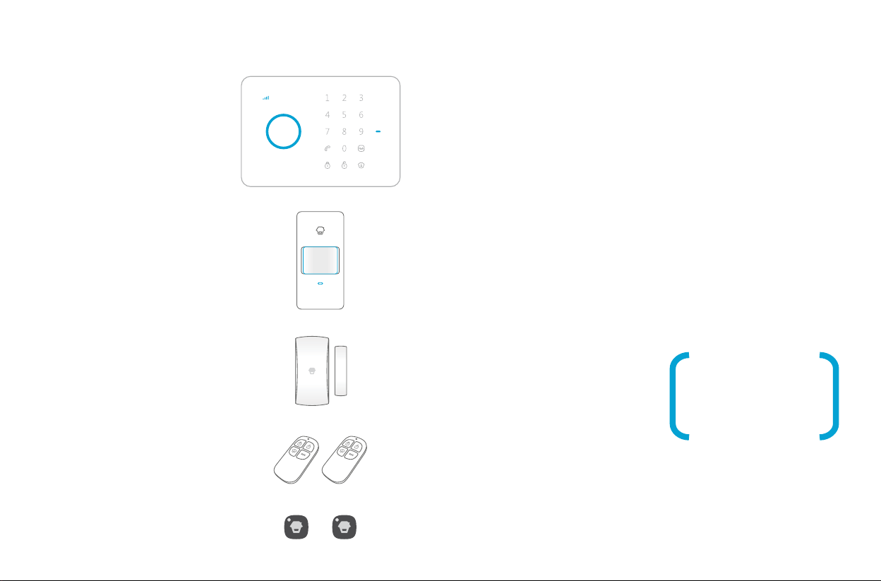
GSM - SMS - RFID - TOUCH
Wireless Security Alarm System
HD-G005 is a domestic security system with GSM dialer that provides
the following protection functions:
• INTRUDER ALARM using motion or perimetric sensors
• REMOTE HELP using remote control’s panic button
• DOMESTIC SECURITY using Gas, Smoke or Water detectors
• REMOTE MONITORING using telephone
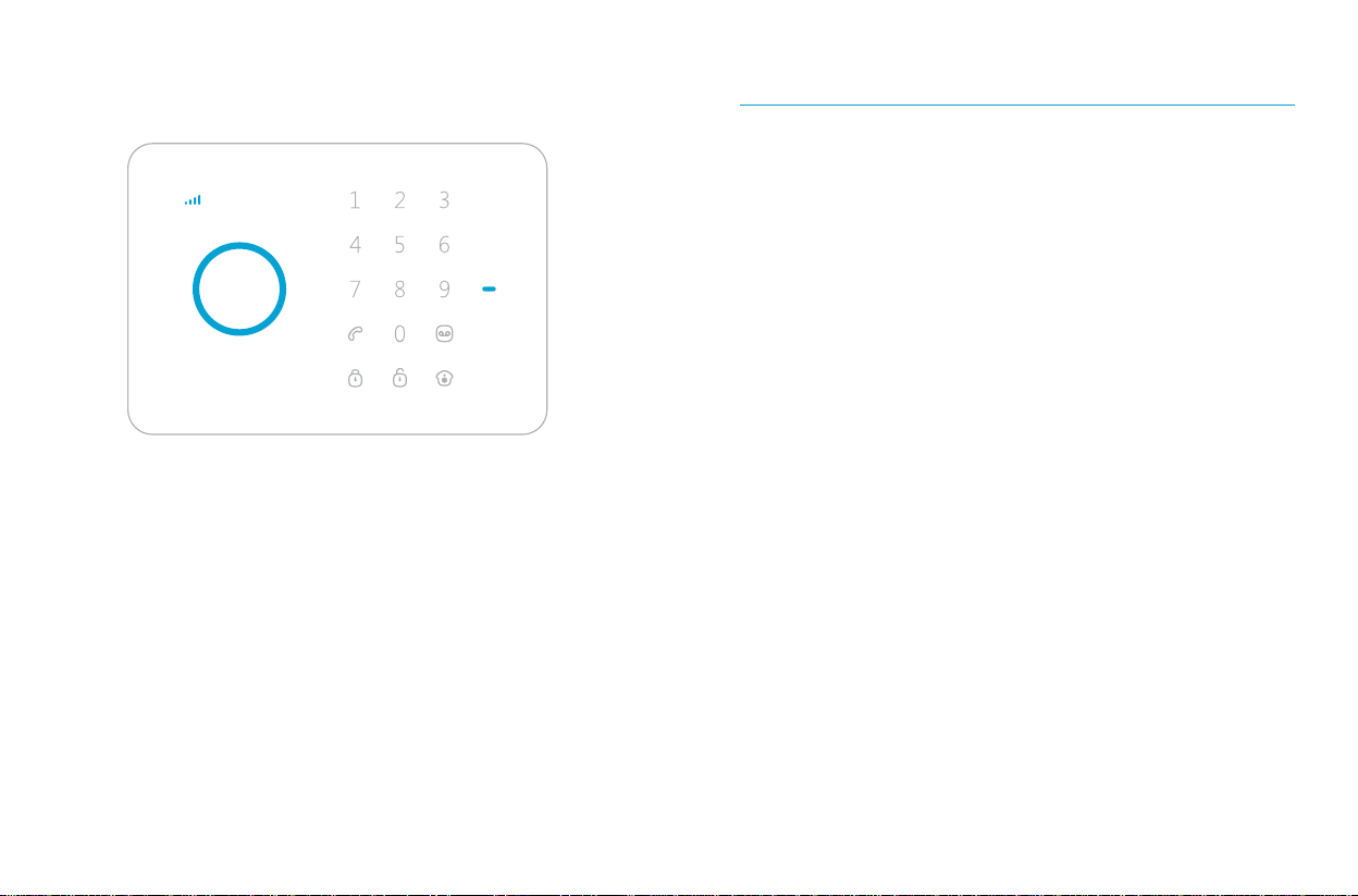
The system is configured and managed from the control panel by sending
SMS and with telephone calls.
Any change of status is notified to the numbers in memory by SMS.
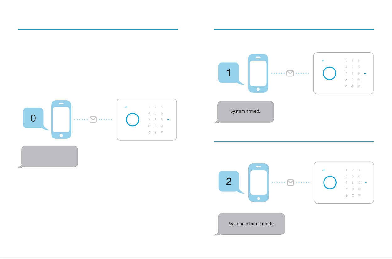
INTRUDER ALARM function can be programmed in 3 different ways:
1) Normal Mode (total protection): all sensors are armed.
2) Home Mode (partial protection): the perimetric sensors are armed
while the motion sensors, previously programmed in Home Mode,
are disarmed.
3) Delay Mode (total cover): the detectors programmed in this way
allow a time delay to enable the protected rooms to be entered and
exited without setting off the alarm.
REMOTE SUPPORT function can be armed in emergency situations by
means of the SOS panic button on the remote controls.
The siren will sound, SMS and phone calls will be made as
programmed.
DOMESTIC SECURITY function can be armed by configuring the
smoke, water and gas detectors and arming perimetric sensors
installed in zones not subject to access (H24 Mode: it always arms
regardless of the system status).
REMOTE MONITORING is activated on every intrusion or by sending
an SMS to the control panel that will call back immediately thus
opening a hands free communication channel with the home or
office where installed.
Particularly useful for communicating to people with restricted move-
ment and to help them as needed.
The system can also be disarmed using RFID devices like “Cards” or
“Tags”.
The system support up to 50 RFID devices of which 4 can be personal-
ized with user names.
Whenever any RFID device is used an SMS notification message will
be sent to the previously registered number.
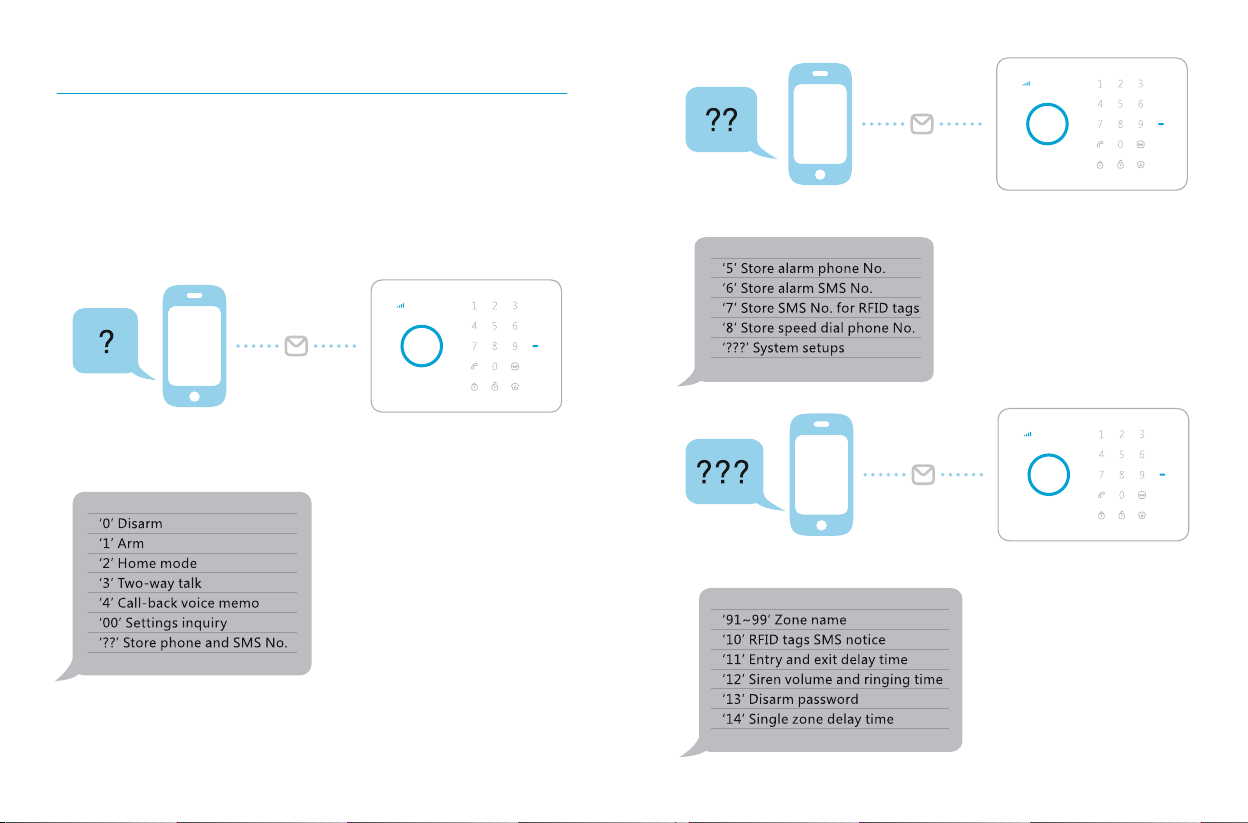
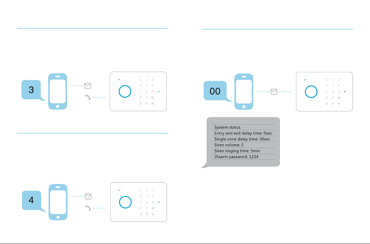
Operations
1 2