HOMEDEPOT 592-082 User manual

HOM(
DECORATORS
COLLECTION
Exterior Wall Lantern with Motion Sensor
SKU 592-082 (UPC 046335974449)
<2:6.8
(Aged Iron Finish)
INSTRUCTION MANUAL
Page 1
HB7251MA-292 E/S

Thank you for purchasing this Home Decorators Collection exterior light fixture.
This product has been manufactured with the highest standards of safety and
quality.
FEATURES:
1.MOTION SENSOR FUNCTION – At dusk the motion sensor will activate and
automatically turn the light on when moving heat sources (such as people and
vehicles) are detected within its coverage area. The motion sensor will remain
active throughout the night and deactivate at dawn.
2.SIX HOUR TIMER FUNCTION – At dusk the light will automatically turn on.
After five to six hours the light will turn off and the motion detector will activate.
The motion sensor will remain active throughout the night and deactivate at dawn.
3.MANUAL OVERRIDE – The user may manually turn on the light from inside
his home using a wall switch.
4.Uses medium-based incandescent or CFL light bulbs.
SPECIFICATIONS:
•Motion Sensor Range: Up to 30 ft (Varies with surrounding
temperature)
•Sensor Detection Angle: 220
•Electrical Requirements: 120 VAC, 60 Hz
•Maximum Load: 100 W Incandescent or 26 W Compact
Fluorescent
QUESTIONS, PROBLEMS, MISSING PARTS:
Before returning to your local Home Depot, please call our Customer Service
Team at 1-800-986-3460 orvisit www.homedepot.com/homedecorators.
Please reference your SKU(592082 Aged Iron Finish
fixture) or UPC (046335974449).
Page 2

CAUTION:
1.Before starting installation of this fixture or removal of a previous
fixture, disconnect the power by turning off the circuit breaker or by
removing the fuse at the fuse box.
2.CONSTULT A QUALIFIED ELECTRICIAN IF YOU HAVE ANY
ELECTRICAL QUESTIONS.
3.If you have any non-electrical questions about this fixture, please
contact our Customer Service Team at 1-800-986-3460 or visit
www.homedepot.com/homedecorators. Please reference your SKU
(592082 Aged Iron Finish fixture) or UPC
(046335974449).
4.Keep your receipt and these Instructions for Proof of Purchase.
TOOLS REQUIRED FOR ASSEMBLY & INSTALLATION
(not included):
Page 3
Exterior Silicon
Rubber Sealant
Wire
Strippers
Wire Cutters
Safety Glasses Electrical Tape
Phillips Screwdriver Flathead Screwdriver
Light Bulb (100 W Max.
or CFL equivalent)

PARTS INCLUDED (parts are not to scale):
Page 4
(1) Mounting Bracket
(2) Hex Nuts
(3) Wire Nuts
(2) Bracket
Mounting Screws
(2) Fixture
Mounting Screws
(1) Main Fixture Body
(2) Hood Screws
(2) Lock Nuts

CAUTION:
1.Before starting installation of this fixture or removal of a previous fixture,
disconnect the power by turning off the circuit breaker or by removing the fuse at
the fuse box.
2.All electrical connections must be in accordance with local and National
Electrical Code (N.E.C.) standards. If you are unfamiliar with proper electrical
wiring connections obtain services of a qualified electrician.
3.There are no serviceable parts inside the motion sensor. DO NOT try to repair
or disassemble the unit. Doing so could damage the unit and cause possible
electrical shock. Consult a qualified electrician if needed.
SELECTING A LOCATION:
1.When selecting a location, be aware of the motion sensor’s maximum range of
30 ft and 220º detection angle (Fig. 1). In addition, be aware of its 15º detection
down-angle (from horizontal) (Fig. 2). Mounting the fixture too high or in front
of a sloped surface, such as an uphill walkway or driveway, may affect the
motion sensor’s effectiveness.
2.Select locations away from heat sources, such as heating vents, air conditioners,
and heated swimming pools.
220
e
Fig. 1
15
e
Fig. 2
Page 5

Fig. 3
SENSOR
Least Sensitivity
SENSOR
Best Sensitivity
Page 6

Page 7
INSTALATION & ASSEMBLY:
1.Carefully unpack the fixture. Lay out all parts on a clean surface.
2.Thread the Fixture Mounting Screws (#6) into the provided holes of the
Mounting Bracket (#7) as shown. Thread the Hex Nuts (#9) onto the Fixture
Mounting Screws (#6), as shown. Do not tighten the Hex Nuts (#9) at this time
(Fig. 4).
3.Pull the power supply wires out from the Outlet Box (#4), and mount the
Mounting Bracket (#7) to the Outlet Box (#4), using the Bracket Mounting
Screws (#8) (Fig. 4).
4.Attach the Black Supply Wire (#5) to the Black Fixture Wire (#12) and the
White Supply Wire (#16) to the White Fixture Wire (#13) using Wire Nuts (#14).
Connect the Fixture Ground Wire (#11) and the Supply Ground Wire (#15)
together using a Wire Nut (#14). Wrap all wire connections with electrical tape
for a more secure connection (Fig. 4).Note: If you have electrical questions,
consult your local electrical code for approved grounding methods.
10. Wall
Plate
3. Lock
Nut
13. White
Fixture Wire
11. Fixture
Ground Wire
14. Wire
Nut
5. Black
Supply
Wire
4. Outlet
Box
7. Mounting
Bracket
8. Bracket
Mounting
Screw
9. Hex
Nut
6. Fixture
Mounting
Screw
16. White
Supply Wire
15. Supply
Ground Wire
12. Black
Fixture Wire
Fig. 4

Page 8
INSTALLATION & ASSEMBLY (CONTINUED):
5. Place the Wall Plate (#10) over the Outlet Box (#4) and onto the Fixture
Mounting Screws (#6), and adjust the Fixture Mounting Screws (#6) until
they protrude out from the Wall Plate (#10) 1/4". Remove the Wall Plate
(#10) and secure the position of the Fixture Mounting Screws (#6) by
tightening the Hex Nuts (#9) against the Mounting Bracket (#7). Place the
Wall Plate (#10) back onto the Fixture Mounting Screws (#6), and secure it
into place using the Lock Nuts (#3) provided.
6. After installing the fixture, caulk the
upper 2/3s of the Wall Plate (#10) to
mounting surface. Leave the bottom 1/3
un-caulked for drainage of any water that
might leak drainage of any water that
might leak into the enclosure. The
manufacturer recommends a non-drying
exterior caulking material. A good
example is a clear silicone rubber sealant
for exterior use.
7. Install up to a 100 watt incandescent
Light Bulb in the socket of the Main
Fixture Body. Do not exceed a 100 watt
incandescent light bulb or 26 watt SBCFL
(Fig. 5).
8. Installation is complete. Turn on power at
the circuit breaker or fuse box. Turn the
light switch on to activate the fixture.
Fig. 5

OPERATION:
GETTING STARTED: After installing the fixture, slide the “TIMER” switch
to “TEST”. Restore power at the circuit breaker and turn on your wall
switch (if applicable). The light will turn on and remain on for
approximately 5 seconds. Then the light will flash 3 times and then turn off.
(If the “TIMER” switch is set to “6 HOUR” and it is night, the light will stay
on continuously until you switch to “TEST”.)
In the beginning, it is necessary to first switch to TEST mode, which will allow
you to easily set the motion sensor sensitivity. In TEST mode, the motion
sensor will turn on the light when it senses movement. Four to five seconds after
movement has stopped, the light will turn off.
SETTING SENSITIVITY IN TEST MODE: NOTE: Sensitivity directly
correlates to the sensor’s detection range. In TEST mode, slide the
“SENSITIVITY” switch to a desired level: “L” for low, “M” for medium, or
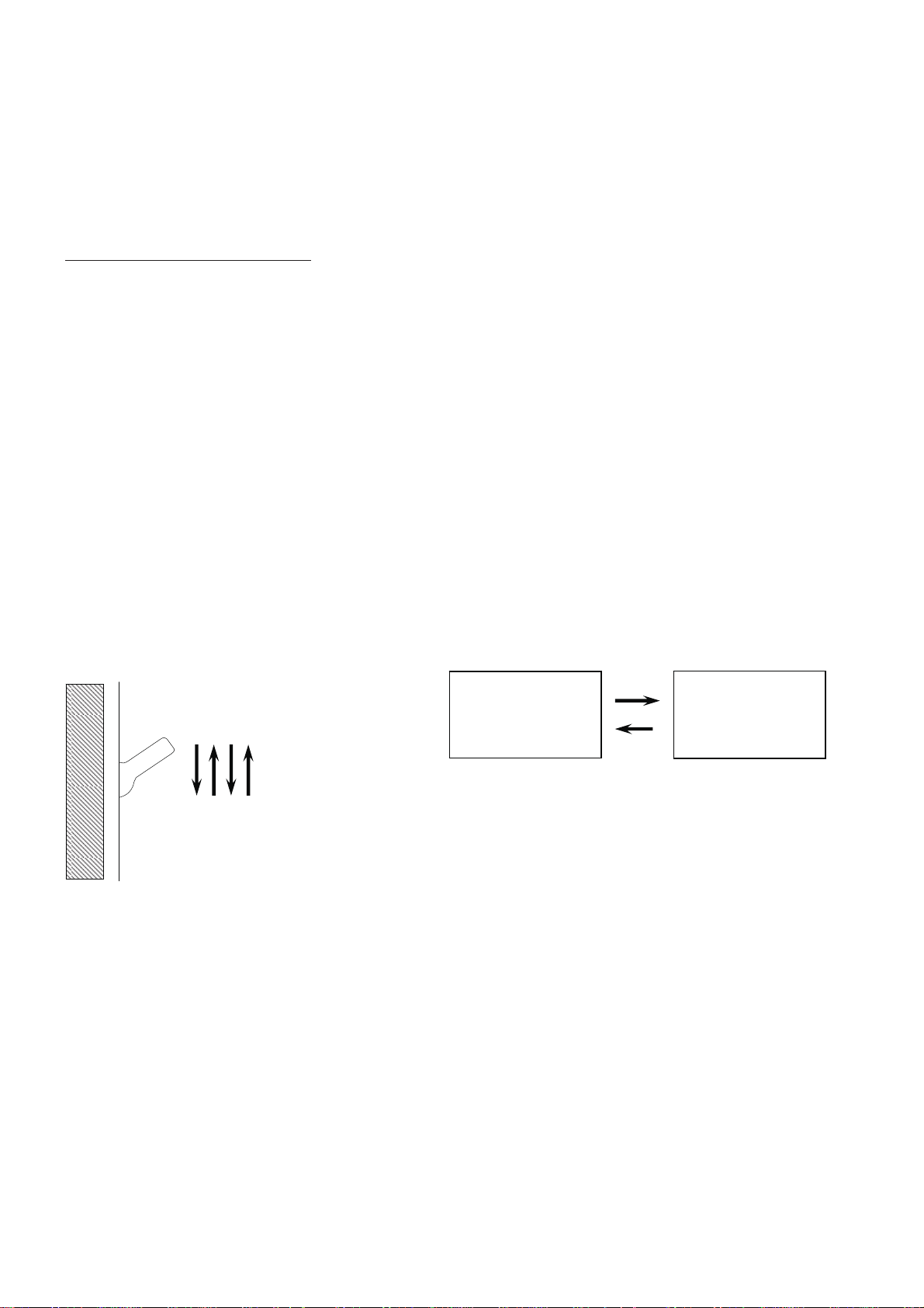
“H” for high. From a distance, walk through the coverage area. When the
light turns on, note your distance from the fixture. Try different
approaches toward the fixture from various angles. Especially, try pathways
where you expect high traffic, such as walkways and driveways.
If necessary, select a different “SENSITIVITY” switch position to increase or
decrease sensitivity/range. Repeat the steps above. Continue to adjust the
sensitivity until optimum results are attained.
SELECTING FUNCTION:After setting the sensitivity, select the function by
sliding to “TIMER” switch to one of the following positions:
“TIMER”
Switch Position Function Description
4Motion
Sensor
At dusk, the motion sensor will activate (Motion Sensing Mode). Any movement within the
coverage area, will cause the light to turn on. After movement has stopped, the light will
remain on for the preset time limit (4 or 10 minutes). At the time limit, the light will turn off.
The motion sensor will remain active throughout the night. At dawn, the motion sensor will
deactivate.
10
6 HOUR Six Hour
Timer
At dusk, the light will turn on and remain on for 5 to 6 hours. At this time, the light will turn
off and the motion sensor will activate (Motion Sensing Mode). Any movement within the
coverage area, will cause the light to turn on and remain on for 10 minutes. At 10 minutes,
the light will turn off. The motion sensor will remain active throughout the night. At dawn,
the motion sensor will deactivate.
Page 9

OPERATION (CONTINUED):
NOTE: To make sure the above functions operate properly, always keep the wall
switch in the “ON” position (include the daytime).
MANUAL OVERRIDE:You may manually turn on the light from inside your
home using the wall switch that controls your light fixture. This feature may
be used during nighttime when the light is off, while the circuit is in the
Motion Sensing Mode. To manually turn on the light and activate the Manual
Override, quickly flip your wall switch OFF-ON-OFF-ON within a 3 second
span. (Fig. 6) The light will remain on until the override is deactivated.
To turn off the light and deactivate the Manual Override, flip your wall switch
OFF-ON-OFF-ON again (Fig. 6). This will return the circuit back to the
Motion Sensing Mode. If you do not deactivate the Manual Override, the
light will remain for 8 hours or until dawn (which ever comes first), at which
time the light will turn off automatically. You may toggle the switch in this
manner as many times as you need, to alternate between the two modes,
Manual Override Mode (light on) and Motion Sensing Mode (light off) (Fig. 7).
Motion
Sensing Mode
(light off)
Manual
Override Mode
(light on)
NOTE: This switch toggling sequence
alternates the circuit between Manual Override
(light on) Mode and Motion Sensing Mode
(light off) Fig. 7
Fig. 6
Flip wall switch
OFF-ON-OFF-ON
within 3 seconds
Switch in the
“ON” position
Page 10

SYMPTOM POSSIBLE CAUSE SOLUTION
In motion sensing mode, the light
does not turn on when there is motion.
Wall switch or circuit breaker is off. Turn on a switch or
circuit breaker.
Light bulb may be dead. Test the light bulb in a
known working light fixture.
Light bulb is loose. Tighten the light
bulb in the socket.
Incorrect or loose wire connections. Check wire connections.
Too much sunlight is shining into
photocell sensor in the early evening. Relocate fixture away from
a western facing wall.
Too much light is shining onto
photocell sensor due to another light
source, such as a street lamp or other
light fixture.
Eliminate or turn off other light
source, block other light source
from shining onto photocell
sensor, or relocate fixture.
Moving persons or vehicles are below
the view of the motion sensor,
because motion sensor is mounted too
high.
Relocate fixtrue to a lower
position or to a different
location. See Fig. 2.
In motion sensing mode, the light
stays on continuously.
False triggering caused by a heat
source, such as a heater or dryer vent,
or heated swimming pool.
Eliminate heat source
or relocate fixture.
The light comes on for no apparent
reason
Street or sidewalk traffic is triggering
motion sensor Lower the sensitivity.
False triggering caused by a heat
source, such as a heater or dryer vent,
or heated swimming pool.
Eliminate heat source
or relocate fixture.
The light comes on during the
daytime or too early in the evening.
The fixture may be installed in a
shadded area, such as under a porch or
eave, preventing daylight from
shining onto the photocell sensor.
Relocate the fixture.
In the six-hour timer function, the
light comes on too late in the evening. Too much sunlight is shining onto the
photocell sensor in the early evening. Relocate fixture away from
a western facing wall.
In the six-hour timer function, the
light does not come on at night.
Too much light is shining onto
photocell sensor due to another light
source, such as a street lamp or other
light fixture. Cover the photocell
sensor with black electrical tape to
verify the light will turn on when
there is sufficient darkness.
Eliminate or turn off other light
source, block other light source
from shining onto photocell
sensor, or relocate fixture.
TROUBLESHOOTING:
Page 11

Page 12
PRODUCT MAINTENANCE:
1.Disconnect power to the fixture by turning off the circuit breaker before any
maintenance.
2.To clean the outside of the fixture, use a dry or slightly dampened clean cloth
(use clean water, never a solvent) to wipe the glass and surface of the fixture.
3.To clean the inside of the fixture, first disconnect power to the fixture by
turning off the circuit breaker or by removing the fuse at the fuse box. Next, use a
dry or slightly dampened clean cloth (use clean water, never a solvent) to wipe
the inside glass and interior surface of the fixture.
4.Do not use any cleaners with chemicals, solvents or harsh abrasives. Use only a
dry soft cloth to dust or wipe carefully.
DISCLAIMER:
NOTE: This equipment has been tested and found to comply with the limits for a
Class B digital device, pursuant to Part 15 of the FCC Rules. These limits are
designed to provide reasonable protection against harmful interference in a
residential installation. This equipment generates, uses and can radiate radio
frequency energy and, if not installed and used in accordance with the
instructions, may cause harmful interference to radio communications. However,
there is no guarantee that interference will not occur in a particular installation.
If this equipment does cause harmful interference to radio or
television reception, which can be determined by turning the equipment off and
on, the user is encouraged to try to correct the interference by one or more of the
following measures:
•Reorient or relocate the receiver antenna.
•Increase the separation between the equipment and receiver.
•Install the product onto on a circuit different from that to which the receiver is
connected.
•Consult with the dealer or an experienced radio/TV technician for help.
CAUTION: Any changes made to the electronics circuit will void this
equipment’s compliance with Part 15 of the FCC Rules and should not be
operated.

LIMITED WARRANTY
The manufacturer warrants this lighting fixture to be free from defects in
materials and workmanship for a period of three (3) years from date of purchase.
This warranty applies only to the original consumer purchaser and only to
products used in normal use and service. If this product is found to be defective,
the manufacturer’s only obligation, and your exclusive remedy, is the repair or
replacement for the product at the manufacturer’s discretion, provided that the
product ahs not been damaged through misuse, abuse, accident, modifications,
alterations, neglect, or mishandling. This warranty shall not apply to any product
that is found to have been improperly installed, set-up, or used in any way not in
accordance with the instructions supplied with the product. This warranty shall
not apply to a failure of the product as a result of an accident, misuse, abuse,
negligence, alteration, or faulty installation, or any other failure not relating to
faculty material or workmanship. This warranty shall not apply to the finish on
any portion of the product, such as surface and/or weathering, as this is
considered normal wear and tear.
The manufacturer does not warrant and specially disclaims any warranty,
whether express or implied of fitness for a particular purpose, other than
the warranty contained herein. The manufacture specifically disclaims
any liability and shall not be liable for any consequential or incidental
loss or damage, including but not limited to any
labor/expense cost involved in the replacement or repair of said product.
Page 13

Linterna de Pared para Exterior
Con Sensor de Movimiento
SKU 592-082 (UPC 046335974449)
<2:6.8
(Acabado de Hierro Envejecido)
HOM(
DECORATORS
COLLECTION
MANUAL DE INSTRUCCIONES
Page 14
HB7251MA-292 E/S

Gracias por la compra de este luminario exterior de Home Decorators Collection.
Este producto ha sido fabricado con los más altos niveles de seguridad y calidad.
CARACTERÍSTICAS:
1. FUNCIÓN DEL SENSOR DE MOVIMIENTO – Al anochecer en sensor de
movimiento se activará y automáticamente encenderá la luz cuando se detecten
fuentes de calor (como personas o vehículos) dentro de su área de cobertura. El
sensor de movimiento permanecerá activo durante la noche y se desactivará al
amanecer.
2. FUNCIÓN DE CRONÓMETRO DE SEIS HORAS – Al anochecer la luz se
encenderá de manera automática. Después de cinco o seis horas, la luz se
apagará y el sensor de movimiento se activará. El sensor de movimiento
permanecerá activo durante la noche y se desactivará al amanecer.
3. ENCENDIDO/APAGADO MANUAL – El usuario puede encender la luz de
manera manual desde su hogar con un interruptor de pared.
4. Utiliza focos de base mediana CFL o incandescentes.
ESPECIFICACIONES:
•Rango del sensor de movimiento: Hasta 30 pies (varía con la
temperatura circundante)
•Ángulo de detección del sensor de movimiento: 220e
•Requerimientos eléctricos: 120 VAC, 60 Hz
•Carga máxima: 100 W Incandescente o 26 W
Fluorescente compacto
PRGUNTAS, PROBLEMAS, PIEZAS FALTANTES:
Antes de regresar a su tienda local deHome Depot, llame a nuestro Servicio al
Cliente al 1-800-986-3460 o visite www.homedepot.com/homedecorators.
Por favor, referir a SKU(592082 Lámpara con Acabado de
Hierro Envejecido) o UPC (046335974449).
Page 15

PRECAUTIÓN:
1.Antes de comenzar la instalación de esta lámpara o eliminación de una
lámpara instalada, desconecté la alimentación apagando el interruptor o
quitando el fusible en la caja de fusibles.
2.CONSULTE CON UN ELECTRICISTA SI TIENE ALGUNA
PREGUNTA ELÉCTRICA.
3.Si usted tiene cualquier pregunta no eléctrica de esta lámpara, por
favor póngase en contacto con nuestro Servicio al Cliente al 1-800-986-
3460 o visite www.homedepot.com/homedecorators. Por favor, referir a
SKU (592082, 1000 327 721 Lámpara con Acabado de Hierro
Envejecido) o UPC (046335974449).
4.Guarde su recibo y las instrucciones para la prueba de compra.
HERRAMIENTAS NECESSARIAS PARA EL MONTAJE
E INSTALACIÓN (no incluidos):
Page 16
Sellador Exterior
de Silicona
Pelacables Cinta AislanteGafas de Seguridad
Desarmador Phillips Corta
Alambres
Desarmador
de Punta Plana
Bombilla (100 Vatios
Maximo o CFL equivalente)

PIEZAS INCLUIDAS (partes no están a escala):
Page 17
(3) Tuerca para Cables
(2) Tornillos para
Montar el Luminario
(1) Cuerpo de la luminaria
(1) Ménsula de Montaje
(2) Tornillos de la Jaula (2) Tureca Hexagonales
(2) Tornillos del
Soporte de Montaje
(2) Tuercas Decorativas

PRECAUCIÓN:
1.Antes de iniciar la instalación de este luminario o la remoción de un luminario
anterior, desconecte la energía al apagar el disyuntor de circuitos o quitar el
fusible en la caja de fusibles.
2.Todas las conexiones eléctricas deben realizarse de conformidad con las
normas locales y del Código Eléctrico Nacional (N.E.C.por sus siglas en ingles).
Si no esfá familiarizado con las conexiones de cableado adecuadas, obtenga los
servicios de un electricista calificado.
3.No existen partes que requieran servicio dentro del sensor de movimiento. NO
intente reparar ni desarmar la unidad. Hacerlo puede dañar la unidad y causar una
posible descarga eléctrica. Consulte a un electricista cualificado si es necesario.
ELIJA UNA UBICACIÓN:
1.Cuando elija una ubicación, tenga en mente el rango máximo del sensor de
movimiento de 30 pies y el ángulo de detección de 220º (Fig. 1). Además,
considere el ángulo de detección en descenso de 15(desde la horizontal) (Fig. 2).
Montar el luminario muy arriba o frente a una superficie en declive puede afectar
la efectividad del sensor de movimiento.
2.Elija lugares lejos de fuentes de calor, como ventilaciones de calefacción, aires
acondicionados y piscinas con caldera.
220
e
Fig. 1
15
e
Fig. 2
Page 18

ELIJA UNA UBICACIÓN (CONTINUADO):
1. Cuando elija una ubicación, considere que el sensor de movimiento es más
sensible al movimiento a través de su área de cobertura y menos sensible hacia
y de el sensor de movimiento (Fig. 3).
2. Elija ubicaciones lejos de fuentes de luz nocturna, como alumbrado público u
otros luminaros, ya que pueden emitir luz hacia el sensor de fotocelda del
luminario (ubicado en la parte inferior de la placa trasera, entre los dos
interruptores). Esta luz puede causar que el circuito “piense” que es de día y no
permita que las funciones del luminario operen correctamente.
3. Tenga en mente que es posible que la sombra de un pórtico o tejado no permita
que la luz del día brille hacia el sensor de la fotocelda y cause que el circuito
“piense” que es de noche y, de manera subsecuente, cause que la luz se
encienda durante el día.
4. Tenga en mente que un equipo motorizado, como herramientas eléctricas,
conectado en el mismo circuito del luminario puede causar oscilaciones en la
línea eléctrica, lo cual puede causar que el luminario no funcione
correctamente.
Fig. 3
SENSOR
Menor Sensiblidad
SENSOR
Mayor Sensibilidad
Page 19

INSTALACIÓN Y ENSAMBLAJE:
1.Desempaque el luminario con cuidado. Coloque todas las superficies sobre una
superficie limpia.
2.Enrosque los tornillos para montar el luminario (#6) en los agujeros provistos
en la ménsula de montaje (#7), como se muestra. Enrosque las tuercas
hexagonales (#9) en los tornillos para montar el luminario (#6), como se muestra.
No apriete las tuercas hexagonales (#9) en este momento.
3.Saque los cables de alimentación de la caja de distribución (#4) y monte la
ménsula de montaje (#7) sobre la caja de distribución (#4), utilizando los
tornillos de la ménsula de montaje (#8).
4.Conecte el cable negro de alimentación (#5) con el cable negro del luminario
(#12) y el cable blanco de alimentación (#16) con el cable blanco del luminario
(#13), utilizando las tuercas para cables (#14). Conecte el cable del luminario a
tierra (#11) con el cable de alimentación a tierra (#15), utilizando una tuerca para
cables (#14) (Fig.4). Envuelva todas las conexiones de los cables con cinta de
aislar para una conexión más segura. Nota: Si tiene dudas con las conexiones
eléctricas, consulte el código eléctrico de su localidad para los métodos
aprobados para las conexiones a tierra.
Page 20
Fig. 4
10. Placa
de pared
3. Tuerca de
seguridad
13. Cable
blanco del
luminario
11. Cable del
luminario a tierra
14. Tuerca
para cables
16. Cable
blanco de
alimentación
5. Cable
negro de
alimentación
15. Cable de
alimentación
a tierra
4. Caja de
distribución
7. Ménsula
de montaje
8. Tornillo de la
ménsula de
montaje
9. Tuerca
hexagonal 6. Tornillo para
montar el luminario
12. Cable negro
del luminario
Table of contents
Languages:
Other HOMEDEPOT Lantern manuals
Popular Lantern manuals by other brands

Gama Sonic
Gama Sonic BAYTOWN II 105BSG01 instruction manual

GE
GE Garage Guardian instructions

HIKOKI
HIKOKI UB 18DF instruction manual

MUNDUS
MUNDUS Silva instruction manual

Somogyi Elektronic
Somogyi Elektronic home MX 618P instruction manual

WE-EF
WE-EF ETC320-GBLED Installation and maintenance instructions

Chloride
Chloride 6MIC Series Installation and operating instructions

Raytec
Raytec RAYMAX DOUBLE FUSION AI Series installation guide

Coleman
Coleman 200BA65J Instructions for use

Anslut
Anslut 019716 operating instructions

Fisher-Price
Fisher-Price 72384 quick start guide

Quoizel
Quoizel Buckley BUK9007MBK installation guide